Table of Contents
Advertisement
Quick Links
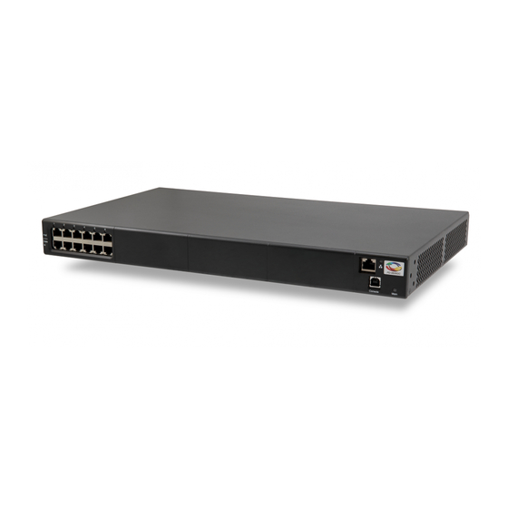
PD-96XXG PoE Multiport Series User Guide
Introduction
Microchip's family of Power over Ethernet (PoE) Midspans PD-96xxG series inject power over data-carrying Ethernet
cabling. Employing these devices reduces the need for AC outlets, local UPS, and AC/DC adapters near Powered
Devices (PDs).
PD-9606G/9612G Midspans support 6 and 12 ports in a 10/100/1000BaseTx Ethernet network respectively, over
TIA/EIA-568 category 5/5e/6 cabling. The PD-96xxG family series can provide up to 95W according to the HDBaseT
PoE standard. These PD-96xxG series implements a Twin High (TH) PSE system, delivering 47.5W over 2 pairs
(total 95W). DC power is supplied over both spare and data pairs of wires within a cable (1/2, 3/6, 4/5, and 7/8) to
terminal units.
PoE Midspan powers devices that are PoE enabled or equipped to receive PoE. These devices are called PDs.
PoE Midspans offer the following key features:
•
Safe and reliable power over an existing Ethernet infrastructure.
•
Remote management using web control and/or SNMPv3.
•
High-level of network security.
•
Safe solution that protects network infrastructure.
•
Standards compliant: PoH and IEEE
•
Provides safe Power and Data over a single RJ45 cable.
©
2021 Microchip Technology Inc.
and its subsidiaries
®
802.3at.
User Guide
PD-96XXG
DS00004055A-page 1
Advertisement
Table of Contents

Subscribe to Our Youtube Channel
Related Manuals for Microchip Technology PD-96G Series


Summary of Contents for Microchip Technology PD-96G Series
-
Page 1: Introduction
High-level of network security. • Safe solution that protects network infrastructure. ® • Standards compliant: PoH and IEEE 802.3at. • Provides safe Power and Data over a single RJ45 cable. User Guide DS00004055A-page 1 © 2021 Microchip Technology Inc. and its subsidiaries... -
Page 2: Table Of Contents
8.1. Power Backup..........................16 8.2. Power Redundancy........................16 8.3. Connectors..........................16 8.4. Connecting Backup and Redundancy Connectors..............17 8.5. Power Backup and Power Redundancy Indications..............19 Contacting Technical Support....................... 20 User Guide DS00004055A-page 2 © 2021 Microchip Technology Inc. and its subsidiaries... - Page 3 The Microchip Website..........................22 Product Change Notification Service......................22 Customer Support............................22 Microchip Devices Code Protection Feature....................22 Legal Notice..............................23 Trademarks..............................23 Quality Management System........................24 Worldwide Sales and Service........................25 User Guide DS00004055A-page 3 © 2021 Microchip Technology Inc. and its subsidiaries...
-
Page 4: Standards And Safety Guidelines
Read the following safety information before carrying out any installation, removal, or maintenance procedure on the PoE Midspan. Warnings contain directions to be followed for the safety of personal and product. User Guide DS00004055A-page 4 © 2021 Microchip Technology Inc. and its subsidiaries... - Page 5 Neutral and connected directly to the ground. U. K PoE Midspan is covered by General Approval NS/G/12345/J/100003, for indirect connection to a public telecommunications system. User Guide DS00004055A-page 5 © 2021 Microchip Technology Inc. and its subsidiaries...
-
Page 6: Information En Matière De Sécurité
RJ45 à ces prises. Le câblage Ethernet connexe doit être limité à l'intérieur de l'immeuble. • Le câblage Ethernet associé doit être limité à l'intérieur du bâtiment. User Guide DS00004055A-page 6 © 2021 Microchip Technology Inc. and its subsidiaries... -
Page 7: Data Input Ports
Power Indicator LED on the front panel displays power status of the PoE Midspan. When this LED is illuminated in green, it indicates that the Midspan is receiving AC power. For more information, see Table 3-1. 3.3.2 Port Indications The following sections detail PD-96xxG port indicators. User Guide DS00004055A-page 7 © 2021 Microchip Technology Inc. and its subsidiaries... - Page 8 Green blinks once every Valid load. Power is not connected to port. 0.5 seconds Total aggregated power exceeds No DC voltage is present on the port output predefined power budget. lines. User Guide DS00004055A-page 8 © 2021 Microchip Technology Inc. and its subsidiaries...
-
Page 9: Connectors
Each data port is configured as data “Pass-Through” ports for all data pins (pins 1, 2, 3, 6, 4, 5, 7, and 8). Use cabling of Category 5 or higher. User Guide DS00004055A-page 9 © 2021 Microchip Technology Inc. and its subsidiaries... -
Page 10: Poe Midspan Installation
Before proceeding, record the serial number of the unit in the following table for future reference. Serial number is found on the information label at the back of the PoE Midspan. Serial Number User Guide DS00004055A-page 10 © 2021 Microchip Technology Inc. and its subsidiaries... -
Page 11: Rack Mounting Brackets
Connect cables from PoH or IEEE 802.3at ready terminals (PDs) to corresponding Data and Power Out ports (upper row on front panel). Connecting Power Cables While using an AC source to power Midspan, plug-in the provided power cord to the AC connector. User Guide DS00004055A-page 11 © 2021 Microchip Technology Inc. and its subsidiaries... -
Page 12: Powering Up The Unit
– Power indicator remains lit in green while port indicators are OFF. Ports are now ready (enabled) for normal operation. If LEDs are not lit, see 5. Troubleshooting section for instructions. User Guide DS00004055A-page 12 © 2021 Microchip Technology Inc. and its subsidiaries... -
Page 13: Troubleshooting
Try to reconnect the same PD to a different port on the same Midspan or on another one. If it works, there is probably a faulty port or faulty RJ45 connection. User Guide DS00004055A-page 13 © 2021 Microchip Technology Inc. and its subsidiaries... -
Page 14: Specifications
DC Input Rated Voltage 53 V - 57 V Input DC Maximum Current 20 A Note: DC input from power backup Midspan only (not from external DC power supply source). User Guide DS00004055A-page 14 © 2021 Microchip Technology Inc. and its subsidiaries... -
Page 15: Microchip's Powerview Pro
Note: The PD-96xxG Midspan comes with the PowerView Pro software pre-installed. If the software needs to be re-installed or updated, the latest version is located at Microchip’s Software Library. User Guide DS00004055A-page 15 © 2021 Microchip Technology Inc. and its subsidiaries... -
Page 16: Power Backup And Power Redundancy Connection
Power Backup and Power Redundancy Control Signal Connector, COM D-Sub: 15 pins, 3 rows female connector. • DC Voltage Terminal Block Connector has two positive (+) terminals and two negative (-) terminals. User Guide DS00004055A-page 16 © 2021 Microchip Technology Inc. and its subsidiaries... -
Page 17: Connecting Backup And Redundancy Connectors
Verify Power Indicator LED is ON (Green LED). Note: While connecting a midspan to midspan - connect the earth ground cable between both units Earth Ground connection. Figure 8-2. Earth Ground Connection of PDs User Guide DS00004055A-page 17 © 2021 Microchip Technology Inc. and its subsidiaries... - Page 18 If Power Indicator LED is not lit, see 5. Troubleshooting section for instructions. Monitor Backup functionality through NMS, as shown in Figure 8-4. Consult Microchip for information on DC and COM cables. User Guide DS00004055A-page 18 © 2021 Microchip Technology Inc. and its subsidiaries...
-
Page 19: Power Backup And Power Redundancy Indications
Note: Midspan provides another power fail indication through Midspan's Power Indicator LED. Whenever unit's internal power supply fails, Power Indicator LED blinks once every second (Green LED). Figure 8-5. PD-96xxG Front Panel LED Indication User Guide DS00004055A-page 19 © 2021 Microchip Technology Inc. and its subsidiaries... -
Page 20: Contacting Technical Support
If you encounter any problems while installing or using this product, consult Microchip technical support team through the website or contact on the following number: USA/Canada Telephone: +1 877 480 2323 Internet: www.microchip.com/support User Guide DS00004055A-page 20 © 2021 Microchip Technology Inc. and its subsidiaries... -
Page 21: Revision History
PD-96XXG Revision History Revision History Revision Date Description 06/2021 Initial Revision User Guide DS00004055A-page 21 © 2021 Microchip Technology Inc. and its subsidiaries... -
Page 22: The Microchip Website
Attempts to break Microchip’s code protection feature may be a violation of the Digital Millennium Copyright Act. If such acts allow unauthorized access to your software or other copyrighted work, you may have a right to sue for relief under that Act. User Guide DS00004055A-page 22 © 2021 Microchip Technology Inc. and its subsidiaries... -
Page 23: Legal Notice
The Adaptec logo, Frequency on Demand, Silicon Storage Technology, and Symmcom are registered trademarks of Microchip Technology Inc. in other countries. GestIC is a registered trademark of Microchip Technology Germany II GmbH & Co. KG, a subsidiary of Microchip Technology Inc., in other countries. -
Page 24: Quality Management System
PD-96XXG Quality Management System For information regarding Microchip’s Quality Management Systems, please visit www.microchip.com/quality. User Guide DS00004055A-page 24 © 2021 Microchip Technology Inc. and its subsidiaries... -
Page 25: Worldwide Sales And Service
Tel: 631-435-6000 Sweden - Stockholm San Jose, CA Tel: 46-8-5090-4654 Tel: 408-735-9110 UK - Wokingham Tel: 408-436-4270 Tel: 44-118-921-5800 Canada - Toronto Fax: 44-118-921-5820 Tel: 905-695-1980 Fax: 905-695-2078 User Guide DS00004055A-page 25 © 2021 Microchip Technology Inc. and its subsidiaries...
Need help?
Do you have a question about the PD-96G Series and is the answer not in the manual?
Questions and answers