
Related Manuals for Cardinal CN20 Series


Summary of Contents for Cardinal CN20 Series
- Page 1 Cardinal ® CN20 Series Weight Indicating Instruments Technical Manual Cardinal Scale Mfg. Co. 8534-M514-O1 Rev B Printed in USA PO BOX 151 • WEBB CITY, MO 64870 5/98 417-673-4631 Fax: 417-673-5001...
-
Page 3: Table Of Contents
TABLE OF CONTENTS CN20 Digital Weight Indicating Instrument SPECIFICATIONS ........1 Congratulations on your purchase of a series INSTALLATION ..........1 CN20 Digital Weight Indicating Instrument. This Power Supply ........2 instrument, which has been designed and Batteries ..........2 manufactured in the U.S.A., incorporates the Load Cell Connection ......3 latest digital technology and includes features SETUP AND CALIBRATION ......3... -
Page 5: Specifications
SPECIFICATIONS Power Requirements: 12 VDC, 300ma Optional Power Supply Operating Temperature: 14°F (-10°C) to 104°F (40°C) Display: 4 ea. 0.7" 7-Segment High-Contrast LCD (CN20L) or: 0.56" 7-Segment Red LED (CN20E) Sensitivity: 1.5 uV/Graduation (0 - 3 mV/V input) Load Cell Excitation: 5.0 VDC Maximum Load Cell Cable Length: Capacities:... -
Page 6: Power Supply
INSTALLATION, Cont. Regardless of how you mount your CN20, it should be in a safe area where it will not be in the way of normal traffic. The mounting bracket should be securely fastened to the wall or column top so that it cannot break loose from the mounting surface. -
Page 7: Load Cell Connection
INSTALLATION, Cont. Alkaline batteries will last several months in an instrument with a LCD display. They will last only a couple of days in an instrument with a LED display. Therefore, it is recommended that rechargeable Ni-Cad batteries be used in instruments with LED displays. The battery charging circuitry is disabled. - Page 8 SETUP AND CALIBRATION, Cont. 2. If operating from batteries, verify that the batteries are new or Figure No. 5 Printed Circuit Board if Ni-Cad, that they are fully Calibration charged and that they have been Switch correctly installed in the battery drawer.
- Page 9 SETUP AND CALIBRATION, Cont. LOAD CALIBRATION WEIGHT The display will now indicate Lod= which is a prompt for the entry of the calibration weight value and placement of this amount of test weights on the scale platform. If the scale has been previously calibrated and you do not wish to change the calibration setting, simply press the HOLD/REL key twice without taking any other action and the internal calibration factor will be retained.
- Page 10 SETUP AND CALIBRATION, Cont. SAMPLE RATE, Cont. lb/kg keys until the desired sample rate is displayed then press the HOLD/REL key to save the setting. Note: Like the filtering level, the sample rate may be changed later without having to enter the calibration mode.
- Page 11 SETUP AND CALIBRATION, Cont. Figure No. 6 1. Press OFF key. 2. Press and hold calibration switch. 3. Press ON key. Filtering? FLt= 0, 1, 2 or 3 int= Interval 0=No Filtering 2=Moderate Filtering 1, 2 or 5 1=Minimal Filtering 3=Custom Filtering If 0, 1 or 2 then Decimal Point...
-
Page 12: Fine Span
This key is used to remove power from the CN20, turning it off. The CN20 series indicators can be equipped with a membrane keypad containing twenty (20) keys with full numeric keypad. This keypad is shown in detail in Figure No. 8. The following describes the... -
Page 13: Annunciators
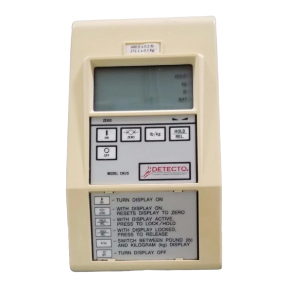
TEST KEY DETECTO MODEL CN20 This key is used to conduct a test of all A Division of Cardinal Scale Manufacturing Co. display and memory elements. The test consists of four (4) cycles each TEST lasting two (2) seconds: 1. -
Page 14: Setup Review
ANNUNCIATORS, Cont. STABLE The STABLE annunciator is identified with two small triangular shapes and is turned on when the weight display is stable. This means that the change in successive weight samples is less than the motion limits selected during setup and calibration of the CN20. The BAT annunciator is located to the right of the display and indicates that the battery voltage is low and the batteries will soon need to be recharged or replaced. -
Page 15: Battery Charging
BATTERY CHARGING, Cont. Figure No. 9 Install Jumper for Ni-Cad batteries. Remove Jumper for Alkaline Batteries Numeric Keypad Enabled International Application (causes the power up sequence to include memory and display test) PRINTED CIRCUIT BOARD JUMPER TABLE FACTORY SETUP CN20E CN20L PCB Side Shorted Function... -
Page 16: Care And Cleaning
ERROR AND STATUS DISPLAYS, Cont. Display Meaning -oF- Attempting to display a negative number greater than -999 or a positive number greater than 9,999. -oL- Scale weight exceeds scale capacity. CALb Indicates improperly stored calibration data; calibration is necessary. Indicates a disallowed keyboard entry: Attempt to zero when the weight is outside the scale zero range. -
Page 17: Replacement Part Id List
APPENDIX A REPLACEMENT PART IDENTIFICATION Figure no. 10 illustrates the various parts and assemblies that are available as replacement parts for the CN20. The chart following this figure lists part numbers and description of each item shown. When ordering a new printed circuit board assembly, make certain that you include the exact model number of your CN20 to ensure that you will receive the correct version of printed circuit board. - Page 18 NOTES...
Need help?
Do you have a question about the CN20 Series and is the answer not in the manual?
Questions and answers