
Related Manuals for Dometic Enerdrive EN43510


Summary of Contents for Dometic Enerdrive EN43510
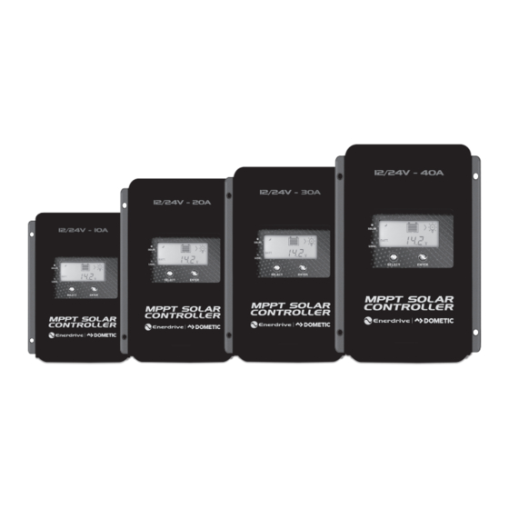
- Page 1 Owner’s Manual Rev: 1.0 (2021) EN43510 - MPPT Solar Controller 12/24V - 10Amp EN43520 - MPPT Solar Controller 12/24V - 20Amp EN43530 - MPPT Solar Controller 12/24V - 30Amp EN43540 - MPPT Solar Controller 12/24V - 40Amp...
- Page 2 MPPT Solar Controller Owners Manual Rev. 1.0. This Manual is applicable to all units with serial number pre x EN. Service Contact Information Dometic Power & Control (Enerdrive) Pty Ltd PO Box 9159, Wynnum Plaza, QLD 4178 Ph: 1300 851 535 / Fax: 07 3390 6911 Email: support@enerdrive.com.au | Web: www.enerdrive.com.au...
- Page 3 Exclusions For Documentation And Product Usage Unless speci cally agreed to in writing, Dometic Power & Control (Enerdrive) Pty Ltd: makes no warranty as to the accuracy, su ciency or suitability of any technical or other information provided in its manuals or other documentation.
-
Page 4: Table Of Contents
Table of Contents 1. GENERAL INFORMATION 1.1 OVERVIEW 1.2 CHARACTERISTICS 2. INSTALLATION 2.1 CAUTION 2.2 PV ARRAY REQUIREMENTS 2.3 WIRE SIZE 2.4 MOUNTING 3. DISPLAY 3.1 OVERVIEW 3.2 OPERATION 4. PARAMETERS SETTING 4.1 BATTERY PARAMETERS 4.1.1 SUPPORTED BATTERY TYPES 4.1.2 SETTINGS 4.2 LOAD WORKING MODES 5. -
Page 5: General Information
1. GENERAL INFORMATION 1.1 OVERVIEW The Enerdrive MPPT Solar Controllers adopt the advanced MPPT control algorithm, it can minimize the maximum power point loss rate and loss time, quickly track the maximum power point (MPP) of the PV array and obtain the maximum energy from solar array under any conditions; and it can increase the ratio of energy utilization in the solar system by 20%-30% compared with PWM charging method. -
Page 6: Characteristics
1.2 CHARACTERISTICS Figure 1 - Product Characteristics RTS* Port PV Terminals Battery Terminals Load Terminals RS485 Communication Port *If the temperature sensor is short circuited or damaged, the controller will charge discharge according to the voltage setting point at the default temperature setting of 25°C (no temperature condensation). -
Page 7: Installation
2. INSTALLATION 2.1 CAUTION • Please read the entire installation instructions to get familiar with the installation steps before installation. • Be very careful when installing the batteries, especially ooded lead-acid battery. Please wear eye protection and have fresh water available to wash and clean any contact with battery acid. •... -
Page 8: Pv Array Requirements
2.2 PV ARRAY REQUIREMENTS (1) MAXIMUM PV ARRAY POWER The MPPT controller has the function of charging current/power-limiting, that is, during the charging process, when the charging current or power exceeds the rated charging current or power, the controller will automatically limit the charging current or power to the rated range, which can e ectively protect the charging parts of controller, and prevent damages to the controller due to the connection of some over-speci cation PV modules. - Page 9 According to “Peak Sun Hours diagrams”, if the power of PV array exceeds the rated charging power of controller, then the charging time as per the rated power will be prolonged, so that more energy can be obtained for charging the battery. However, in the practical application, the maximum power of PV array shall be not greater than 1.5 x the rated charging power of controller.
-
Page 10: Wire Size
2.3 WIRE SIZE The wiring and installation methods must conform to all national and local electrical code requirements. PV WIRE SIZE Since PV array output can vary due to the PV module size, connection method or sunlight angle, the minimum wire size can be calculated by the Isc* of PV array. Please refer to the value of Isc in the PV module speci cation. - Page 11 BATTERY AND LOAD WIRE SIZE The battery and load wire size must conform to the rated current, the reference sizes as below are a guide only: LOAD RATED CHARGE RATED DISCHARGE BATTERY MODEL WIRE SIZE CURRENT CURRENT WIRE SIZE EN43510 4MM²/12AWG 4MM²/12AWG EN43520...
-
Page 12: Mounting
2.4 MOUNTING WARNING • Risk of explosion! Never install the controller in a sealed enclose with ooded batteries! Do not install in a con ned area where battery gas can accumulate. • Risk of electric shock! When wiring the solar modules, the PV array can produce a high open circuit voltage, so turn o the breaker before wiring and be careful when wiring. - Page 13 Step 2: Connect the system in the order of 1 battery > 2 load>3 PV array in accordance with Figure 2-2, ”Schematic Wiring Diagram” and disconnect the system in the reverse order 3>2>1. CAUTION • While wiring the controller do not close the circuit breaker or fuse and make sure that the leads of "+"...
- Page 14 Step 4: Connect Accessories • If the batteries being charged are in a di erent location to the solar controller it is recommended to use the remote temperature sensor. Controller Mounted Remote Temperature Sensor Temperature Sensor Connect the remote temperature sensor cable to the solar controller and place the other end close to the battery.
-
Page 15: Display
3. DISPLAY 2.1 CAUTION (1) LED Indicator INDICATOR COLOUR STATUS INSTRUCTION PV connection normal but low voltage (low output) Green On solid from PV, not charging Green No PV voltage (nighttime) or PV connection problem Slowly Charging Green Flashing (1Hz) Fast Green PV over voltage... - Page 16 (3) Interface INDICATOR ICON STATUS Night No Charging Array Charging PV Voltage, Current, Generated Energy Battery Capacity, In Charging Battery Battery Voltage, Current, Temperature Battery Type Load ON Load Load OFF Current/Consumed Energy/Load mode Page 16 MPPT Solar Controller Owners Manual Rev. 1.0.
-
Page 17: Operation
3.2. OPERATION (1) Browse Interface Press the button to cycle display the following interfaces. (2) Load Parameter Display Display: Current/Consumed energy/Load working mode-Timer1/ Load working mode-Timer2 (3) Setting Clear the generated energy Operation: Step 1: Press the button and hold 5s under the PV generated energy interface and the value will be ashing. - Page 18 Switch the battery temperature unit Press the button and and hold 5s under the battery temperature interface. Battery Type User Operation: Step 1: Press the button and hold 5s under the battery voltage interface. Step 2: Press the button when the battery type interface is ashing. Step 2: Press the button to con rm the battery type.
- Page 19 Load Working Mode Operation: Step 1: Press the button and hold 5s under the load mode interface. Step 2: Press the button when the load mode interface is ashing. Step 2: Press the button to con rm the load mode. NOTE: Please refer to chapter 4.2 for the load working modes.
-
Page 20: Parameters Setting
4. PARAMETERS SETTING 4.1 BATTERY PARAMETERS 4.1.1 SUPPORTED BATTERY TYPES Sealed (default) Battery Flooded Lithium Battery LiFePO4(4S/8S/15S/16S) User 4.1.2 SETTINGS WARNING When the default battery type is selected, the battery voltage parameters cannot be modi ed. To change these parameters, select the "USE" type. Step 1: Enter the “USE”... - Page 21 The SYS value can only be modi ed under the non-lithium "USE" type. That is, the battery type is Sealed, Gel, or Flooded before entering the "USE" type, the SYS value can be modi ed; if it is lithium battery type before entering the "USE" type, the SYS value cannot be modi ed.
-
Page 22: Load Working Modes
4.2 LOAD WORKING MODES 1) DISPLAY AND OPERATION When the LCD shows above interface, operate as following: Step 1: Press the button and hold 5s for the load mode interface. Step 2: Press the button when the load mode interface is ashing. Step 3: Press the button to con rm the load working modes. -
Page 23: Others
5. OTHERS 5.1 PROTECTION When the charging current or power of the PV array exceeds the controller’s rated current or power, it will be charge at the rated current or power. PV Over Current/Power WARNING: When the PV’s charging current is greater than the rated current, the PV’s open circuit voltage cannot greater than the "maximum PV open-circuit voltage", otherwise the controller may be damaged. - Page 24 When the battery voltage reaches the low voltage disconnect voltage, it will automatically stop battery discharging to prevent battery damage caused by over-discharging. (Any controller connected loads will be Battery Over Discharge disconnected. Loads directly connected to the battery will not be a ected and may continue to discharge the battery.) The controller can detect the battery temperature through an external temperature sensor.
-
Page 25: Troubleshooting
*When the internal temperature is 81 °C the reduce charging power mode which reduce the charging power of 5%,10%, 20%,40% every increase 1 °C is turned on. If the internal temperature is greater than 85 °C , the controller will stop charging. When the temperature declines to be below 75 °C , the controller will resume. - Page 26 Battery level shows When the battery voltage is restored to Battery empty, battery frame or above LVR (low voltage reconnect over Discharged and fault icon blink voltage), the load will recover. The controller will automatically turn Battery frame and Battery the system o .
-
Page 27: Maintenance
5.3 MAINTENANCE The following inspections and maintenance tasks are recommended at least two times per year for best performance. • Make sure controller rmly installed in a clean and dry ambient environment. • Make sure no block on air ow around the controller. Clear up any dirt and fragments on heat sink. •... -
Page 28: Technical Specifications
6. TECHNICAL SPECIFICATIONS Enerdrive Part No. EN43510 EN43520 EN43530 EN43540 Nominal Voltage Range 12/24VDC Auto Battery Voltage Range 8 ~ 32V Maximum Battery Current Load Current Rating 100V Maximum PV open circuit voltage (Battery Voltage +2V) ~ 72V MPPT Voltage Range 195W/12V 390W/12V 580W/12V... -
Page 29: Appendix | Conversion Efficiency Curves
Appendix I Conversion E ciency Curves Illumination Intensity: 1000W/m2 Temp: 25ºC Model: EN43510 1. Solar Module MPP Voltage(17V, 34V) / Nominal System Voltage(12V) 2. Solar Module MPP Voltage(34V,51V,68V) / Nominal System Voltage(24V) www.enerdrive.com.au Page 29... - Page 30 Model: EN43520 1. Solar Module MPP Voltage(17V, 34V) / Nominal System Voltage(12V) 2. Solar Module MPP Voltage(34V,51V,68V) / Nominal System Voltage(24V) Page 30 MPPT Solar Controller Owners Manual Rev. 1.0.
- Page 31 Model: EN43530 Solar Module MPP Voltage(17V, 34V) / Nominal System Voltage(12V) 1. Solar Module MPP Voltage(34V,51V,68V) / Nominal System Voltage(24V) www.enerdrive.com.au Page 31...
- Page 32 Model: EN43540 1. Solar Module MPP Voltage(17V, 34V) / Nominal System Voltage(12V) 2. Solar Module MPP Voltage(34V, 51V,68V) / Nominal System Voltage(24V) Page 32 MPPT Solar Controller Owners Manual Rev. 1.0.
- Page 33 NOTES www.enerdrive.com.au Page 33...
- Page 34 Dometic Power & Control (Enerdrive) Pty Ltd P.O. Box 9159, Wynnum Plaza, Queensland, Australia 4178 Ph: 1300 851 535 / Fax: 07 3390 6911 Email: support@enerdrive.com.au Web: www.enerdrive.com.au...
Need help?
Do you have a question about the Enerdrive EN43510 and is the answer not in the manual?
Questions and answers