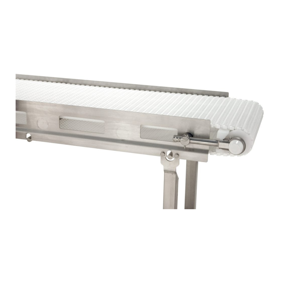
Dorner AquaPruf 7400 Series Installation, Maintenance, And Parts Manual
Curved nose bar
Hide thumbs
Also See for AquaPruf 7400 Series:
- Installation manual (66 pages) ,
- Installation, maintenance, and parts manual (46 pages) ,
- Installation, maintenance, and parts manual (44 pages)
Table of Contents
Advertisement
Quick Links
7400 Series Curved Nose Bar
Installation, Maintenance and Parts Manual
DORNER MFG. CORP.
P.O. Box 20 • 975 Cottonwood Ave.
Hartland, WI 53029-0020 USA
851-594 Rev. D
Conveyors
For other service manuals visit our website at:
www.dorner.com/service_manuals.asp
INSIDE THE USA
TEL: 1-800-397-8664
FAX: 1-800-369-2440
OUTSIDE THE USA
TEL: 262-367-7600
FAX: 262-367-5827
Advertisement
Table of Contents

Related Manuals for Dorner AquaPruf 7400 Series


Summary of Contents for Dorner AquaPruf 7400 Series
- Page 1 7400 Series Curved Nose Bar Conveyors Installation, Maintenance and Parts Manual DORNER MFG. CORP. INSIDE THE USA OUTSIDE THE USA P.O. Box 20 • 975 Cottonwood Ave. TEL: 1-800-397-8664 TEL: 262-367-7600 Hartland, WI 53029-0020 USA FAX: 1-800-369-2440 FAX: 262-367-5827 For other service manuals visit our website at: www.dorner.com/service_manuals.asp...
-
Page 2: Table Of Contents
The Dorner Limited Warranty applies. CAUTION Dorner 7400 Series conveyors have patents pending. Some illustrations may show guards Dorner reserves the right to make changes at any time removed. DO NOT operate equipment without without notice or obligation. guards. Dorner has convenient, pre-configured kits of Key Service Parts for all conveyor products. -
Page 3: Warnings - General Safety
Loose garments can become caught up in the conveyor. • Failure to comply could result in serious injury. SEVERE HAZARD! • Dorner cannot control the physical WARNING installation and application of conveyors. Taking protective measures is the responsibility of the user. -
Page 4: Specifications
• Non-accumulating product • Product moving toward gearmotor • Conveyor being mounted horizontally • Conveyor being located in a dry environment • Conveyor equipped with standard belt only 7400 Series Curved Nose Bar Conveyors Dorner Mfg. Corp. 851-594 Rev. D... -
Page 5: Conveyor Supports
Guide Profile Belt Material Drive Shaft Position Belt Material Guide Profile Stand Location Stand Holes Cleaning Options Cleaning Options Drive/ Pulley Type Length Length Belt Width Belt Width 7400 Series Curved Nose Bar Conveyors 851-594 Rev. D Dorner Mfg. Corp. -
Page 6: Installation
Installation Attach any guides / accessories. Refer to the "Service CAUTION Parts" section starting on page 30. Dorner recommends cleaning all the “food Conveyor Installation zones” prior to placing conveyor into service. Ensure adequate access is provided for cleaning and servicing equipment so that the Frame Section Connection required level of hygiene can be maintained. -
Page 7: Stand Installation
Attach the stands to the frame (Figure 10). Figure 7 Attach the flat connectors (Figure 8, item 1), if applicable, to the inside of the frame sections. Figure 10 Figure 8 7400 Series Curved Nose Bar Conveyors 851-594 Rev. D Dorner Mfg. Corp. -
Page 8: Tail Assembly Installation
Bolt the nose bar drive tail assembly to the conveyor frame (Figure 12). Figure 14 Figure 12 Install the drive package, if applicable. Refer to the “7400 Series Drive Package Installation, Maintenance and Parts Manual.” 7400 Series Curved Nose Bar Conveyors Dorner Mfg. Corp. 851-594 Rev. D... -
Page 9: Nose Bar Tip Up Tail
Key stops (x2) Figure 18 Attach nose bar idler shaft hands (Figure 19, item 1) to the tip up shaft (Figure 19, item 2). Figure 16 Figure 19 7400 Series Curved Nose Bar Conveyors 851-594 Rev. D Dorner Mfg. Corp. -
Page 10: Idler Tail
Figure 23 NOTE Do not insert the pull pins on the tension end of the conveyor until the belt has been installed. 7400 Series Curved Nose Bar Conveyors Dorner Mfg. Corp. 851-594 Rev. D... -
Page 11: Tip Up Tail
Figure 27 NOTE Do not insert the pull pins on the tension end of the conveyor until the belt has been installed. Figure 25 7400 Series Curved Nose Bar Conveyors 851-594 Rev. D Dorner Mfg. Corp. -
Page 12: Lifter Installation
(Figure 29, item 1). Make sure the hooked ends of the lifter bars are facing down when resting against the frame. Attach the lifter handle (Figure 29, item 3) to the belt lift pivot rod. 7400 Series Curved Nose Bar Conveyors Dorner Mfg. Corp. 851-594 Rev. D... -
Page 13: Curved Frame Sections
(Figure 35, item 2), of the frame. starting with the shortest wear strip on the inside of the curved section and working outward to the longest. Figure 33 Figure 35 7400 Series Curved Nose Bar Conveyors 851-594 Rev. D Dorner Mfg. Corp. -
Page 14: Belt Return Installation - Curved Frame Sections
Typical Belt Components (Figure 39) Chain belt Belt rod Figure 37 Attach the chain return shoes (Figure 37, item 1) to the curve return shafts (Figure 37, item 2). Figure 39 7400 Series Curved Nose Bar Conveyors Dorner Mfg. Corp. 851-594 Rev. D... - Page 15 Feed the ends of the belt through the top and bottom of the curved frame sections. Figure 44 Bring the ends of the belt together (Figure 42). Figure 42 7400 Series Curved Nose Bar Conveyors 851-594 Rev. D Dorner Mfg. Corp.
-
Page 16: Belt Return Installation - Straight Frame Sections
14 to remove slack from the belt. Figure 46 Up to 4" (102 mm) Figure 49 CAUTION Belt sag should not exceed 4" (102 mm) from the top of the returns. 7400 Series Curved Nose Bar Conveyors Dorner Mfg. Corp. 851-594 Rev. D... -
Page 17: Preventive Maintenance And Adjustment
LOCK OUT POWER before removing guards or performing maintenance. Exposed moving parts can cause serious injury. Dorner recommends cleaning the inside and the outside of the conveyor on a daily basis. Refer to the following steps to access the inside of the conveyor. -
Page 18: Periodic Cleaning
• Refer to “Wear Strip Installation” on page 12. • Refer to “Belt Return Installation – Straight Frame Sec- Periodic Cleaning tions” on page 16. Dorner recommends complete disassembly of the conveyor Maintaining the Conveyor Belt periodically for thorough cleaning. For conveyor disassembly and reassembly instructions: Troubleshooting •... -
Page 19: Conveyor Belt Replacement
Replacing a Section of Belt Remove the pull pins (Figure 57, item 1) on the tension end of the conveyor to release tension on the belt. Figure 55 Figure 57 7400 Series Curved Nose Bar Conveyors 851-594 Rev. D Dorner Mfg. Corp. -
Page 20: Replacing The Entire Belt
Replace the old section with a new section of belt. CAUTION DO NOT reuse belt rods that are damaged or Figure 61 show signs of wear. 7400 Series Curved Nose Bar Conveyors Dorner Mfg. Corp. 851-594 Rev. D... -
Page 21: Replacing The Entire Belt
(Figure 63, item 2) in the frame. Figure 64 Extend the idler tail to the next groove (Figure 64, item 2) on the bearing shaft. Figure 63 7400 Series Curved Nose Bar Conveyors 851-594 Rev. D Dorner Mfg. Corp. -
Page 22: Sprocket And Puck Removal
Remove the desired sprocket / puck by following these instructions: • A - Drive Sprocket Removal • B - Nose Bar Puck Removal • C - Idler Puck Removal Figure 67 7400 Series Curved Nose Bar Conveyors Dorner Mfg. Corp. 851-594 Rev. D... - Page 23 Loosen the 3 hole flange (Figure 69, item 1) with and flanged puck (Figure 71, item 2) off the drive bearing fasteners using a hex wrench spindle. (Figure 69, item 2). Figure 71 Figure 69 7400 Series Curved Nose Bar Conveyors 851-594 Rev. D Dorner Mfg. Corp.
-
Page 24: B - Nose Bar Puck Removal
(Figure 73, item 1) out of the nose bar drive weldment or idler hands (Figure 73, item 2). Figure 75 Figure 73 Remove the nose bar tracking pucks (Figure 73, item 3), if applicable. 7400 Series Curved Nose Bar Conveyors Dorner Mfg. Corp. 851-594 Rev. D... -
Page 25: Reassembling Tail Assemblies
Use a hex wrench (Figure 78, item 1) to loosen the bearing shaft assembly fasteners (Figure 78, item 2). Figure 80 Attach the nose bar wear strip (Figure 80, item 3). Figure 78 7400 Series Curved Nose Bar Conveyors 851-594 Rev. D Dorner Mfg. Corp. -
Page 26: Drive Tail Assembly
Attach the flanged pucks (Figure 82, item 1) and the 3 hole flange with bearing (Figure 82, item 2) to the drive spindle. Figure 84 Attach the nose bar wear strip (Figure 84, item 3). Figure 82 7400 Series Curved Nose Bar Conveyors Dorner Mfg. Corp. 851-594 Rev. D... -
Page 27: Idler Tail And Tip Up Tail
(Figure 86, item 2). Slide the idler puck onto the idler shaft (Figure 86, item 3). Make sure to center the idler puck. Figure 88 Attach the bearing covers. Figure 86 7400 Series Curved Nose Bar Conveyors 851-594 Rev. D Dorner Mfg. Corp. -
Page 28: Bearing Replacement
When inserting the new bearing, make sure the anti-rotation notch (Figure 90, item 1) on the bearing lines up with the groove inside the housing (Figure 90, item 2). 7400 Series Curved Nose Bar Conveyors Dorner Mfg. Corp. 851-594 Rev. D... - Page 29 NOTES NOTES 7400 Series Curved Nose Bar Conveyors 851-594 Rev. D Dorner Mfg. Corp.
-
Page 30: Service Parts
Service Parts Service Parts NOTE For replacement parts other than those shown in this section, contact an authorized Dorner Service Center or the factory. Key Service Parts and Kits are identified by the Performance Parts Kits logo . Dorner recommends keeping these parts on hand. - Page 31 1.00" Pitch Belt (Includes Items 1 through 5, 8, 9, 13 and 15) 74NBDC25-WW Nose Bar Drive Spindle Kit without a Dorner Gearmotor Mounting Package for Standard 1.00" Pitch Belt (Includes Items 1 through 5, 8, 9, 13 and 15)
-
Page 32: Nose Bar Tension End
6 and 9) 500487 Nose Bar Idler Shaft Left Hand WW = Conveyor width ref: 08 - 36 in 02 increments 500488 Nose Bar Idler Shaft Right Hand 7400 Series Curved Nose Bar Conveyors Dorner Mfg. Corp. 851-594 Rev. D... -
Page 33: Nose Bar Tip Up Tension End
Nose Bar Idler Shaft Left Hand through 6 and 9) 500488 Nose Bar Idler Shaft Right Hand WW = Conveyor width ref: 08 - 36 in 02 increments 500675 Key Stop 7400 Series Curved Nose Bar Conveyors 851-594 Rev. D Dorner Mfg. Corp. -
Page 34: Tension End Components
Idler Tail Kit for Specialty Intralox 5073WW Bent Retaining Bar for Specialty Belt (Includes Items 1 through 8) Intralox Belt WW = Conveyor width ref: 08 - 36 in 02 increments 7400 Series Curved Nose Bar Conveyors Dorner Mfg. Corp. 851-594 Rev. D... -
Page 35: Tip Up Tension End
Bent Retaining Bar for Specialty WW = Conveyor width ref: 08 - 36 in 02 increments Intralox Belt 5009WW Guard Bar 500675 Key Stop 5005WW Tip Up Shaft Assembly 807-1469 Pull Pin 7400 Series Curved Nose Bar Conveyors 851-594 Rev. D Dorner Mfg. Corp. -
Page 36: Curve Conveyor Frame And Wear Strips
Service Parts Curve Conveyor Frame and Wear Strips 7400 Series Curved Nose Bar Conveyors Dorner Mfg. Corp. 851-594 Rev. D... - Page 37 Example: Length = 95.25” LLLLL = 09525 90 & 90 90 & 90 45, 45, 45 & 45 WW = Conveyor width ref: 08 - 36 in 02 increments 7400 Series Curved Nose Bar Conveyors 851-594 Rev. D Dorner Mfg. Corp.
-
Page 38: Straight Conveyor Frame And Wear Strips
Conveyor Length (LLL) Number 020- 133- 253- 373- 493- 613- 733- 853- 501800-LLL Straight Wear Strip (Refer to chart) LLL = Conveyor length ref: 020 - 999 in 001 increments 7400 Series Curved Nose Bar Conveyors Dorner Mfg. Corp. 851-594 Rev. D... -
Page 39: Conveyor Frame Connection
500193 Hex Post Connector 961012MSS Hex Head Cap Screw M10- 1.5x12mm 961016MSS Hex Head Cap Screw M10- 1.5x16mm 500199 Flat Connector (Not Applicable if Stand Located at Connection) 7400 Series Curved Nose Bar Conveyors 851-594 Rev. D Dorner Mfg. Corp. -
Page 40: 3" (76 Mm) High Sides
503501-LLLLL Right Hand High Side Guide LLLLL = Guide Length in inches with 2 decimal places. 503601-LLLLL Left Hand High Side Guide Example: Guide Length = 95.25" LLLLL = 09525 807-1553 Pull Pin 7400 Series Curved Nose Bar Conveyors Dorner Mfg. Corp. 851-594 Rev. D... -
Page 41: Straight Belt Return
Curve Belt Return Item Part Number Description Item Part Number Description 500075 Chain Return Shoe 5033WW Curve Return Shaft WW = Conveyor width ref: 08 - 36 in 02 increments 7400 Series Curved Nose Bar Conveyors 851-594 Rev. D Dorner Mfg. Corp. -
Page 42: Curve Belt Chain Kit
Determine the length of chain required for the conveyor and round up to the nearest foot length. Order the proper number of chain repair kits (1' long each) for your conveyor. Dorner will ship chain kits that are of a reasonable length fully assembled. -
Page 43: Configuring A Conveyor Part Number
Curve Module Example: 744240901Z1MR4 Refer to your serial and model number plate (Figure 91). From the model number, determine conveyor width ( Curve module, 24" wide, 90°, ready for Dorner support length ( ), pulley type ( ), stand location, cleaning stands, including frame cutouts and MR belt material. -
Page 44: Return Policy
A representative will discuss action to be taken on the returned items and provide a Returned Goods Authorization number for reference. There will be a return charge on all new undamaged items returned for credit where Dorner was not at fault. Dorner is not responsible for return freight on such items.
Need help?
Do you have a question about the AquaPruf 7400 Series and is the answer not in the manual?
Questions and answers