Table of Contents
Advertisement
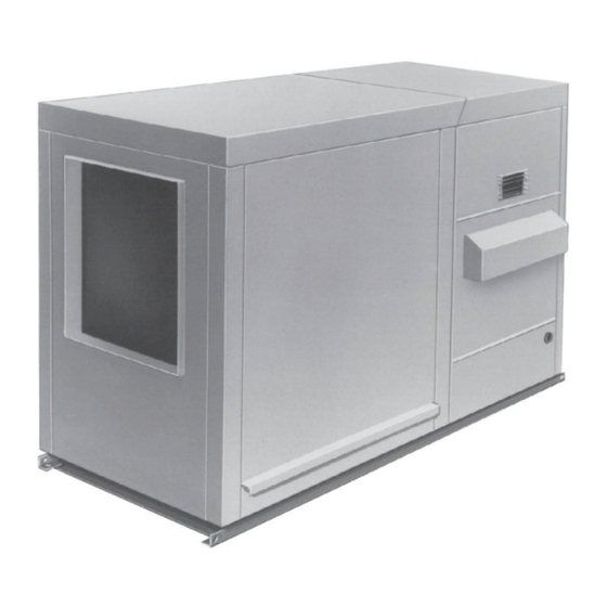
OUTDOOR PACKAGED DUCT FURNACE AND BLOWER
INSTALLATION, OPERATION, AND MAINTENANCE
• Failure to follow safety warnings exactly could result in serious injury, death, or property
damage.
• Improper installation, adjustment, alteration, service, or maintenance can cause serious injury,
death, or property damage.
• Installation and service must be performed by a qualified installer, service agency, or the gas
supplier.
• Be sure to read and understand the installation, operation, and service instructions in this
manual.
• Do not store or use gasoline or other flammable vapors and liquids in the vicinity of this or
any other appliance.
• Do not try to light any appliance.
• Do not touch any electrical switch; do not use any phone in your building.
• Leave the building immediately.
• Immediately call your gas supplier from a phone remote from the building. Follow the gas
supplier's instructions.
• If you cannot reach your gas supplier, call the fire department.
DO NOT DESTROY. PLEASE READ CAREFULLY. KEEP IN A SAFE PLACE FOR FUTURE REFERENCE.
MODEL RPB
⚠ DANGER ⚠
FIRE OR EXPLOSION HAZARD
WHAT TO DO IF YOU SMELL GAS
Revision: RPB-IOM (06-22) 131782-B
Supersedes: I-RPB (04-21) 131782-A
Advertisement
Table of Contents

Related Manuals for Reznor RPB


Summary of Contents for Reznor RPB
- Page 1 Revision: RPB-IOM (06-22) 131782-B Supersedes: I-RPB (04-21) 131782-A OUTDOOR PACKAGED DUCT FURNACE AND BLOWER INSTALLATION, OPERATION, AND MAINTENANCE MODEL RPB ⚠ DANGER ⚠ FIRE OR EXPLOSION HAZARD • Failure to follow safety warnings exactly could result in serious injury, death, or property damage.
-
Page 2: Table Of Contents
Computer-Controlled Electronic Modulation Between 50% and 100% Firing Rate (Option AG21) Electronic Modulation Between 20–28% and 100% Firing Rate (Option AG39) Electronic Modulation Between 20–28% and 100% Firing Rate (Option AG40) Pilot and Ignition Systems Burners and Carryover System Dampers and Damper Controls RPB-IOM (06-22) 131782-B... -
Page 3: General Information
OPT-AG7,8,9,9H 262319 100% outside air hood installation RPB-RPBL-RPDBL-AS2 132901 30% screened air hood installation OPT-AIR-HOOD 131794 Evaporative cooling module installation OPT-AS3,4,5,8 160202 Ignition controller replacement kit installation OPT-IGN-CNTRL 134704 Gas conversion OPT-GC 143147 Also available at www.reznorhvac.com. RPB-IOM (06-22) 131782-B... -
Page 4: Important Safety Information
If you do not have knowledge of local requirements, check with the local gas company or any other local agencies who might have requirements concerning this installation. • The instructions in this manual apply only to the model RPB packaged duct furnace and blower. Warranty Refer to the limited warranty information on the warranty card in the owner’s envelope. -
Page 5: Installation Codes
Height from top of cabinet to bottom of cabinet side. • The two-position discharge dampers in option AQ8 fit in the discharge air opening. The damper motor fits inside the downturn plenum cabinet. Figure 1. Dimensions (Refer to Table RPB-IOM (06-22) 131782-B... -
Page 6: Weights
• The location must comply with the clearances listed in Table • If the unit is equipped with an outside air hood, it is recommended that the inlet to the hood not be facing into the prevailing wind. RPB-IOM (06-22) 131782-B... -
Page 7: Hazards Of Chlorine
• This furnace was test-operated and inspected at the factory prior to crating and was in operating condition. If the furnace has incurred any damage in shipment, document the damage with the transporting agency and immediately contact an authorized Reznor ®... -
Page 8: Mounting Support Structure
The measurement from the duct openings to inside edge of roof curb is 1-5/8 inches (41 mm). Duct openings should be 1 inch larger than the duct size for installation clearance. RPB-IOM (06-22) 131782-B... -
Page 9: Optional Curb (Option Cj1 Or Cj2) Assembly
NOTE: The system can have a variety of configurations that affect installation. Figure 3 shows a unit with an option AQ5 or AQ8 downturn plenum, which is factory-installed as part of the packaged system. If the system does not have a downturn plenum, the discharge is horizontal. RPB-IOM (06-22) 131782-B... - Page 10 50-5/8 (1286) 56-1/8 (1426) 99-5/32 (2519) 104-21/32 (2658) 110-5/32 (2798) 118-7/16 (3008) 123-15/16 (3148) 129-7/16 (3288) Option CJ2 is for units with a factory-installed downturn plenum (option AQ5 or AQ8). Roof opening dimensions. Inside dimension of curb cap. RPB-IOM (06-22) 131782-B...
-
Page 11: Field-Supplied Support Structure
With downturn plenum (option AQ5 or AQ8). Although dimensions are included for units with a downturn plenum cabinet, it is strongly recommended that a full roof curb be used on an installation with a downturn plenum cabinet and/or a bottom return air duct. RPB-IOM (06-22) 131782-B... -
Page 12: Mounting
• Through unheated space: Insulate all exposed warm air ducts passing through an unheated space with 1-inch (not less than 1/2-inch) of insulation. • Duct supports: Suspend all ducts securely from adjacent buildings members. Do not support ducts from unit duct connections. RPB-IOM (06-22) 131782-B... - Page 13 • Return air duct/grill size: Ensure that return air ducting or grills have a free area equal to the size of the return duct connection. DETAIL A Figure 5. Connecting Ductwork to Furnace RPB-IOM (06-22) 131782-B...
-
Page 14: 100% Outside Air Hood (Option As2)
Refer to following formula for calculating sensor placement. This example assumes cross-sectional dimensions for supply ductwork of 24 × 12 inches (610 × 305 mm): RPB-IOM (06-22) 131782-B... - Page 15 (1) Determine where sensor wire should enter box and remove knockout. (2) Secure field-supplied cable connector to box, connect sensor wire, and install box cover. b. For all options, ensure that all sensor wires are connected in accordance with wiring diagram provided with unit. RPB-IOM (06-22) 131782-B...
-
Page 16: Piping Connections
• Test pressures above 1/2 psi—disconnect the heater and manual valve from the gas supply line to be tested. Cap or plug the supply line. • Test pressures below 1/2 psi—before testing, close the manual valve on the heater. RPB-IOM (06-22) 131782-B... -
Page 17: Gas Supply Piping
• After all connections are made, disconnect the pilot supply at the control valve and bleed the system of all air. Reconnect the pilot line and leak test all connections by brushing on a soap solution. • Gas connections sizes are listed in Table RPB-IOM (06-22) 131782-B... - Page 18 Table 10. Gas Connection Sizes Unit Size Gas Type 125–250 300–400 Connection Size (Inches (mm)) Natural gas 1/2 (13) 3/4 (19) Propane 1/2 (13) NOTE: The above are not supply line sizes. They are gas connection sizes for a standard unit. RPB-IOM (06-22) 131782-B...
-
Page 19: Electrical Connections
4 feet (1.2 meters) of service room between the switch and removable panels (see Figure 9). Refer to Table for field-supplied wiring sizes—from disconnect to electrical box—for connection to the motor contactor or starter. Figure 9. Disconnect Switch Locations RPB-IOM (06-22) 131782-B... -
Page 20: Control Wiring
17. Dirty Filter Pressure Switch 40. Air Proving switch 7. Main Low Gas Pressure Switch 28. Potentiometer 18. Line Voltage Connection 41. Venter Assembly 8. Pilot High Gas Pressure Switch 29. Filters 19. Convenience Outlet Figure 10. Control Locations RPB-IOM (06-22) 131782-B... - Page 21 Building pressure is set by turning adjustment screw. LOW actuation point is set by adjusting span of null by turning span adjustment screw. Span range is 0.01 to 0.03 IN WC. e. Refer to wiring diagram provided with unit to make electrical connections. RPB-IOM (06-22) 131782-B...
-
Page 22: Controls
Some thermostats are provided with this feature. Multiple units controlled from a single thermostat are shut off in the same manner. For proper operation, ensure that the blower fan control is wired correctly. RPB-IOM (06-22) 131782-B... -
Page 23: Limit Control
Both low fire and high fire stages are controlled by a Servo regulator that maintains constant gas input under wide variations in gas supply pressure. Refer to the instructions provided with the unit for gas valve specifications, wiring, and operating instructions. RPB-IOM (06-22) 131782-B... -
Page 24: Optional Two-Stage Control (Makeup Air Application)
3°F. Due to different cfm settings and outside air temperatures, the average downstream outlet temperature may not match the ductstat setting exactly. After the installation is complete, adjust the setpoint of the ductstat to achieve the desired average outlet air temperature. RPB-IOM (06-22) 131782-B... -
Page 25: Optional Ductstat With Electronic Remote Setpoint Module (Option Ag15)
(55–90°F) is identified as option AG8 or AG9. The temperature selector setting for option AG8 is on the amplifier Figure 13). Option AG9 has a remote temperature selector. Both systems are available with an override (see thermostat. AMPLIFIER SIGNAL CONDITIONER Figure 13. Maxitrol Amplifier and Signal Conditioner RPB-IOM (06-22) 131782-B... -
Page 26: Computer-Controlled Electronic Modulation Between 50% And 100% Firing Rate (Option Ag21)
The pilot tubing connects to the pilot port on the single-stage gas valve. RPB-IOM (06-22) 131782-B... -
Page 27: Electronic Modulation Between 20-28% And 100% Firing Rate (Option Ag40)
AG40 pressure requirements and to for troubleshooting option AG40. • This uniquely-designed modulation system requires combustion air pressure settings different from the standard Table 14 system. Refer to for the approximate combustion air proving switch settings at sea-level operation. RPB-IOM (06-22) 131782-B... - Page 28 Terminal 84 and switch. switch. Terminal 7? Terminal 2? Replace the Replace ignition primary manifold permissive pressure switch. relay. Figure 15. Troubleshooting Guide for Checking Bypass Combustion Air Damper Safety Circuit on Units with Option AG39 or AG40 RPB-IOM (06-22) 131782-B...
-
Page 29: Pilot And Ignition Systems
AG40) are equipped with two flash carryovers. Propane gas burners are equipped with one flash carryover and a regulated gas lighter tube system. • During regular service, check the main burner ports, the carryover assemblies, and the orifices for cleanliness. RPB-IOM (06-22) 131782-B... -
Page 30: Dampers And Damper Controls
The dirty filter switch is located in the furnace section. To adjust the dirty filter switch, refer to the Dirty Filter Switch Adjustment section. RPB-IOM (06-22) 131782-B... -
Page 31: Operation
On unit equipped with controller with lockout, if pilot is not established within 120 seconds switch closes main valve and (approximately), unit locks out for 1 hour unless reset by interrupting power to control circuit recycles spark gap RPB-IOM (06-22) 131782-B... -
Page 32: Post-Startup Checklist
Ensure that belt is aligned in pulley grooves properly and is not angled from pulley to pulley. b. Loosen adjusting screw locknut on motor base and turn adjusting screw until belt can be depressed 3/4 inches (19 mm). c. When correct belt tension is achieved, retighten adjusting screw locknut. RPB-IOM (06-22) 131782-B... -
Page 33: Adjusting Blower Speed
Table 17, which lists the Full Load Amps (FLA) of blower motors (open) based on Horsepower (HP) and Voltage (V), can be used for sizing line wiring but should not be interpreted as the exact motor amps. RPB-IOM (06-22) 131782-B... -
Page 34: Pressure Null Switch Adjustment
2. Remove electrical box cover and, while observing contacts, turn span adjustment screw slowly in clockwise direction. 3. Continue turning adjustment screw until you are able to see gaps between common and both low and high contacts—minimum gap provides greatest sensitivity—wider gap provides lower sensitivity. Figure 19. Pressure Null Switch Adjustment RPB-IOM (06-22) 131782-B... -
Page 35: Measure And Adjust Manifold (Outlet) Gas Pressure
3. Normally, adjustments to the factory-preset regulator should not be necessary. If adjustment is necessary, set pressure to correct settings by turning the regulator screw IN (clockwise) to increase pressure or OUT (counterclockwise) to decrease pressure. Consult the valve manufacturer’s literature provided with the furnace for more detailed information. RPB-IOM (06-22) 131782-B... -
Page 36: High Elevation (>2,000 Feet/609 Meters) Installations
If LP (propane) conversion is required, convert the unit in accordance with form OPT-GC listed in Table 1. When conversion is complete, verify that the input rate is correct. RPB-IOM (06-22) 131782-B... -
Page 37: Dirty Filter Switch Adjustment
WHILE UNIT IS OPERATING NEGATIVE PRESSURE CONNECTION ON FRONT OR TOP OF SWITCH SENSES BLOWER SIDE OF FILTERS POSITIVE PRESSURE CONNECTION ON BACK OR BOTTOM OF SWITCH SENSES AIR INLET SIDE OF FILTERS Figure 20. Dirty Filter Switch RPB-IOM (06-22) 131782-B... -
Page 38: Burner Air Shutter Adjustment
1. Loosen setscrew on return air damper rod at damper arm. 2. Manually open return air dampers. While dampers are opening, damper rod and arm will automatically move to their correct positions. 3. Tighten setscrew. Figure 21. Damper Linkage RPB-IOM (06-22) 131782-B... -
Page 39: Maintenance
1. Locate 1/8-inch FPT INLET pressure tap on combination gas valve (see NOTE: A manometer (fluid-filled gauge) with an inches water column scale is recommended. 2. With field-installed manual valve closed to prevent flow to gas valve, connect manometer to 1/8-inch FPT INLET Figure 22). pressure tap (see RPB-IOM (06-22) 131782-B... -
Page 40: Burner Rack Maintenance
For propane gas burner rack: (1) Break lighter tube connection at regulator and remove lighter tube orifice supply tubing. (2) Remove retaining screws in drip shield and remove shield. (3) Remove retaining screws and slide out lighter tube. RPB-IOM (06-22) 131782-B... -
Page 41: Cleaning Pilot And Burners
7. Use an air nozzle to blow out scale and dust accumulation from the burner ports. Alternate blowing compressed air through the burner ports and then through the venturi. Use a fine wire to dislodge any stubborn particles from the burner ports. 8. Clean the burner rack carryover systems using compressed air. RPB-IOM (06-22) 131782-B... -
Page 42: Spark Ignition System Maintenance
3. If the above conditions are normal and main gas flow is still off, the ignition controller is probably defective. Do not attempt to service the ignition controller as it does not contain any replaceable components. RPB-IOM (06-22) 131782-B... -
Page 43: Heat Exchanger Cleaning
Reinstall airflow baffles removed in step 1b and secure using baffle screws. e. Secure ductwork as necessary. TOP BAFFLE AIRFLOW BAFFLES SUPPORT SCREWS BAFFLE SCREWS TOP BAFFLE SUPPORT BOTTOM BAFFLE SUPPORT BRACKET SCREWS Figure 25. Airflow Baffles RPB-IOM (06-22) 131782-B... - Page 44 Clean V-tubes and reassemble heat exchanger. Burner Rack Maintenance e. Install burner rack assembly in accordance with section. 3. Check furnace for proper operation. Figure 26. Heat Exchanger V-Baffles Removal RPB-IOM (06-22) 131782-B...
-
Page 45: Troubleshooting
Faulty ignition controller If all checks listed in Spark Ignition System Maintenance section indicate no other cause, replace ignition controller (do not attempt to repair ignition controller, which has no field-replaceable parts) f. Poor microamp signal Adjust pilot regulator RPB-IOM (06-22) 131782-B... - Page 46 1. Improper motor pulley adjustment Ensure that motor pulley is properly-adjusted (refer to Adjusting Blower cuts out on Speed section) overload 2. Improper static pressure on duct system Adjust dampers in duct system 3. Low voltage Check power supply RPB-IOM (06-22) 131782-B...
- Page 47 NOTES RPB-IOM (06-22) 131782-B...
-
Page 48: Installation Record (To Be Completed By Installer)
For more information, contact your Factory Representative. Specifications and illustrations subject to change without notice or incurring obligations. Latest version of this manual is available at www.reznorhvac.com. ©2022 Nortek Global HVAC LLC, O’Fallon, MO. All rights reserved. RPB-IOM (06-22) 131782-B...
Need help?
Do you have a question about the RPB and is the answer not in the manual?
Questions and answers