Reznor RP Installation Operation & Maintenance
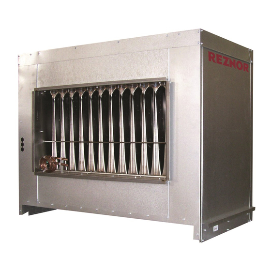
Outdoor duct furnace
Hide thumbs
Also See for RP:
- Installation operation & maintenance (32 pages) ,
- Installation, operation and maintenance manual (40 pages)
Table of Contents
Advertisement
®
!
WARNING:
FIRE OR EXPLOSION HAZARD
Failure to follow safety warnings exactly could result in serious injury, death, or
property damage.
Be sure to read and understand the installation, operation, and service instructions in
this manual.
Improper installation, adjustment, alteration, service, or maintenance can cause
serious injury, death, or property damage.
— Do not store or use gasoline or other flammable vapors and liquids in the vicinity
of this or any other appliance.
— WHAT TO DO IF YOU SMELL GAS
•
Do not try to light any appliance.
•
Do not touch any electrical switch; do not use any phone in your building.
•
Leave the building immediately.
•
Immediately call your gas supplier from a phone remote from the building. Follow
the gas supplier's instructions.
•
If you cannot reach your gas supplier, call the fire department.
— Installation and service must be performed by a qualified installer, service agency,
or the gas supplier.
Obsoletes Form I-OUTDOOR DUCT (Version D)
INSTALLATION / OPERATION / MAINTENANCE
Applies to: Model RP and Model HRPD
Model RP
Form I-RP/HRPD (Version E)
Outdoor Duct Furnaces
CQS
Form I-RP/HRPD, P/N 132210 R10, Page 1
Advertisement
Table of Contents
Troubleshooting

Related Manuals for Reznor RP


Summary of Contents for Reznor RP
- Page 1 Form I-RP/HRPD (Version E) ® Obsoletes Form I-OUTDOOR DUCT (Version D) INSTALLATION / OPERATION / MAINTENANCE Applies to: Model RP and Model HRPD Outdoor Duct Furnaces Model RP WARNING: FIRE OR EXPLOSION HAZARD Failure to follow safety warnings exactly could result in serious injury, death, or property damage.
-
Page 2: Table Of Contents
6.1 Gas Piping and Pressures ......7 APPENDIX ............. 26 6.2 Venting ............9 6.3 Duct Furnace Airflow ......10 Converting Model RP Duct Furnace for Lower Temperature Rise and Higher CFM Application ... 26 7.0 Electrical Supply and Connections ....12 7.1 General .............12 INDEX .............. -
Page 3: General Installation Information
Installation should be done by a qualified agency in accordance with the instructions in this manual and in compliance with all codes and requirements of authorities having Installation jurisdiction. The instructions in this manual apply to duct furnace Model RP and Model Information HRPD. -
Page 4: Uncrating And Preparation
3.2.2 Instructions for Model RP duct furnaces are equipped with directional air baffles between the heat exchanger tubes as shown in FIGURE 1. Facing the control compartment of the fur- Reversing Airflow by nace, the standard direction of airflow is from left to right. -
Page 5: Dimensions And Clearances
26 (660) 1/4” (6mm) 4-1/16 (103) diameter condensate Rear View Left Side View drain (2 per side) Model Series RP Dimensions - inches ± 1/8 / mm ±3 Gas Connection (inches) Natural Propane 30-15/16 28-1/2 15-1/4 20-5/16 786 648 387 1/2"... -
Page 6: Clearances
Size HRPD by Size Mounting Models RP, HRPD - These furnaces may be placed directly on a slab or roof where support is adequate. Support rails provide required clearance from combus- tibles. See mounting requirements in FIGURE 3. Form I-RP/HRPD, Page 6... -
Page 7: Mechanical
WARNING: All components of a gas supply system must be leak tested prior to placing equipment in service. NEVER TEST FOR LEAKS WITH AN OPEN FLAME. Failure to comply could result in personal injury, property damage or death. Form I-RP/HRPD, P/N 132210 R10, Page 7... -
Page 8: Gas Connection
FIGURE 4B - Gas Install the gas supply piping so that Connection Location when the union is disconnected, the - Model Series RP supply pipe will not interfere with and HRPD (Multiple Gas Supply the removal of the burner rack. (The... -
Page 9: Venting
Use venter seal plate as drill piping and template. supports 5” dia Flue Pipe 5” dia 90° Elbow 18” (457mm) Straight Pipe Oval Adapter Assy Combustion Air Intake Venter Seal Plate, P/N 43446 Oval Adapter Assy, PN/ 103025 Form I-RP/HRPD, P/N 132210 R10, Page 9... -
Page 10: Duct Furnace Airflow
The charts below show the approved temperature rise range with the required CFM and the internal pressure drop for each size of unit. Model RP (80% thermal efficient) Size Temp Rise CFM P.D. CFM P.D. CFM P.D. CFM P.D. CFM P.D. CFM P.D. CFM P.D. CFM P.D. CFM P.D. - Page 11 • Through Masonry Walls - No warm air duct should come in contact with masonry walls. Insulate around all air duct through masonry walls with not less than 1/2" (1" recommended) of insulation. Form I-RP/HRPD, P/N 132210 R10, Page 11...
-
Page 12: Electrical Supply And Connections
National Electric Code ANSI/NFPA No. 70 (latest edition) or, in Canada, the Canadian Electrical Code, Part I-C.S.A. Standard C22.1. In addition, the installer should be aware of and in compliance with any local ordinances or gas com- pany requirements that might apply. Form I-RP/HRPD, Page 12... -
Page 13: Supply Voltage And Wiring
(24V Transformer has 20VA capacity) Single-Stage Valve - .6 Two-Stage Valve - .6 Maxitrol System - .5 Spark Ignition System - .1 Fan Control Coil - .12 Time Delay Relay Heater - .1 Relay Coil - .12 Form I-RP/HRPD, P/N 132210 R10, Page 13... -
Page 14: Typical Wiring Diagrams
OPERATING SEQUENCE NOTE WIRING CODE - SET THERMOSTAT AT LOWEST SETTING. FACTORY WIRING - THE FOLLOWING CONTROLS ARE SUPPLIED BY REZNOR FOR FIELD INSTALLATION: BLACK - BK - TURN ON POWER AND MANUAL GAS VALVE TO UNIT. NONE BROWN - BR FIELD WIRING - SET THERMOSTAT AT DESIRED SETTING. -
Page 15: Controls
BLACK - BK BROWN - BR FIELD CONTROL WIRING NOTE RED - R TOTAL WIRE MINIMUM RECOMMENDED - THE FOLLOWING CONTROLS ARE SUPPLIED BY REZNOR FOR FIELD INSTALLATION: ORANGE - O LENGTH WIRE SIZE NONE YELLOW - Y 150 FEET #18 GA. -
Page 16: Limit Control
130°F. The remote modules are shipped separately for field installation. Follow the wiring diagram with the unit and the manufacturer's instructions for wiring and installation. Form I-RP/HRPD, Page 16... - Page 17 90°F) are identified as either Option AG8 or Option AG9. The temperature selector set- ting for Option AG8 is on the amplifier; Option AG9 has a remote temperature selector. Both systems are available with an override thermostat. Form I-RP/HRPD, P/N 132210 R10, Page 17...
- Page 18 100% Firing Rate, mal efficiency at full fire. Option AG39 - natural Model / Maximum MBH Inlet Inlet Pressure to Gas Supply Pressure gas Model RP only; not Size Turndown Range Modulating Valve Required available on Size 350 25-125 3.9" w.c.
-
Page 19: Troubleshooting
7 and Terminals 2 and 7. ignition premissive relay and Replace secondary Terminal 2? Replace secondary Terminal 7? manifold pressure manifold pressure switch. switch. Replace the primary manifold pressure switch. Replace ignition permissive relay. Form I-RP/HRPD, P/N 132210 R10, Page 19... -
Page 20: Pilot And Ignition Systems
Spark Gap 1/4”± 1/32” pilot assembly must be (6.38mm±.79) grounded to the heater for 7/64” (2.78mm) SIDE proper spark. VIEW OF Centerline of PILOT first burner 7/16”± 1/16” 23/32” VIEW (11mm±1.6) TOP VIEW OF BURNER (18.25mm) Form I-RP/HRPD, Page 20... -
Page 21: Burners And Carryover System
If either c) or d) above indicate a leak, locate leak by brushing a soapy solution on all fittings. Bubbles will appear at a leak. Repair and repeat tests. Check to make sure that flue discharge openings are free from obstructions. Form I-RP/HRPD, P/N 132210 R10, Page 21... -
Page 22: Startup
If the furnace is operating in an area where an unusual amount of dust or soot or other impurities are present in the air, more frequent inspec- tion is recommended. Form I-RP/HRPD, Page 22... -
Page 23: Maintenance Schedule
6. Uncouple the union in the gas supply. 7. Remove sheetmetal screws in the top corners of the burner rack assembly. 8. Pull "drawer-type" burner rack out of the furnace. To disassemble the burner rack: 1. Remove Carryover System -- Form I-RP/HRPD, P/N 132210 R10, Page 23... - Page 24 Clean the inner surfaces of the heat exchanger from beneath using the brush to "scrub" the tube walls to remove any accumulated dust, rust and/or soot. Clean the "V" tubes and re-assemble the heat exchanger and the furnace. Check the furnace for proper operation. Form I-RP/HRPD, Page 24...
-
Page 25: Troubleshooting
2. Replace fan control. During 3. Incorrect manifold pressure. 3. Check manifold line pressure (See Paragraph 6.1). Operation 4. Blower set for too low temperature rise. 4. Slow down blower or increase static pressure. Form I-RP/HRPD, P/N 132210 R10, Page 25... -
Page 26: Appendix
CFM. WARNING: The instructions in this sheet are designed to prepare a Reznor duct furnace for increased air throughput conversion prior to installation. If your duct furnace is installed, for your safety, turn off the gas and the electric before servicing. - Page 27 Step 1. Test for proper operation. Be sure to comply with the air throughputs in the table on page 26. Form I-RP/HRPD, P/N 132210 R10, Page 27...
-
Page 28: Index
_________________________________________________________________ For service or repair BUILDING OWNER • Contact the installer listed above. OR MAINTENANCE • If you need additional assistance, contact the Reznor Distributor listed above. ® PERSONNEL: • For more information, contact your Reznor Representative by calling ®...
Need help?
Do you have a question about the RP and is the answer not in the manual?
Questions and answers