Reznor RPB Manual
Packaged duct furnace and blower
Hide thumbs
Also See for RPB:
- Installation (4 pages) ,
- Installation, operation and maintenance manual (48 pages) ,
- Quick start manual (4 pages)
Table of Contents
Advertisement
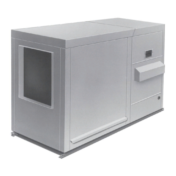
INSTALLATION/OPERATION/MAINTENANCE FOR OUTDOOR
PACKAGED DUCT FURNACE AND BLOWER
• Failure to follow safety warnings exactly could result in serious injury, death, or property damage.
• Improper installation, adjustment, alteration, service, or maintenance can cause serious injury,
death, or property damage.
• Installation and service must be performed by a qualified installer, service agency, or the gas
supplier.
• Do not store or use gasoline or other flammable vapors and liquids in the vicinity of this or any
other appliance.
• Do not try to light any appliance.
• Do not touch any electrical switch; do not use any phone in your building.
• Leave the building immediately.
• Immediately call your gas supplier from a neighbor's phone. Follow the gas supplier's instructions.
• If you cannot reach your gas supplier, call the fire department.
DO NOT DESTROY. PLEASE READ CAREFULLY. KEEP IN A SAFE PLACE FOR FUTURE REFERENCE.
MODEL RPB
⚠ DANGER ⚠
FIRE OR EXPLOSION HAZARD
WHAT TO DO IF YOU SMELL GAS
Revision: I-RPB (04-21) 131782-A
Supersedes: I-RPB (04-15) PN131782R13
Advertisement
Table of Contents

Related Manuals for Reznor RPB


Summary of Contents for Reznor RPB
- Page 1 Revision: I-RPB (04-21) 131782-A Supersedes: I-RPB (04-15) PN131782R13 INSTALLATION/OPERATION/MAINTENANCE FOR OUTDOOR PACKAGED DUCT FURNACE AND BLOWER MODEL RPB ⚠ DANGER ⚠ FIRE OR EXPLOSION HAZARD • Failure to follow safety warnings exactly could result in serious injury, death, or property damage.
-
Page 2: Table Of Contents
Read the installation, operation, and maintenance instructions thoroughly before installing or servicing this equipment. WARNING To ensure safety, follow lighting instructions located on the outlet box cover. Refer to Hazard Levels. I-RPB (04-21) 131782-A, Page 2... -
Page 3: General Installation Information
This furnace was test operated and inspected at the factory prior to crating and was in operating condition. If the furnace has incurred any damage in shipment, document the damage with the transporting agency and immediately contact an authorized Reznor ®... -
Page 4: Preparing The Furnace For Installation
3.1 Uncrating and Inspecting (cont'd) 3.0 Uncrating and Preparation distributor. If you are an authorized Distributor, follow the FOB freight policy procedures as published by Reznor for Reznor products. ® (cont'd) Check the rating plate for the gas specifications and electrical characteristics of the furnace to be sure that they are compatible with the gas and electric supplies at the installation site. -
Page 5: Clearances
(see FIGURE 3A). If the system includes an outside air hood, attach it after the unit is in place. I-RPB (04-21) 131782-A, Page 5... -
Page 6: Mounting Base And Methods
Except for the curb assembly details which are specific to the optional roof curb available with the system, the information and requirements I-RPB (04-21) 131782-A, Page 6... - Page 7 Roof Curb Dimensions (inches) Roof Curb Dimensions (mm) Size 150, 175 200, 225 250, 300 Size 125 150, 175 200, 225 250, 300 350 Option CJ1—Roof Curb for (H)RPB Option CJ1—Roof Curb for (H)RPB 60-5/8 60-5/8 60-5/8 60-5/8 60-5/8 60-5/8...
-
Page 8: Mechanical
All piping must be in accordance with requirements outlined in the National Fuel Gas Code NFPA54/ANSI Z223.1 (latest edition) or CSA-B149.1 (latest edition) Natural Gas and Propane Installation Code. Gas supply piping installation should conform with good practice and with local codes. I-RPB (04-21) 131782-A, Page 8... - Page 9 All components of a gas supply system must be leak tested prior to placing equipment in service. NEVER TEST FOR LEAKS WITH AN OPEN FLAME. Failure to comply could result in personal injury, property damage, or death. I-RPB (04-21) 131782-A, Page 9...
- Page 10 Consult the valve manufacturer's literature provided with the fur- nace for more detailed information. CAUTION: DO NOT bottom out the gas valve regulator adjusting screw. This can result in unregulated manifold pressure causing overfire and heat exchanger failure. I-RPB (04-21) 131782-A, Page 10...
- Page 11 11830 11833 11830 125, 175, 225, 300, 350, 400 11828 97360 1.35 mm 5001–6000 150,250 16590 39658 38678 39658 125, 175, 225, 300, 350, 400 11833 97360 1.35 mm 6001–7000 150,250 84853 39658 38678 39658 I-RPB (04-21) 131782-A, Page 11...
-
Page 12: High Elevation (>2,000 Feet/609 Meters) Installations
5” dia Flue Pipe 5” dia 90° Elbow 18” (457mm) Straight Pipe Oval Adapter Assy Venter Seal Plate, Combustion Air Intake P/N 43446 Oval Adapter Assy, PN/ 103025 I-RPB (04-21) 131782-A, Page 12... -
Page 13: Unit Inlet Air
150,175 34-1/8 31-11/32” (796mm) 200,225 39-5/8 1006 250,300 47-7/8 1216 53-3/8 1356 58-7/8 1495 NOTE: The width of the outside air hood 14” (356mm) is the same as the width of the blower minimum cabinet. I-RPB (04-21) 131782-A, Page 13... - Page 14 The air hood flange must be Opening Options between the blower cabinet top and the cabinet end panel. Vertical Slots - 30% Outside 3. Reinsert all of the sheet metal Slide side flanges Opening Air Hood screws. into these slots. I-RPB (04-21) 131782-A, Page 14...
- Page 15 4500 0.09 0.18 0.18 (1) 16x20; 5000 0.12 0.22 0.22 (1) 16x25; 5500 0.14 0.27 0.27 (2) 20x20; 6000 0.17 0.32 0.32 (2) 20x25 6500 0.20 0.38 0.37 7000 0.23 0.44 0.43 7400 0.49 0.48 I-RPB (04-21) 131782-A, Page 15...
- Page 16 4. Adjustment of the Switch: The HIGH actuation point of the null switch is indi- cated on a calibrated scale secured to the transparent range screw enclosure. I-RPB (04-21) 131782-A, Page 16...
- Page 17 Use a field-supplied 1/4" diameter tubing with a compression nut and tubing ferrule to connect the fresh water supply to the inlet of the float valve (see FIGURE 15). Place nut and ferrule over tubing and insert tubing into the float valve stem. Tighten nut securely. I-RPB (04-21) 131782-A, Page 17...
- Page 18 Follow the manufacturer's instructions to install and maintain the water hammer arrestor. A freeze protection kit (option CT5) is also available. I-RPB (04-21) 131782-A, Page 18...
- Page 19 (see FIGURE 19A) consistently along the entire pipe length, 2) the media pads wet evenly after a few ON cycles (no dry spots or dry streaks), and 3) a slight amount of excess water collects at the drain at the completion of the ON cycle. I-RPB (04-21) 131782-A, Page 19...
- Page 20 (1) 106034 (1) 106035 Select the correct replacement part numbers and order replacement media pads from your distributor. Follow the instructions that follow and remove and replace pads as shown in FIGURES 20 and 21. I-RPB (04-21) 131782-A, Page 20...
- Page 21 Using a mild soap solution, wash all deposits from the inside of the pump and remove all debris from the impeller. 6. Reassemble the pump. Replace the parts in exact reverse order, being careful that everything is returned to its proper position. I-RPB (04-21) 131782-A, Page 21...
-
Page 22: Supply Air Discharge
Through Unheated Space: Insulate all exposed warm air ducts passing through an unheated space with at least 1/2" (1" is recommended) of insulation. • Duct Supports: Suspend all ducts securely from adjacent buildings members. Do not support ducts from unit duct connections. I-RPB (04-21) 131782-A, Page 22... - Page 23 FIGURE 23A. Options AG8, AG9, and AG39 include a sensor and mixing tube like the one shown in FIGURE 23B. Option AG40 requires a field-supplied sensor. Follow the instructions below to install the sensor in the ductwork. For control information, refer to Paragraph 8.1. I-RPB (04-21) 131782-A, Page 23...
-
Page 24: Blowers, Belts, And Drives
If the duct resistance is low, the blower may deliver too high an air volume. If the resis- tance is very low, the blower may deliver excess air to overload the motor, causing the I-RPB (04-21) 131782-A, Page 24... - Page 25 1800 is synchronous speed; assume 2% slip. Motor will run between 1750 and 1790 RPM at full load depending on design. Run the same motor at 45Hz (120 × 45/4 = 1350). 1350 RPM less 2% slip equals about 1300 RPM. I-RPB (04-21) 131782-A, Page 25...
-
Page 26: Electrical Supply And Connections
All wiring to the convenience outlet must meet local, state and national codes and regulations with the National Electrical Code ANSI/NFPA No. 70 (latest edi- tion) or in Canada, the Canadian Electric Code Part 1 CSA C.22.1. I-RPB (04-21) 131782-A, Page 26... -
Page 27: Wiring Diagrams
Maxitrol temperature selector. Consoles are shipped separately for remote installation and may be either mounted on a wall or recessed. I-RPB (04-21) 131782-A, Page 27... -
Page 28: Electrical Operating Components
In case of belt breakage or motor failure, the limit control will be opened by the high temperatures caused by reverse flow from the heat exchanger to the blower com- partment, thus breaking the circuit to the automatic electric gas valve and preventing burner operation. I-RPB (04-21) 131782-A, Page 28... -
Page 29: Controls
Servo regulator, maintaining constant gas input under wide variations in gas supply pressure. Refer to the instructions packed with the unit for specific gas valve specifications, wiring, and operating instructions. I-RPB (04-21) 131782-A, Page 29... - Page 30 When no DC current is fed to this device, it functions as a gas pressure regulator, supplying 3.5 IN WC pressure to the main operating valve. Refer to the wiring diagram supplied with the furnace for proper wiring connections. I-RPB (04-21) 131782-A, Page 30...
- Page 31 1.1 IN WC, the primary gas pressure switch in the manifold acti- vates the gear motor that controls the bypass damper in the venter/combustion air system. The bypass damper opens diverting some of the incoming air directly into the I-RPB (04-21) 131782-A, Page 31...
- Page 32 Is there 24 volts Go to between Terminal 2 on #1 wiring connections are secure. Troubleshooting Time Delay Relay and Model RPB with Option AG39 Chart for heater. Terminal 7? or Option AG40 Check combustion Is the Is there voltage...
-
Page 33: Pilot And Ignition Systems
7/64" Burner Rack Pilot Front Orifice Spark Electrode Spark Gap 1/4”± 1/32” (6.38mm±.79) 7/64” (2.78mm) SIDE VIEW OF Centerline of PILOT first burner 7/16”± 1/16” 23/32” VIEW (11mm±1.6) TOP VIEW OF BURNER (18.25mm) I-RPB (04-21) 131782-A, Page 33... -
Page 34: Burners And Carryover System
Observe gas meter for movement, or d) Attach pressure gauge readable to 0.1 IN WC and, after turning gas on for 10 seconds, turn gas supply OFF. No change in pressure should occur over a 3-minute period. I-RPB (04-21) 131782-A, Page 34... -
Page 35: Startup
Always comply with the combustion air requirements in the installation codes and instruc- tions. Combustion air at the burner should be regulated only by manufacturer-provided equipment. NEVER RESTRICT OR OTHERWISE ALTER THE SUPPLY OF COMBUSTION AIR TO ANY HEATER. I-RPB (04-21) 131782-A, Page 35... -
Page 36: Maintenance And Service
Observe the gas pressure. There should overfire and heat be no loss of gas pressure on the manometer. If the manometer indicates a loss of exchanger failure. pressure, replace the combination gas valve before placing the heater in operation. I-RPB (04-21) 131782-A, Page 36... - Page 37 Furnaces designed to provide high efficiency heating have V-shaped baffles in the top of each heat exchanger tube. Fol- low the instructions below to remove the V-baffles when cleaning the inner surfaces of the heat exchanger. I-RPB (04-21) 131782-A, Page 37...
-
Page 38: Troubleshooting
8. Optional lockout device interrupting control circuit by above causes Reset lockout by interrupting control at thermostat 9. Faulty combustion air proving switch Replace combustion air proving switch 10. Activated blocked vent switch (indoor system) Correct venting problem and reset switch I-RPB (04-21) 131782-A, Page 38... - Page 39 G. Motor 1. Improper motor pulley adjustment Check air throughput (refer to Paragraph 6.7) cuts out on 2. Improper static pressure on duct system Adjust dampers in duct system overload 3. Low voltage Check power supply I-RPB (04-21) 131782-A, Page 39...
-
Page 40: Installation Record (To Be Completed By Installer)
If you need additional assistance, contact the Distributor listed above. • For more information, contact your Factory Representative. Specifications and illustrations subject to change without notice or incurring obligations. ©2021 Nortek Global HVAC LLC, O’Fallon, MO. All rights reserved. I-RPB (04-21) 131782-A...
Need help?
Do you have a question about the RPB and is the answer not in the manual?
Questions and answers