Table of Contents
Advertisement
®
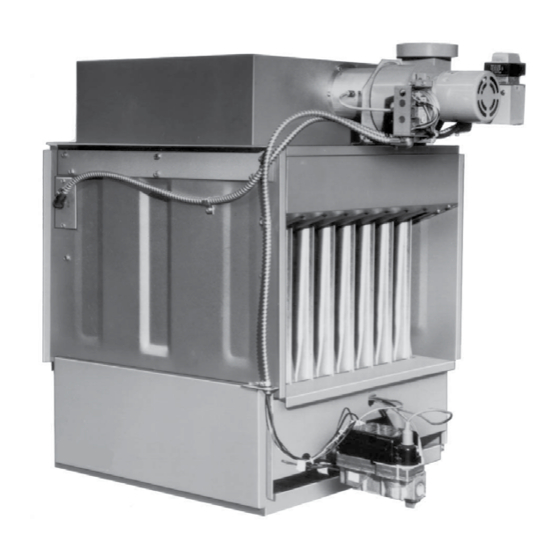
Model EEDU Duct Furnace
!
WARNING:
FIRE OR EXPLOSION HAZARD
Failure to follow safety warnings exactly could result in serious injury, death, or
property damage.
Be sure to read and understand the installation, operation, and service instructions in
this manual.
Improper installation, adjustment, alteration, service, or maintenance can cause
serious injury, death, or property damage.
— Do not store or use gasoline or other flammable vapors and liquids in the vicinity
of this or any other appliance.
— WHAT TO DO IF YOU SMELL GAS
•
Do not try to light any appliance.
•
Do not touch any electrical switch; do not use any phone in your building.
•
Leave the building immediately.
•
Immediately call your gas supplier from a phone remote from the building. Follow
the gas supplier's instructions.
•
If you cannot reach your gas supplier, call the fire department.
— Installation and service must be performed by a qualified installer, service agency,
or the gas supplier.
Installation / Operation / Maintenance
Applies to:
CQS
Form I-EEDU (Version B)
Obsoletes Form I-EEDU (Version A)
Model EEDU
Indoor,
Power-Vented
Duct Furnace
Form I-EEDU, P/N 150492 R4, Page 1
Advertisement
Table of Contents

Related Manuals for Reznor EEDU


Summary of Contents for Reznor EEDU
- Page 1 • If you cannot reach your gas supplier, call the fire department. — Installation and service must be performed by a qualified installer, service agency, or the gas supplier. Form I-EEDU, P/N 150492 R4, Page 1...
-
Page 2: Table Of Contents
Installation jurisdiction. Information The instructions in this manual apply only to the Reznor Model EEDU duct furnace. 1.3 Warranty Refer to the limited warranty form in the "Literature Bag". Warranty is void if.. -
Page 3: Installation Codes
2.2 Combustion Air A Model EEDU duct furnace is designed to take combustion air from the space in which the furnace is installed. The air that enters into the combustion process is vented to the Requirements outdoors. -
Page 4: Uncrating And Preparation
This furnace was test operated and inspected at the factory prior to crating and was in operating condition. If the furnace has incurred any damage in shipment, document the damage with the transporting agency and contact an authorized Reznor Distribu- tor. If you are an authorized Distributor, follow the FOB freight policy procedures as published by Thomas &... -
Page 5: Heat Exchanger
NOTE: It may be necessary to move cable connections. Re-insert screws to plug all holes in the side panel. After the limit control is installed, the cable connections may be re-attached using field-supplied sheetmetal screws. Form I-EEDU, P/N 150492 R4, Page 5... - Page 6 3 Furnaces - Option CR2 Filler (P/N 82654) Plates Item Description Item Description 4 Furnaces - Option CR3 Socket Assembly Spotweld Nut (P/N 82655) Bolt Tie Plate 5 Furnaces - Option CR4 (P/N 82656) Lockwasher Hanger Angles Form I-EEDU, Page 6...
-
Page 7: Dimensions And Clearances
860mm coupled units. 39-3/8" 1000mm (Discharge Duct) 44-7/8" 1140mm 4.0 Dimensions and Clearances 4.1 Dimensions FIGURE 5 - Model EEDU Dimensions - inches (mm) Electric Supply 16 (406) 5 (127) of Hangers of Hangers Limit Control 6-3/4 FRONT VIEW SIDE VIEW... -
Page 8: Suspending Or Mounting The Furnace
Keep area clean and maintain 29” (737mm) Air Inlet clearance for burner 6” (152mm) minimum rack service. clearance Re-locate hanger 12” (305mm) clearance bracket to this to combustibles required location when base from furnace bottom mounting heater. Form I-EEDU, Page 8... -
Page 9: Mechanical
75-250 300-400 Natural Gas 1/2" 3/4" Manual shutoff Propane 1/2" 1/2" To Gas Valve Ground NOTE: To permit burner removal, this nipple Drip Joint must extend beyond the edge of the heater. Union Form I-EEDU, P/N 150492 R4, Page 9... -
Page 10: Venting
(Horizontal vent run is recommended for maximum fuel savings.) If a vent cap is shipped with the heater, it is packaged attached to the venter housing. Detach the vent cap from the housing. Form I-EEDU, Page 10... - Page 11 A minimum of 12" (305mm) of straight pipe is required at the venter outlet (or transition fitting) before installing an elbow in the vent system. An elbow should never be attached directly to the venter. Form I-EEDU, P/N 150492 R4, Page 11...
- Page 12 Vent Length Table 1 is used; install the vent cap provided. If a vent cap is not included or if a non-standard size (Vent Length Table 2) of vent pipe is used, provide a Reznor Option CC1 vent cap in the appropriate size. NOTE: If the vent run is 7" vent pipe, install an 8" vent cap using a tapered enlarger.
- Page 13 Follow the combustible materials. the vent cap to the double- requirements of the double- Follow the requirements of the thimble or vent pipe manufacturer. wall vent terminal pipe. wall pipe manufacturer. Form I-EEDU, P/N 150492 R4, Page 13...
-
Page 14: Duct Furnace Airflow
CFM P.D. CFM P.D. CFM P.D. CFM P.D. CFM P.D. CFM P.D. CFM P.D. CFM P.D. CFM P.D. CFM P.D. CFM P.D. Rise Model EEDU (80% thermal efficient) 50°F 1105 0.24 1475 0.43 1840 0.49 2065 0.65 2505 0.67 2945 0.67 3315 0.69 3685 0.67 4420 0.70 5160 0.75 5895 0.77 60°F... - Page 15 1) From the tables in Paragraph 6.3.1, find the pressure drop (P.D.) and the allowable Bypass Duct CFM for the furnace that is being installed. Example: Standard Size 170 @ 70°F temperature rise; P.D. .33; CFM 1790 Form I-EEDU, P/N 150492 R4, Page 15...
- Page 16 CAUTION: Joints where ducts attach to furnace must be sealed securely to prevent air leakage into burner rack area. Leakage can cause poor combustion, pilot problems, shorten heat exchanger life and cause poor performance. See Hazard Levels, page 2. Form I-EEDU, Page 16...
-
Page 17: Electrical Supply And Wiring
The disconnect switch may be fusible or non-fusible. When installing, be careful that the conduit and switch housing are clear of furnace panels and inspection plates. Allow at least four feet (1.2M) of service room between the switch and removable panels. Form I-EEDU, P/N 150492 R4, Page 17... -
Page 18: Thermostat And Control Wiring
TO PREVENT VOLTAGE DROP BEYOND FIVE PERCENT OF SUPPLY LINE VOLTAGE. - ON 208/230V. UNITS THE CONTROL TRANSFORMER HAS A DUAL VOLTAGE PRIMARY. EEDU AH2/AH3-AG1-CL1-CQ1 DWG# 110920 REV #6 FOR 208V. UNITS USE BLACK AND RED LEADS (CAP YELLOW). FOR 230V. UNITS USE BLACK AND YELLOW LEADS (CAP RED). -
Page 19: Controls
DANGER: Safe operation of this unit requires proper venting flow. NEVER bypass combustion air proving switch or attempt to operate the unit without the venter running and the proper flow in the vent system. Hazardous conditions could result. See Hazard Levels, page 2. Form I-EEDU, P/N 150492 R4, Page 19... -
Page 20: Limit Switch
230V - 42 - L.R. Load Drill one 13/16” (20.6mm) diameter Blower Motor or Starter Coil hole for the element. 3” (76mm) To Gas Control Circuit DP-ST Control Switch (Used with 2-3/8” Options AG3, AG8, AG9, and AG15) (60mm) Form I-EEDU, Page 20... -
Page 21: Gas Controls
(capillary tubing with sen- Sensing Ductstat sor will run through the hole). A removable access Bulb Rear panel must be provided in the ductwork as shown Bracket Ductstat View Bracket in FIGURE 15A, page 17. Form I-EEDU, P/N 150492 R4, Page 21... - Page 22 (Option AG21) - With this option the furnace is equipped with a Maxitrol signal condi- tioner which operates much the same way as the amplifier above to control the regula- tor valve. The conditioner accepts an input signal of either 4-20 milliamps or 0-10 volts Form I-EEDU, Page 22...
-
Page 23: Pilot And Ignition Systems
The slotted screw on the end mani- fold bracket moves the air shutters and adjusts all burners simultaneously. Turning the screw clockwise opens the shutters; counterclockwise closes the shutters. After Form I-EEDU, P/N 150492 R4, Page 23... -
Page 24: Commissioning And Startup
Raising temperature setting drives burner on or to full fire. Observe burner flame at full fire. Natural gas flame should be about 1-1/2" in height with blue coloring. Propane gas flame should be approximately the same length Form I-EEDU, Page 24... -
Page 25: Maintenance And Service
See Hazard Levels, page 2. 10.2.1 Operating Gas Valve Remove external dirt accumulation and check wiring connections. The combination gas valve must be checked annually to ensure that the valve is shut- ting off gas flow completely. Form I-EEDU, P/N 150492 R4, Page 25... - Page 26 0.2 microamps as measured by a microampmeter. Do not do not touch when attempt to disassemble the ignition controller. There are no field replaceable compo- energized. nents in the control enclosure. Form I-EEDU, Page 26...
- Page 27 All Sizes -- After cleaning is complete, reverse the procedure to re-assemble the fur- nace. Use extreme care so that no unsafe conditions are created. Check the furnace for proper operation. Form I-EEDU, P/N 150492 R4, Page 27...
-
Page 28: Troubleshooting
1. Improper motor pulley and/or adjustment. 1. See instructions on air throughput. (See Paragraph 6.3) cuts out on 2. Improper static pressure in the duct system. 2. Adjust duct system dampers. overload 3. Low voltage. 3. Check power supply. Form I-EEDU, Page 28... -
Page 29: Appendix
CFM. WARNING: The instructions in this sheet are designed to prepare a Reznor duct furnace for increased air throughput conversion prior to installation. If your duct furnace is installed, for your safety, turn off the gas and the electric before servicing. - Page 30 4. Select a location adjacent to the rating plate for the conversion label. Being sure the surface is clean and dry, adhere the conversion label that was completed in Step 1. Test for proper operation. Be sure to comply with the air throughputs in the table on page 29. Form I-EEDU, Page 30...
-
Page 31: Index
Hanger Kit 8 Field Wiring Connections 17 HAZARD INTENSITY LEVELS 2 Wiring Diagrams 18 Hazard Labels and Notices 2 Ignition Controller 23 Installation Codes 3 INSTALLATION RECORD 32 Limit Control 5, 20 Furnace Location 3 Form I-EEDU, P/N 150492 R4, Page 31... -
Page 32: Installation Record
BUILDING OWNER OR MAINTENANCE PERSONNEL: For service or repair • Contact the installer listed above. • If you need additional assistance, contact the Reznor Distributor listed above. • For more information, contact your Reznor Representative by calling 800-695-1901. Reznor/Thomas & Betts 150 McKinley Avenue Mercer, PA 16137 www.RezSpec.com;...
Need help?
Do you have a question about the EEDU and is the answer not in the manual?
Questions and answers