Reznor RP Installation Operation & Maintenance
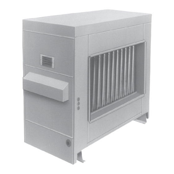
Outdoor duct furnace
Hide thumbs
Also See for RP:
- Installation operation & maintenance (28 pages) ,
- Installation, operation and maintenance manual (40 pages)
Table of Contents
Advertisement
Quick Links
INSTALLATION/OPERATION/MAINTENANCE FOR OUTDOOR
DUCT FURNACE
RP
• Failure to follow safety warnings exactly could result in serious injury, death, or property
damage.
• Improper installation, adjustment, alteration, service, or maintenance can cause serious injury,
death, or property damage.
• Installation and service must be performed by a qualified installer, service agency, or the gas
supplier.
• Do not store or use gasoline or other flammable vapors and liquids in the vicinity of this or
any other appliance.
• Do not try to light any appliance.
• Do not touch any electrical switch; do not use any phone in your building.
• Leave the building immediately.
• Immediately call your gas supplier from a neighbor's phone. Follow the gas supplier's
instructions.
• If you cannot reach your gas supplier, call the fire department.
DO NOT DESTROY. PLEASE READ CAREFULLY. KEEP IN A SAFE PLACE FOR FUTURE REFERENCE.
Supersedes: I-RP-HRPD (05-16) PN132210R16
MODELS RP AND HRPD
⚠ DANGER ⚠
FIRE OR EXPLOSION HAZARD
WHAT TO DO IF YOU SMELL GAS
Revision: I-RP-HRPD (04-21) 132210-A
HRPD
Advertisement
Table of Contents

Related Manuals for Reznor RP


Summary of Contents for Reznor RP
- Page 1 Revision: I-RP-HRPD (04-21) 132210-A Supersedes: I-RP-HRPD (05-16) PN132210R16 INSTALLATION/OPERATION/MAINTENANCE FOR OUTDOOR DUCT FURNACE MODELS RP AND HRPD HRPD ⚠ DANGER ⚠ FIRE OR EXPLOSION HAZARD • Failure to follow safety warnings exactly could result in serious injury, death, or property damage.
-
Page 2: Table Of Contents
6.2 High Elevation (>2,000 Feet/609 Meters) 10.3 Troubleshooting ........29 Installations ..........9 APPENDIX ............. 30 6.3 Conversion to LP (Propane) ....10 Converting Model RP Duct Furnace for 6.4 Venting ............11 Lower Temperature Rise and igher CFM 6.5 Duct Furnace Airflow ......12 Application ............30 7.0 Electrical Supply and Connections .... -
Page 3: General Installation Information
Installation should be done by a qualified agency in accordance with the instructions in this manual and in compliance with all codes and requirements of authorities having Installation jurisdiction. The instructions in this manual apply to duct furnace Model RP and Model Information HRPD. -
Page 4: Uncrating And Preparation
Check to see if there are any field-installed options that need to be assembled to the furnace prior to installation. 3.2.2 Instructions for Model RP duct furnaces are equipped with directional air baffles between the heat exchanger tubes as shown in FIGURE 1. Facing the control compartment of the Reversing Airflow by furnace, the standard direction of airflow is from left to right. -
Page 5: Dimensions And Clearances
26 (660) 1/4” (6mm) 4-1/16 (103) diameter condensate Rear View Left Side View drain (2 per side) Model Series RP Dimensions - inches ± 1/8 / mm ±3 Gas Connection (inches) Natural Propane 30-15/16 28-1/2 15-1/4 20-5/16 786 648 387... -
Page 6: Clearances
Size HRPD by Size Mounting Models RP, HRPD - These furnaces may be placed directly on a slab or roof where support is adequate. Support rails provide required clearance from combustibles. See mounting requirements in FIGURE 3. I-RP-HRPD (04-21) 132210-A, Page 6... -
Page 7: Mechanical
All components of a gas supply system must be leak tested prior to placing equipment in service. NEVER TEST FOR LEAKS WITH AN OPEN FLAME. Failure to comply could result in personal injury, property damage or death. I-RP-HRPD (04-21) 132210-A, Page 7... - Page 8 Most units require a minimum of 5 IN WC of natural gas as stated above, but Sizes 350 and 400 with electronic modulation require a minimum of 6 IN WC natural gas supply pressure. Sizes 300 and 350 with mechanical modulation require 7 IN WC. I-RP-HRPD (04-21) 132210-A, Page 8...
-
Page 9: High Elevation (>2,000 Feet/609 Meters) Installations
5. Check all connections for gas leaks using commercial leak-detecting fluid or rich soap and water solution. Leaks are indicated by presence of bubbles. If leak is detected, tighten connection. If leak cannot be stopped by tightening connection, replace part(s). I-RP-HRPD (04-21) 132210-A, Page 9... -
Page 10: Conversion To Lp (Propane)
If LP (propane) conversion is required, convert the unit in accordance with form CP-GC Parts available from your Factory Distributor and found at www.reznorhvac.com. When conversion is complete, verify that the input rate is correct. I-RP-HRPD (04-21) 132210-A, Page 10... -
Page 11: Venting
5” Vent Cap, P/N 110052 Support angles for flue pipe. 4’ Recommended size is (1.2M) 1/2”x1/2”, 20 gauge 5” dia Flue Pipe 5” dia 90° Elbow 18” (457mm) Straight Pipe Oval Adapter Assy Combustion Air Intake I-RP-HRPD (04-21) 132210-A, Page 11... -
Page 12: Duct Furnace Airflow
The charts below show the approved temperature rise range with the required CFM and the internal pressure drop for each size of unit. Model RP (80% thermal efficient) Size Temp Rise CFM P.D. CFM P.D. CFM P.D. CFM P.D. CFM P.D. CFM P.D. CFM P.D. CFM P.D. CFM P.D. - Page 13 • Through Masonry Walls - No warm air duct should come in contact with masonry walls. Insulate around all air duct through masonry walls with not less than 1/2 inch (1 inch recommended) of insulation. I-RP-HRPD (04-21) 132210-A, Page 13...
- Page 14 Options AG8, AG9, AG39, and AG41 include a sensor and mixing tube like the one illustrated in FIGURE 10B. Options AG40 and AG42 require a field-supplied sensor. Follow the instructions below to install the sensor in the ductwork. For control information, see Paragraph 8.4. I-RP-HRPD (04-21) 132210-A, Page 14...
-
Page 15: Electrical Supply And Connections
Check the rating plate on the heater for the supply voltage and current requirements. 7.2 Supply Voltage A separate line voltage supply with fused disconnect switch should be run directly from and Wiring the main electrical panel to the furnace, making connection to leads in the junction box. I-RP-HRPD (04-21) 132210-A, Page 15... -
Page 16: Thermostat And Control Wiring
See Hazard Levels, page 2. 24V Controls Maximum Amps (24V Transformer has 20VA capacity) Single-Stage Valve Two-Stage Valve Maxitrol System Spark Ignition System Fan Control Coil 0.12 Time Delay Relay Heater Relay Coil 0.12 I-RP-HRPD (04-21) 132210-A, Page 16... -
Page 17: Wiring Diagrams
The heater is equipped with a non-adjustable high limit switch that shuts off the gas in the event of motor failure, lack of air due to dirty filters, or restrictions at the inlet or outlet of the unit. See Paragraph 9.3 for limit control check. I-RP-HRPD (04-21) 132210-A, Page 17... -
Page 18: Combustion Air Proving Switch
The first method, identified by Options AG3 or AG15 is applicable to both Model RP and HRPD and is comparable to the two-stage heating units. Instead of control from a two-stage room thermostat, the discharge air temperature is monitored and the two-stage gas valve is controlled by a two-stage ductstat. - Page 19 Optional Ductstat with Electronic Remote Setpoint Module (Options AG15 and AG17 ) - These two-stage makeup air options that are controlled from a sensing probe with a remote electronic temperature selector that has a temperature operating range I-RP-HRPD (04-21) 132210-A, Page 19...
- Page 20 AG9 is identified as MV4; AG21 is identified as MVA; AG39 is identified as MP1; and AG40 is identified as MP2. AG39 and AG40 are available only on Model RP. AG41 is identified as MP3 and AG42 is identified as MP4. Both AG41 and AG42 apply to Model HRPD.
- Page 21 When the input rate is reduced enough to decrease the gas pressure to 1.1 IN WC, the primary gas pressure switch I-RP-HRPD (04-21) 132210-A, Page 21...
- Page 22 "on" positions, the conditioner accepts a 4-20 milliamp signal. In the "off" positions, the conditioner accepts a 0-10V signal. The conditioner converts the signal to the 0 to 20 volt DC current required to control the modulating valve. I-RP-HRPD (04-21) 132210-A, Page 22...
-
Page 23: Pilot And Ignition Systems
Proper operation of the electronic spark ignition system requires a minimum flame signal of .2 microamps as measured by a microampmeter. With pilot flame proven, the ignition controller energizes the main gas valve. I-RP-HRPD (04-21) 132210-A, Page 23... -
Page 24: Burners And Carryover System
When making the adjustment, close the air shutters no more than is necessary to eliminate the problem condition. DANGER Failure to install and/or adjust air shutters according to directions could cause property damage, personal injury, and/or death. I-RP-HRPD (04-21) 132210-A, Page 24... -
Page 25: Commissioning And Startup
The limit control should open within a few minutes, shutting off the gas supply to the main burners. Return all instruction forms and warranty information to the "Owner's Envelope". Keep for future reference. I-RP-HRPD (04-21) 132210-A, Page 25... -
Page 26: Maintenance And Service
1) Locate the 1/8” FPT INLET pressure tap on the combination valve (FIGURE 19). FIGURE 19 - Top View of Gas Valves Two-Stage Single- 1/8” Outlet Valve Pressure Tap Stage Valve 1/8" INLET 1/8” Outlet Pressure Tap 1/8" INLET Pressure Pressure Tap I-RP-HRPD (04-21) 132210-A, Page 26... - Page 27 Use a fine wire to dislodge any stubborn particles in the burner ports. Do not use anything that might change the port size. Clean the burner rack carryover systems with air pressure. I-RP-HRPD (04-21) 132210-A, Page 27...
- Page 28 Rear Baffle Tube exchanger Loosen Baffle Screws surface remove directional air baffles. Remove Screws A Screws "A" and slide baffles out. Clean and Front replace all Baffle Remove Screws baffles. Bottom Baffle Support Screw C I-RP-HRPD (04-21) 132210-A, Page 28...
-
Page 29: Troubleshooting
2. Defective fan control. 2. Replace fan control. During 3. Incorrect manifold pressure. 3. Check manifold line pressure (See Paragraph 6.1). Operation 4. Blower set for too low temperature 4. Slow down blower or increase static pressure. rise. I-RP-HRPD (04-21) 132210-A, Page 29... -
Page 30: Appendix
APPENDIX Converting Model RP Duct Furnace for Lower Temperature Rise and Higher CFM Application WARNING This conversion shall be done by a qualified service agency in accordance with the manufacturer’s instructions and all applicable codes and requirements of the authority having jurisdiction. - Page 31 Converting Model RP Duct Furnace for Lower Temperature Rise and Higher CFM Application (cont'd) Baffles: remove with supports as assembly FIGURE 23 - Discharge Air End of the Heat Exchanger showing the Baffle Assembly to be Removed Remove support bracket...
-
Page 32: Installation Record
If you need additional assistance, contact the Distributor listed above. • For more information, contact your Factory Representative. Specifications and illustrations subject to change without notice or incurring obligations. ©2021 Nortek Global HVAC LLC, O’Fallon, MO. All rights reserved. I-RP-HRPD (04-21) 132210-A...
Need help?
Do you have a question about the RP and is the answer not in the manual?
Questions and answers