Table of Contents
Advertisement
!
WARNING:
FIRE OR EXPLOSION HAZARD
Failure to follow safety warnings exactly could result in serious injury, death, or
property damage.
Be sure to read and understand the installation, operation, and service instructions in
this manual.
Improper installation, adjustment, alteration, service, or maintenance can cause
serious injury, death, or property damage.
— Do not store or use gasoline or other flammable vapors and liquids in the vicinity
of this or any other appliance.
— WHAT TO DO IF YOU SMELL GAS
•
Do not try to light any appliance.
•
Do not touch any electrical switch; do not use any phone in your building.
•
Leave the building immediately.
•
Immediately call your gas supplier from a phone remote from the building. Follow
the gas supplier's instructions.
•
If you cannot reach your gas supplier, call the fire department.
— Installation and service must be performed by a qualified installer, service agency,
or the gas supplier.
®
Installation / Operation / Maintenance
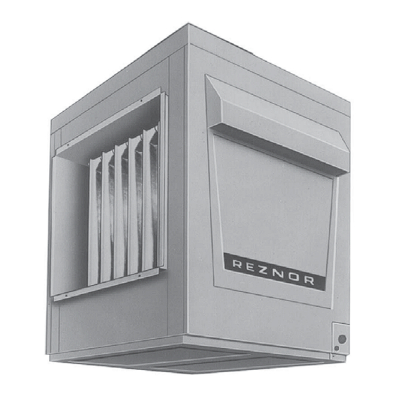
Applies to: Model X
Indoor Duct Furnace
CQS
CQS
Form I-X (Version D)
Obsoletes Form I-X (Version C)
Form I-X, P/N 150491 R7, Page 1
Advertisement
Table of Contents

Related Manuals for Reznor X


Summary of Contents for Reznor X
- Page 1 • If you cannot reach your gas supplier, call the fire department. — Installation and service must be performed by a qualified installer, service agency, or the gas supplier. Form I-X, P/N 150491 R7, Page 1...
-
Page 2: Table Of Contents
Installation should be done by a qualified agency in accordance with the instructions Installation in this manual and in compliance with all codes and requirements of authorities having jurisdiction. Information The instructions in this manual apply to a Model X duct furnace. Form I-X, P/N 150491 R7, Page 2... -
Page 3: Warranty
WARNING: Avoid installing a furnace in extremely drafty areas. Extreme drafts can shorten the life of the heat exchanger and/ or cause safety problems. Form I-X, P/N 150491 R7, Page 3... -
Page 4: Combustion Air Requirements For A Heater Located In A Confined Space
If the furnace has incurred any damage in shipment, document the damage with the transporting agency and immediately contact an authorized Reznor distributor. If you are a Reznor distributor, follow the FOB freight policy procedures as published by Thomas & Betts for Reznor products. -
Page 5: Preparing The Furnace For Installation
Other shipped-separate options could include a vent damper, a power venter, a gas shutoff valve, a condensate drain fitting, a thermostat, and/or a disconnect switch. Model X furnaces are equipped with directional air baffles between the heat exchanger 3.2.1 Instructions for tubes. -
Page 6: Dimensions And Clearances
Required Clearances side of the furnace must be Sides Bottom the width of the furnace plus Control Opposite To Combustibles To Non-Combustibles 6" (152mm). 6" (152mm) See Note 6" (152mm) 3" (76mm) Form I-X, P/N 150491 R7, Page 6... -
Page 7: Suspending Or Mounting The Furnace
Test Pressures Above 1/2 PSI: Disconnect the heater and manual valve from the gas supply line which is to be tested. Cap or plug the supply line. Test Pressures Below 1/2 PSI: Before testing, close the manual valve on the heater. Form I-X, P/N 150491 R7, Page 7... - Page 8 7/8” (22mm) dia. (Not Gas Supply Line Size) 1-7/8” x 1-3/8” (48x35mm) Unit Size 75-250 300-400 Top View 2-3/32” (53mm) Natural Gas 1/2" 3/4" 4” (102mm) 5-5/8” (143mm) Propane 1/2" 1/2" 6-7/8” (175mm) Form I-X, P/N 150491 R7, Page 8...
-
Page 9: Venting
1. Provide a minimum clearance of 18" between the drafthood relief opening and any obstruction. Do not expose the relief opening to wind drafts from any source such Requirements as from an overhead door or adjacent air handling equipment. Form I-X, P/N 150491 R7, Page 9... -
Page 10: Venting (Cont'd)
10 feet (3M). Install a Reznor Option CC1 vent cap on the end of the vent pipe to prevent rain or snow from entering the open end. ((NOTE: When installing a Size 125, run the required 7"... -
Page 11: Duct Furnace Airflow
6ft (1.8M) 8ft (2.4M) 10ft (3.0M) 15ft (4.6M) 20ft (6.1M) 6.2.2 Vent Outlet Size Model X duct furnaces have the following vent outlet size and shape: Model Size 150, 175 200, 225 250, 300 350, 400 Size and Configuration 5" 6"... -
Page 12: Blower Connections
6.0 Mechanical 6.3 Duct Furnace Airflow (cont'd) (cont'd) 6.3.1 Pressure Drop and Temperature Rise by Size (cont'd) Model X - Pressure Drop Table for 80% Thermal Efficient Duct Furnace Size Temp P.D. CFM P.D. CFM P.D. CFM P.D. CFM P.D. CFM P.D. - Page 13 NOTE: Not all capacities are covered in this chart. If allowable CFM of 2210 = 790 your installation is not covered, consult your Reznor 3) Go to the column in the bypass CFM chart that is representative or the factory to determine the appropriate closest to the pressure drop through the heater.
- Page 14 These openings must be acces- sible when the furnace is in service and should be a minimum of 6" x 10" in size so smoke or reflected light may be observed inside the casing to indicate the pres- ence of leaks in the heat exchanger.
-
Page 15: Electrical Supply And Wiring
Single-Stage Valve Fan Control Heater .12A cycling for optimum tempera- Two-Stage Valve .33A Time Delay Relay ture control, set the anticipator Heater Maxitrol System at full load control AMPS. Spark Ignition Relay Coil .12A Form I-X, P/N 150491 R7, Page 15... -
Page 16: Typical Wiring Diagrams
7.0 Electrical 7.4 Typical Wiring Diagrams Supply and NOTE: If a wiring diagram is needed for a Model X with a match lit pilot (manufactured Wiring (cont'd) prior to 10/03), see APPENDIX, page 30. FIGURE 16 - Typical Wiring Diagram for Model X Furnace with Spark Pilot and Single-Stage... - Page 17 FIGURE 17 - Wiring Diagram for Model X Furnace with Spark Pilot and Two-Stage Gas Valve OPERATING SEQUENCE - SET THERMOSTAT SWITCH AT "OFF" POSITION. - THE FOLLOWING CONTROLS ARE SUPPLIED BY REZNOR FOR FIELD INSTALLATION: CONTROL SWITCH NOTES - THE FOLLOWING CONTROLS ARE SUPPLIED AS OPTIONAL EQUIPMENT: THERMOSTAT - TURN ON POWER, MAIN AND PILOT MANUAL GAS VALVES.
-
Page 18: Controls
All furnaces are equipped with a 24-volt combination valve which includes the auto- matic electric on-off valve controlled by the room thermostat, the pressure regulator, and the manual shutoff valve. The standard gas valve allows for single-stage control from a single-stage, 24-volt thermostat. Form I-X, P/N 150491 R7, Page 18... - Page 19 Selector; (B) Stage- the unit and the manufacturer's instructions for wiring Adder Module and installation. There will be one module for selecting temperature and one-stage adder module as illustrated in FIG- URE 20. Form I-X, P/N 150491 R7, Page 19...
-
Page 20: Pilot And Ignition Systems
1-1/4" with pilot adjustment screw in control valve body. Service NOTE: If your Model X heater was manufactured prior to 10/2003, it may have a standing pilot. See wiring diagrams in the APPENDIX, page 30.. - Page 21 When the above conditions are normal and the main gas flow is still off, the ignition controller is probably defective. NOTE: Model X furnaces manufactured prior to 10/2003 may be equipped with a match-lit pilot. Form I-X, P/N 150491 R7, Page 21...
-
Page 22: Burner Carryover System And Air Adjustment
1) Set the thermostat switch at its lowest setting. without lockout, Option 2) Follow lighting instructions. AH2. Check the wiring diagram on the furnace. 3) Set thermostat switch at desired setting. Form I-X, P/N 150491 R7, Page 22... -
Page 23: Check Installation After Startup
COMBUSTION AIR TO ANY HEATER. Indoor units installed in a confined space must be supplied with air for combustion as required by Code and in Paragraph 2.2 of this heater installation manual. MAINTAIN THE VENT SYSTEM IN STRUCTURALLY SOUND AND PROPERLY OPERATING CONDITION. Form I-X, P/N 150491 R7, Page 23... -
Page 24: Maintenance And Service
If the manometer indicates a gas pressure, the field-installed manual gas valve must be replaced or repaired before the combination gas valve can be checked. Form I-X, P/N 150491 R7, Page 24... - Page 25 FIGURE 29, and slide each baffle forward. Use a brush and/or an air hose to remove accumulated dust and grease deposits from the heat exchanger tubes and the baffles. Re-install the baffles by sliding them into the rear slot and replacing the screw. Form I-X, P/N 150491 R7, Page 25...
-
Page 26: Maintenance Procedures (Cont'd)
Slide the front baffle out of the furnace. Front 2) Remove the screws that attach the tube Baffle Remove baffle hold-down plate to the rear flue Screws baffle. 3) Pull the "V" baffles out of the heat exchanger. Form I-X, P/N 150491 R7, Page 26... -
Page 27: Troubleshooting
2. Replace fan control. on Startup; 3. Incorrect manifold pressure. 3. Check manifold line pressure (See Paragraph 6.1.2). during 4. Blower set for too low temperature rise. 4. Slow down blower or increase static pressure. Operation Form I-X, P/N 150491 R7, Page 27... -
Page 28: Appendix
CFM. WARNING: The instructions in this sheet are designed to prepare a Reznor duct furnace for increased air throughput conversion prior to installation. If your duct furnace is installed, for your safety, turn off the gas and the electric before servicing. - Page 29 Step 1. Test for proper operation. Be sure to comply with the air throughputs in the table on page 28. Form I-X, P/N 150491 R7, Page 29...
-
Page 30: Wiring Diagrams For Match-Lit Pilot Discontinued In 2003
Wiring Diagrams for Match-Lit Pilot Discontinued in 2003 APPENDIX (cont'd) FIGURE 30 - For Reference Only, W. D. 113235 for Model X with Standard Match-Lit Pilot and Standard Single-Stage Gas Valve - APPLIES ONLY TO UNITS MANUFACTURED PRIOR TO 10/03. -
Page 31: Index
Duct Connections 13, 14 Mounting the Furnace 7 Ducts tat Control 19 Ductstat with Capillary Tubing Cleaning Pilot 25 (Option AG3) 19 Pilot 20 Ductstat with Electronic Remote Setpoint Module (Option AG15) Pipe joint 8 Form I-X, P/N 150491 R7, Page 31... -
Page 32: Installation Record
BUILDING OWNER OR MAINTENANCE PERSONNEL: For service or repair • Contact the installer listed above. • If you need additional assistance, contact the Reznor Distributor listed above. • For more information, contact your Reznor Representative by calling 800-695-1901. Reznor/Thomas & Betts 150 McKinley Avenue Mercer, PA 16137 www.RezSpec.com...
Need help?
Do you have a question about the X and is the answer not in the manual?
Questions and answers