Advertisement
Quick Links
REQUIRED
MATERIALS:
• Two (2)
Capable Adults
• Garden Hose or Sand
• (2 each) Wrenches and/
or Socket Wrenches
and Sockets.
1/2"
AND/OR
1/2"
• Allen Wrench
1/8"
OPTIONAL TOOLS
AND MATERIALS:
• Large and Small
Adjustable Wrenches
© COPYRIGHT 2017 by Russell Brands, LLC
NOTE:
Position unit at least 6' 7" (2 meters)
from buildings, water and electricity.
For family and domestic use only.
This manual, accompanied by sales receipt, should be saved and kept on hand as a
convenient reference, as it contains important information about your model.
WARNING!
READ AND UNDERSTAND
OPERATOR'S MANUAL
BEFORE USING THIS UNIT.
FAILURE TO FOLLOW
OPERATING INSTRUCTIONS
COULD RESULT IN INJURY
OR DAMAGE TO PROPERTY.
Toll-Free Customer Service Number for U.S: 1-800-558-5234, For Canada: 1-800-284-8339,
For Europe: 00 800 555 85234 (Sweden: 009 555 85234), For Australia: 1300 367 582
Internet Address: www.spalding.com www.spalding.com.au
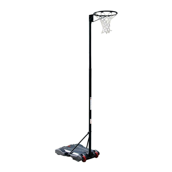
Single Play
Netball System
Adult Assembly Required.
1
Manual
Write Model Number
From Box Here:
WARNING!
NOT SUITABLE
FOR CHILDREN
UNDER THREE
YEARS OF AGE
0-3
DUE TO SMALL
PARTS/CHOKING
HAZARD.
07/17
ID# M760040
Advertisement

Related Manuals for SPALDING AA76100


Summary of Contents for SPALDING AA76100
- Page 1 Toll-Free Customer Service Number for U.S: 1-800-558-5234, For Canada: 1-800-284-8339, • Large and Small For Europe: 00 800 555 85234 (Sweden: 009 555 85234), For Australia: 1300 367 582 Adjustable Wrenches Internet Address: www.spalding.com www.spalding.com.au © COPYRIGHT 2017 by Russell Brands, LLC 07/17 ID# M760040...
-
Page 3: Safety Instructions
SAFETY INSTRUCTIONS FAILURE TO FOLLOW THESE SAFETY INSTRUCTIONS MAY RESULT IN SERIOUS INJURY OR PROPERTY DAMAGE AND WILL VOID WARRANTY. Owner must ensure that all players know and follow these rules for safe operation of the system. To ensure safety, do not attempt to assemble this system without following the instructions carefully. Proper and complete assembly, use, and supervision are essential for proper operation and to reduce the risk of accident or injury. -
Page 4: Parts List
PARTS LIST Item Qty. Part No. Description Base 600069 Axle 208717 266200 Wheel 901285 Strut 203617 Cap, Base 901286 Bottom Pole Section 901287 Lower Middle Pole Section 901288 Upper Middle Pole Section 901289 Top Pole Section 901290 204326 203153 Bolt, Hex, 5/16”-18 X 0.75” 203099 Nut, Nylock, 5/16”-18 600321... - Page 5 PARTS IDENTIFIER - Actual Size #15 (1) #13 (7) #16 (11) 203099Hex Locknut (Nylon Insert) 5/16-18 #17 (2) #18 (3) #12 (4) #19 (1) 203153 hex head bolt 5/16 x 3/4 PARTS IDENTIFIER - Not Actual Size #2 (1) #4 (2) #10 (1) #3 (2) #14 (1) #5 (1) #11 (1) #1 (1)
- Page 6 Get to know the basic parts of your system... TOP POLE MIDDLE POLE (UPPER) MIDDLE POLE (LOWER) BOTTOM POLE STRUTS BASE...
- Page 7 Correctly identify each pole section. SEE BELOW MIDDLE MIDDLE BOTTOM (LOWER) (UPPER)
- Page 8 Align bottom pole (6) with set screw hole towards rear of base. Then assemble bottom pole (6) to base (1) by sliding axle (2) through base (1) and wheels (3) as shown. IMPORTANT! NOTE ORIENTATION. NOTE: SET SCREW HOLE LOCATION FACES TOWARD REAR OF SYSTEM...
- Page 9 Secure base struts (4) to bottom pole (6) using bolt (15) washer (16) and nut (13). Rotate struts down and bend strut outward to line up with hole on base as shown. Secure free end of base strut to base with bolt (17), washer (16), and nut (13) as shown. Repeat for other side.
- Page 10 Insert lower middle pole (7) into bottom pole (6). Align slot and tab to orient the welded nuts to face the rear of system and use set screw (18) to secure in place. IMPORTANT! NOTE ORIENTATION.
- Page 11 Insert top pole (9) into upper middle pole (8). Align slot and tab to orient the welded nut opposite of the top pole’s plate and use set screw (18) to secure in place. Install pole cap (14) into top pole (9) IMPORTANT! NOTE ORIENTATION.
-
Page 12: Outside View
Install rim (10) onto top pole (9) using bolt (12), washer (16) and nut (13) as shown below. Install net (11) on rim (10). OUTSIDE VIEW... - Page 13 Slide the adjustable upper pole assembly (from steps 6-8) into lower middle pole (7). Align holes to face toward rear of system and use thumbscrew (19) to secure in extended position by aligning the dimple with thumbscrew (19). Use the set screw (18) to lock the upper pole assembly in place.
- Page 14 Apply height adjustment label (21) to front of pole as shown. 10 feet (305 cm) Place assembled unit in desired location. Fill base completely with water (7.2 gallons / 27.25 liters) or sand (approx. 60 lb./27.2 kg) and snap base cap (5) in place. NOTE: CAUTION! IF USING SAND:...
Need help?
Do you have a question about the AA76100 and is the answer not in the manual?
Questions and answers