Table of Contents
Advertisement
Available languages
Available languages
Quick Links
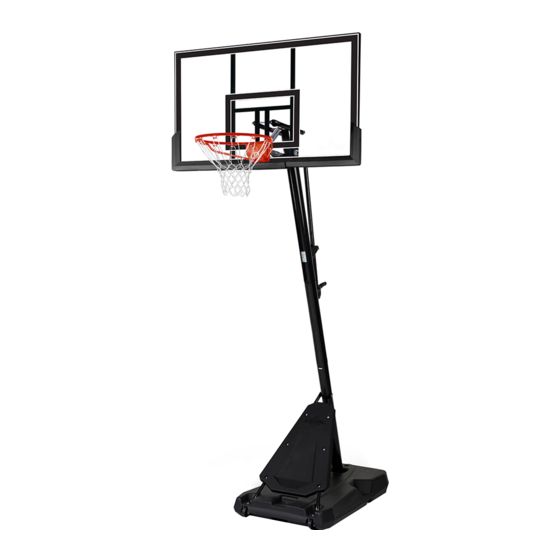
PORTABLE BASKETBALL SYSTEM
Toll-Free Customer Service Number
U.S.:
1-800-558-5234
Canada:
1-800-284-8339
Europe:
+353 51 379777
Australia: 1300 367 582
www.spalding.com
WARNING
READ AND UNDERSTAND THE OPERATOR'S
MANUAL BEFORE USING THIS UNIT.
FAILURE TO FOLLOW THE OPERATING
INSTRUCTIONS COULD RESULT IN INJURY
OR DAMAGE TO PROPERTY.
Owner's Manual
Model Number:
(found on product box)
12/20 ID# M6A11120
ENGLISH
Advertisement
Chapters
Table of Contents

Related Manuals for SPALDING AA6A1355


Summary of Contents for SPALDING AA6A1355
- Page 1 U.S.: 1-800-558-5234 Canada: 1-800-284-8339 Europe: +353 51 379777 Australia: 1300 367 582 www.spalding.com WARNING READ AND UNDERSTAND THE OPERATOR’S MANUAL BEFORE USING THIS UNIT. FAILURE TO FOLLOW THE OPERATING INSTRUCTIONS COULD RESULT IN INJURY OR DAMAGE TO PROPERTY. 12/20 ID# M6A11120...
-
Page 2: Table Of Contents
FAILURE TO FOLLOW OPERATING INSTRUCTIONS COULD RESULT IN INJURY OR PROPERTY DAMAGE. Contact Questions or missing parts? Do NOT go back to the store! warrantyservice@custserv.fotlinc.com Email: Customer Service 1-800-558-5234 Toll-Free Number: Mailing Address: Spalding PO Box 90015 Bowling Green, KY 42102... -
Page 3: Warranty
Warranty Warranty For the very latest Basketball System Warranty information, please visit www.Spalding.com or call Spalding Customer Service at 1-800-558-5234. Safety Information WARNING FAILURE TO FOLLOW THESE SAFETY INSTRUCTIONS MAY RESULT IN SERIOUS INJURY OR PROPERTY DAMAGE AND WILL VOID THE WARRANTY. -
Page 4: Test-Fit Close Tolerance Bolts
Test-Fit Close Tolerance Bolts Test-Fit Close Tolerance Bolts To ensure optimal playability of the backboard system, a close tolerance fit between the elevator components and hardware is required. Test-fit large bolts into large holes of elevator tubes, backboard brackets, and triangle plates. Carefully rock them in a circular motion to remove any excess paint from holes, if necessary. - Page 5 Package Contents KIT 1 – WHEEL ASSEMBLY – 208904 Rod, Axle (x2) Pushnut, 7/16 Shaft Diameter (x4) Bolt, Hex Head, 5/16-18x0.625L (x2) Washer, Flat, 5/16 (x2) KIT 2 – POLE TO BASE ASSEMBLY – 209141 203099Hex Locknut (Nylon Insert) 5/16-18 208505 Washer, Flat, 5/16 (x4) 14 Bolt, Hex Head, 3/8-16x2L (x2)
- Page 6 Package Contents ELEVATOR ASSEMBLY 22 Lift Bracket, Pre-assembly (x1) 23 Handle, Plastic, Pre-assembly (x1) 24 Pin, Locking (x1) 25 Lanyard, Black Coil (x1) 26 Tube for Height Adjustment, Black (x1) KIT 3 – ELEVATOR ASSEMBLY – 209056 203100 NUT, HEX FLANGE, 5/16-18 20 Nut, Hex Flange, 5/16-18 (x2) 27 Reinforcement Plate (x1) 28 Carriage Bolt, 5/16-18x4.25L (x2)
- Page 7 Package Contents KIT 4 – BACKBOARD – 209097 39 Nut, Hex Nylock, 1/2-13 (x5) 40 Spacer, Plastic, 0.75ODx3.25L (x1) 41 Spacer, Plastic, 0.73ODx1.70L (x2) 42 Spacer, Plastic, 0.75ODx0.625L (x4) 43 Nut, Hex Nylock, 3/8-16 (x2) 44 Spacer, Plastic, 0.38IDx0.527L (x4) BACKBOARD HARDWARE (part scaled for page) 36 Bolt, Hex Head, 1/2-13x3.96L(1.25) (x1) 37 Bolt, Hex Head, 1/2-13x7.75L (x4) 38 Bolt, Hex Head, 3/8-16x5.375L (x2)
- Page 8 Package Contents GOAL ASSEMBLY 45 Rim (x1) 46 Cover, Black OR Red (x1) 47 Bracket, Slam Jam, Square, Black (x1) 48 Cap, for Base (x1) 50 Label, Height Adjustment and Moving (x1) 51 Net (x1) 64 Label, Logo (x1) 203617 KIT 5 –...
-
Page 9: Tools & Materials For Assembly
Tools & Materials for Assembly BOARD PAD ASSEMBLY 59 Board Pad, Left Section, Black (x1) 60 Board Pad, Right Section, Black (x1) 61 Board Pad, Center Section, Black (x1) KIT 6 – BOARD PAD HARDWARE – 208909 49 Washer, Flat, 1/4 (x6) 62 Screw, 1/4X1.25 (x2) 63 Screw, 1/4x0.75 (x4) 201596 Screw 1/4 x 1. -
Page 10: Assembly Overview
Assembly Overview Assembly Overview Backboard (Section E, F) Rim (Section G) Elevator System (Section D, E) Top Pole (Section B, C) Bottom Pole (Section B, C) Middle Pole (Section B, C) Base (Section A, C) Front Panel (Section C) Wheel Carriage (Section A) -
Page 11: Assemble The Base
Assemble the Base Assemble the Base Required Parts: Completed Base Assembly: • Kit 1 • Kit 2 • Scrap Wood Board • Socket Wrench or Wrench • Mallet... - Page 12 Assemble the Base ASSEMBLE THE WHEELS 1. Secure the wheel brackets (4) to the wheels (5) using the axles (6) and pushnuts (7). Install each wheel assembly to the base (1) with a single bolt (8) and washer (9). NOTE Do not install both bolts onto the wheel assembly at this time.
- Page 13 WHEN PROPERLY POUNDED TOGETHER, THE POLE SECTIONS SHOULD HAVE A 3 1/2" (9 CM) OVERLAP. IF MINIMUM POLE ENGAGEMENT OVERLAP OF 3 1/2" (9 CM) CANNOT BE ACHIEVED !! STOP !! DO NOT PROCEED TO THE NEXT STEP! - CALL SPALDING CUSTOMER SERVICE AT 1-800-558-5234 FOR ASSISTANCE.
- Page 14 Assemble the Base ASSEMBLE THE OVAL POLE 5. Align the assembled oval pole section with the bottom (10) pole section and slide together. 6. Bounce the assembled sections on a scrap wood board until the overlap reaches the marked line. 3 1/2"...
- Page 15 Assemble the Base INSTALL THE OVAL POLE ONTO THE BASE 1. Attach the oval pole assembly to the base (1). 2. Secure the oval pole assembly to the base (1) using bolts (14) and the pole mounting bracket (13). WARNING TWO PEOPLE ARE REQUIRED FOR THIS PROCEDURE.
- Page 16 Assemble the Base INSTALL THE OVAL POLE ONTO THE BASE 5. Rotate the non-secured ends of the base struts (3) to align with the mounting holes in the base. 6. Secure the ends of the base struts (3) to the wheel brackets (4), with bolts (18) and washers (9).
-
Page 17: Elevator Assembly
Elevator Assembly Elevator Assembly Required Parts: Completed Elevator Assembly: • Kit 3 • Socket Wrench or Wrench PRE-ASSEMBLED HANDLE Label, Height Indicator Label, Height Indicator P/N 204872 P/N 204872 Height Adjustment Rod P/N 901657 26-901607 Screw P/N 208437 Handle, Left P/N 208848 Handle, Right P/N 208849 23-702660 Bracket P/N 901606... - Page 18 Elevator Assembly INSTALL THE ELEVATOR ASSEMBLY 1. Check the three screws on the pre- assembled handle (23) for tightness. 2. Insert the height adjustment tube (26) into the handle pre-assembly (23) and secure with bolts (29) and nuts (30). 3. Install the pre-assembled lift bracket (22) and reinforcement bracket (27) to the top pole (12) with the carriage bolts (28) and nuts (20).
- Page 19 Elevator Assembly INSTALL THE ELEVATOR ASSEMBLY 4. Check the two bolts on the pre-assembled lift bracket (22) for tightness. 5. Connect the end of the pin lanyard (25) to the hole on the bracket (22). 6. Insert the handle assembly through the pole mount assembly.
-
Page 20: Assemble The Backboard
Assemble the Backboard Assemble the Backboard Required Parts: Completed Backboard Assembly: • Kit 4 • Kit 6 • Wrenches and/or Socket Wrenches • Socket Wrench Extension • Phillips Screwdriver • Sawhorse WARNING TWO PEOPLE ARE REQUIRED FOR THIS PROCEDURE. FAILURE TO FOLLOW THIS WARNING COULD RESULT IN SERIOUS INJURY AND/OR PROPERTY DAMAGE. - Page 21 Assemble the Backboard ATTACH THE ELEVATOR TUBE ASSEMBLY 2. While the system is securely resting on the sawhorse, attach both triangle plates (33) to the top pole section (12) using the bolt (36) and nut (39). WARNING TIGHTEN THE BOLTS (36) IN THE LOCK NUTS (39) UNTIL FLUSH (EVEN) WITH THE LOCK NUT’S OUTER EDGE. NOTE TEST-FIT THE LARGE BOLTS INTO THE LARGE HOLES OF THE ELEVATOR TUBES, BACKBOARD BRACKETS, AND TRIANGLE PLATES.
- Page 22 Assemble the Backboard ATTACH THE ELEVATOR TUBE ASSEMBLY 3. Attach the elevator tubes (31 & 32) to the top pole section (12) through the triangle plates (33) using the bolts (37), spacers (42 & 40), and nuts (39). 4. Install the pole cap (35) onto the top pole (12). WARNING TIGHTEN THE BOLTS (37) IN THE LOCK NUTS (39) UNTIL FLUSH (EVEN) WITH THE LOCK NUT’S OUTER EDGE.
- Page 23 Assemble the Backboard ATTACH THE ELEVATOR TUBE ASSEMBLY 5. Attach the handle assembly to the lower elevator tubes (32) using the bolt (37), spacers (41), and nut (39). WARNING TIGHTEN THE BOLT (37) IN THE LOCK NUT (39) UNTIL FLUSH (EVEN) WITH THE LOCK NUT’S OUTER EDGE. NOTE Before moving on to the next step, make sure the adjustable system assembly is set to the 10' (3.05 m) setting.
- Page 24 Assemble the Backboard ATTACH THE ELEVATOR TUBE ASSEMBLY WARNING USE EYE PROTECTION WHEN INSTALLING THE SPRINGS. 6. Attach the lower elevator tubes (32) and counter balance spring (34) to the backboard using the bolt (38), spacers (44), and nut (43). 7.
- Page 25 Assemble the Backboard ATTACH THE ELEVATOR TUBE ASSEMBLY 8. Insert the bolt (37) through the left side of the upper elevator tube (31), then stretch the spring (34) onto the bolt (37). 9. Insert the bolt (37) through the right side of the upper elevator tube (31) and secure with nut (39). IMPORTANT POSITION THE SPRING (34) AGAINST THE ELEVATOR TUBES.
- Page 26 Assemble the Backboard INSTALL THE BOARD PAD 1. Align the left (59), right (60), and center (61) pad sections with the holes in the board. 2. Secure the center (61) board pad in place using the screws (62) and washers (49). IMPORTANT Part #201580 (61) is not used on 44"...
-
Page 27: Assemble The Goal
Assemble the Goal Assemble the Goal Required Parts: Completed Goal Assembly: • Kit 5 • Wrenches and/or Socket Wrenches • Socket Wrench Extension • Phillips Screwdriver ASSEMBLE THE GOAL 1. Insert the t-bolt (52) through the slam jam bracket (47). 2. - Page 28 Assemble the Goal ASSEMBLE THE GOAL 3. Fit the rim (45) securely into the slam jam bracket (47). Allow the t-bolt (52) to slip through the center hole in the rim (45). 4. Install the reinforcement bracket (54) onto the t-bolt (52). 5.
- Page 29 Assemble the Goal ASSEMBLE THE GOAL 6. Install the special nut (53) and washer (56) onto the t-bolt (52). 7. Tighten the nut (53) until 1/8" (3mm) of the bolt threads onto the exposed end of the t-bolt (52). 1/8" (3mm) 8.
- Page 30 Assemble the Goal ASSEMBLE THE GOAL 9. Thread the net (51) onto the rim (45). 10. Apply the Height Adjustment and Moving Label (50) to the front of the pole, where it is clearly visible. 11. While holding the handle, remove the pin (24).
-
Page 31: Fill The Assembled Unit For Use
Fill the Assembled Unit for Use Fill the Assembled Unit for Use Required Parts: Complete Unit Assembly: • Water • Sand WARNING • TWO CAPABLE ADULTS ARE REQUIRED FOR THIS PROCEDURE. FAILURE TO FOLLOW THIS WARNING COULD RESULT IN SERIOUS INJURY. •... - Page 32 Fill the Assembled Unit for Use FILL THE ASSEMBLED UNIT FOR USE 1. Roll the completed assembly to the desired location. 2. Fill the base with water (approx. 34 gallons (128 Liters)) or sand (approx. 300 lbs. (136 kg)). 3. Insert the cap (48) into the base (1) to close.
-
Page 33: Operation
Operation Operation ADJUSTING THE HEIGHT WARNING DO NOT ALLOW CHILDREN TO ADJUST THE HEIGHT. 1. Hold the handle and remove the pin (24). 2. Move the elevator up or down to the desired height. 3. Replace the pin (24) at full length to lock the system at the desired height. -
Page 34: Parts List
Parts List Parts List... - Page 35 Parts List Item Part No . Description Item Part No . Description 600335 Base, Plastic, Black 204838 Spring, Counter Balance 60033701 Ball Return, Plastic, Black 600362 Cap, Plastic, On Top Pole Bolt, Hex Head, 908184 Strut, Steel Tube, Black 209096 1/2-13x3.96L(1.25) 108183 Wheel Bracket, Steel...
- Page 36 Parts List Item Part No . Description Item Part No . Description 206990 Reinforcement Plate 200520 Screw, 8#x3/4L, For Cover 208510 Carriage Bolt, 5/16-18x4.25L 20157801 Board Pad, Left Section, Black 209053 Bolt, Hex, 1/4-20 x 1.77 Long 20157901 Board Pad, Right Section, Black 209054 Nut, Hex Flange, 1/4-20 201580...
- Page 38 In the U.S.: 1-800-558-5234 In Canada: 1-800-284-8339 In Australia: 1-300-367-582 Trademarks registered in the USA and other countries. In the U.S.: 1-800-558-5234 In the U.S.: 1-800-558-5234 In Canada: 1-800-284-8339 ID#: 55679001 02/12 © Copyright 2020 by Russell Brands, LLC www.Spalding.com...
- Page 39 EE. UU.: 1-800-558-5234 Canadá: 1-800-284-8339 Europa: +353 51 379777 Australia: 1300 367 582 www.spalding.com ADVERTENCIA LEA Y COMPRENDA EL MANUAL DEL OPERADOR ANTES DE USAR ESTA UNIDAD. EL INCUMPLIMIENTO DE LAS INSTRUCCIONES DE FUNCIONAMIENTO PODRÍA OCASIONAR LESIONES O DAÑOS MATERIALES.
-
Page 40: Call Toll-Free Customer Service
EL INCUMPLIMIENTO DE LAS INSTRUCCIONES DE FUNCIONAMIENTO PODRÍA OCASIONAR LESIONES O DAÑOS MATERIALES. Contacto ¿Tiene preguntas o le falta alguna pieza? ¡NO vuelva a la tienda! Correo electrónico: warrantyservice@custserv.fotlinc.com Teléfono gratuito del 1-800-558-5234 servicio al cliente: Dirección postal: Spalding PO Box 90015 Bowling Green, KY 42102... -
Page 41: Garantía
Garantía Garantía Para obtener la información más reciente sobre la Garantía del Sistema de Baloncesto, visite www.Spalding.com o llame al Servicio al Cliente de Spalding al 1-800-558-5234. Información de seguridad ADVERTENCIA EL INCUMPLIMIENTO DE ESTAS INSTRUCCIONES DE SEGURIDAD PUEDE OCASIONAR LESIONES GRAVES O DAÑOS MATERIALES Y ANULARÁ... -
Page 42: Comprobación Del Ajuste De Los Pernos De
Comprobación del ajuste de los pernos de tolerancia estrecha Comprobación del ajuste de los pernos de tolerancia estrecha Para garantizar que el sistema del tablero ofrece una calidad de juego óptima, se requiere una estrecha tolerancia del ajuste entre los componentes del elevador y los herrajes. Compruebe el ajuste de los pernos grandes en los orificios grandes de los tubos del elevador, los soportes del tablero y las placas triangulares. - Page 43 Contenido del paquete KIT 1 – MONTAJE DE LA RUEDA – 208904 Núm . 6 Núm . 8 Núm . 7 Núm . 9 Tuerca dentada, diámetro de eje Perno, cabeza hexagonal, 5/16-18 x Varilla, eje (x2) 7/16 (x4) 0.625 de largo (x2) Arandela, plana, 5/16 (x2) KIT 2 –...
- Page 44 Contenido del paquete MONTAJE DEL ELEVADOR Núm . 22 Núm . 23 Núm . 24 Núm . 26 Núm . 25 Soporte de elevación, 23 Manija, de plástico, preensamblada (x1) 24 Pasador, de bloqueo (x1) preensamblado (x1) Tubo para el ajuste de la altura, negro 25 Cordón, negro en espiral (x1) (x1) KIT 3 –...
- Page 45 Contenido del paquete KIT 4 – TABLERO – 209097 Núm . 39 Núm . 43 Núm . 40 Núm . 42 Núm . 44 Núm . 41 Tuerca, Nylock hexagonal, 1/2-13 Espaciador, de plástico, d. ext. 0.75 Espaciador, de plástico, d. ext. 0.73 (x5) x 3.25 de largo (x1) x 1.70 de largo (x2)
- Page 46 Contenido del paquete MONTAJE DE LA CANASTA Núm . 45 Núm . 46 Núm . 47 AJUSTE DE LA ALTURA PARA AJUSTAR EL TABLERO: 1. Quite el pasador mientras sujeta la manija. 2. Mueva el elevador hacia arriba o hacia abajo a la altura deseada. 3.
-
Page 47: Herramientas Y Materiales Para El Montaje
Herramientas y materiales para el montaje Perno, cabeza hexagonal, 5/16-18 x Tornillo, núm. 8 x 3/4 de largo, 1.625 de largo (x4) para cubierta (x2) MONTAJE DE LA ALMOHADILLA DEL TABLERO Núm . 59 Núm . 60 Núm . 61 Almohadilla del tablero, sección Almohadilla del tablero, sección Almohadilla del tablero, sección... -
Page 48: Resumen Del Montaje
Resumen del montaje Resumen del montaje Tablero (Sección E, F) Aro (Sección G) Sistema elevador (Sección D, E) Poste superior (Sección B, C) Poste inferior (Sección B, C) Poste intermedio (Sección B, C) Base (Sección A, C) Panel frontal (Sección C) Carro de ruedas (Sección A) -
Page 49: Montaje De La Base
Montaje de la base Montaje de la base Piezas necesarias: Montaje completo de la base: • Kit 1 • Kit 2 • Tabla de madera de desecho • Llave de vaso o llave • Mazo... - Page 50 Montaje de la base MONTAJE DE LAS RUEDAS 1. Encaje los soportes de las ruedas (4) en las ruedas (5) empleando los ejes (6) y las tuercas dentadas (7). Coloque cada montaje de la rueda en la base (1) con un único perno (8) y una arandela (9).
- Page 51 TENER UNA SUPERPOSICIÓN DE 3 1/2” (9 CM). SI NO PUEDE CONSEGUIR UNA SUPERPOSICIÓN DE ENGANCHE DE 3 1/2” (9 CM), ¡¡PARE!! ¡NO CONTINÚE CON EL SIGUIENTE PASO! - LLAME AL SERVICIO AL CLIENTE DE SPALDING AL 1-800-558-5234 PARA RECIBIR AYUDA.
- Page 52 Montaje de la base MONTAJE DEL POSTE OVALADO 5. Alinee la sección del poste ovalado montada con la sección inferior del poste (10) y encájelas. 6. Empuje las secciones ensambladas sobre el bloque de madera hasta que la superposición alcance la línea marcada. Núm .
- Page 53 Montaje de la base COLOCACIÓN DEL POSTE OVALADO EN LA BASE 1. Conecte el conjunto del poste ovalado a la base (1). 2. Fije el conjunto del poste ovalado en la base (1) utilizando los pernos (14) y el soporte de montaje del poste (13).
- Page 54 Montaje de la base COLOCACIÓN DEL POSTE OVALADO EN LA BASE 5. Gire los extremos no fijados de los puntales de la base (3) para alinearlos con los orificios de montaje de la base. 6. Fije los extremos de los puntales de la base (3) en los soportes de las Núm .
-
Page 55: Montaje Del Elevador
Montaje del elevador Montaje del elevador Piezas necesarias: Montaje completo del elevador: • Kit 3 • Llave de vaso o llave MANIJA PREENSAMBLADA Etiqueta, indicador de Etiqueta, indicador de altura N/P 204872 altura N/P 204872 Varilla de ajuste de la altura N/P 901657 26-901607 Tornillo N/P... - Page 56 Montaje del elevador COLOCACIÓN DEL MONTAJE DEL ELEVADOR 1. Compruebe el ajuste de los tres tornillos en la manija preensamblada (23). 2. Inserte el tubo de ajuste de altura (26) en Núm . 26 la manija preensamblada (23) y fíjelo con los pernos (29) y las tuercas (30).
- Page 57 Montaje del elevador COLOCACIÓN DEL MONTAJE DEL ELEVADOR 4. Compruebe el ajuste de los dos pernos en el soporte de elevación preensamblado (22). Núm . 22 5. Conecte el extremo del pasador del cordón (25) al orificio del soporte (22). Núm .
-
Page 58: Montaje Del Tablero
Montaje del tablero Montaje del tablero Piezas necesarias: Montaje completo del tablero: • Kit 4 • Kit 6 • Llaves y/o llaves de vaso • Extensión de llave de vaso • Destornillador de estrella • Caballete ADVERTENCIA SE REQUIEREN DOS PERSONAS PARA ESTE PROCEDIMIENTO. EL INCUMPLIMIENTO DE ESTA ADVERTENCIA PODRÍA OCASIONAR LESIONES GRAVES Y/O DAÑOS MATERIALES. - Page 59 Montaje del tablero COLOCACIÓN DEL MONTAJE DEL TUBO ELEVADOR 2. Mientras el sistema está apoyado de forma segura sobre el caballete, coloque las placas triangulares (33) en la sección superior del poste (12) utilizando el perno (36) y la tuerca (39). ADVERTENCIA APRIETE EL PERNO (36) EN LA CONTRATUERCA (39) HASTA QUEDAR PAREJO CON EL BORDE EXTERIOR DE LA CONTRATUERCA.
- Page 60 Montaje del tablero COLOCACIÓN DEL MONTAJE DEL TUBO ELEVADOR 3. Conecte los tubos del elevador (31 y 32) en la sección superior del poste (12) a través de las placas triangulares (33) utilizando los pernos (37), los espaciadores (42 y 40) y las tuercas (39). 4.
- Page 61 Montaje del tablero COLOCACIÓN DEL MONTAJE DEL TUBO ELEVADOR 5. Fije el montaje de la manija en los tubos del elevador inferiores (32) utilizando el perno (37), los espaciadores (41) y la tuerca (39). ADVERTENCIA APRIETE EL PERNO (37) EN LA CONTRATUERCA (39) HASTA QUEDAR PAREJO CON EL BORDE EXTERIOR DE LA CONTRATUERCA.
- Page 62 Montaje del tablero COLOCACIÓN DEL MONTAJE DEL TUBO ELEVADOR ADVERTENCIA CUANDO INSTALE LOS RESORTES UTILICE GAFAS PROTECTORAS. 6. Fije los tubos del elevador inferiores (32) y el resorte de contrapeso (34) en el tablero utilizando el perno (38), los espaciadores (44) y la tuerca (43). Núm .
- Page 63 Montaje del tablero COLOCACIÓN DEL MONTAJE DEL TUBO ELEVADOR 8. Introduzca el perno (37) en el lado izquierdo del tubo del elevador superior (31), y después estire el resorte (34) hacia el perno (37). 9. Introduzca el perno (37) en el lado derecho del tubo del elevador superior (31) y fíjelo con la tuerca (39).
- Page 64 Montaje del tablero COLOCACIÓN DE LA ALMOHADILLA DEL TABLERO 1. Alinee las secciones izquierda (59), derecha (60) y central (61) de la almohadilla con los agujeros del tablero. 2. Fije la almohadilla central (61) del tablero en el lugar indicado utilizando tornillos (62) y arandelas (49).
-
Page 65: Montaje De La Canasta
Montaje de la canasta Montaje de la canasta Piezas necesarias: Montaje completo de la canasta: • Kit 5 • Llaves y/o llaves de vaso • Extensión de llave de vaso • Destornillador de estrella MONTAJE DE LA CANASTA 1. Inserte el perno en T (52) a través del soporte slam jam (47). 2. - Page 66 Montaje de la canasta MONTAJE DE LA CANASTA 3. Fije firmemente el aro (45) en el soporte slam jam (47). Deje que el perno en T (52) se deslice a través del orificio central en el aro (45). Núm . 45 Núm .
- Page 67 Montaje de la canasta MONTAJE DE LA CANASTA 6. Instale la tuerca especial (53) y la arandela (56) en el perno en T (52). Núm . 53 Núm . 56 Núm . 52 7. Apriete la tuerca (53) hasta 1/8" (3 mm) Núm .
- Page 68 Montaje de la canasta MONTAJE DE LA CANASTA 9. Enganche la red (51) en el aro (45). Núm . 51 Núm . 51 Núm . 45 Núm . 45 Núm . 51 Núm . 45 Núm . 51 Núm . 45 10.
-
Page 69: Llenado De La Unidad Montada Para Su Uso
Llenado de la unidad montada para su uso Llenado de la unidad montada para su uso Piezas necesarias: Montaje completo de la unidad: • Agua • Arena ADVERTENCIA • SE REQUIEREN DOS ADULTOS CAPACES PARA ESTE PROCEDIMIENTO. EL INCUMPLIMIENTO DE ESTA ADVERTENCIA PODRÍA OCASIONAR LESIONES GRAVES Y/O DAÑOS MATERIALES. - Page 70 Llenado de la unidad montada para su uso LLENADO DE LA UNIDAD MONTADA PARA SU USO 1. Mueva el conjunto completado a la Núm . 48 ubicación deseada. 2. Llene la base con agua (aprox. 34 galones (128 litros)) o arena (aprox. 300 libras (136 kg)).
-
Page 71: Funcionamiento
Funcionamiento Funcionamiento AJUSTE DE LA ALTURA ADVERTENCIA NO PERMITA QUE LOS NIÑOS AJUSTEN LA ALTURA. 1. Sujete la manija y quite el pasador (24). 2. Mueva el elevador hacia arriba o hacia abajo hasta alcanzar la altura deseada. 3. Ajuste la longitud del pasador (24) para fijar el Núm . -
Page 72: Listado De Piezas
Listado de piezas Listado de piezas... - Page 73 Listado de piezas Artículo Cant . Núm . de Descripción Artículo Cant . Núm . de Descripción pieza pieza 600335 Base, de plástico, negra 204838 Resorte, de contrapeso Retorno de pelota, de plástico, Tapa, de plástico, en poste 60033701 600362 negro superior Perno, cabeza hexagonal, 1/2-13...
- Page 74 Listado de piezas Artículo Cant . Núm . de Descripción Artículo Cant . Núm . de Descripción pieza pieza Tornillo, núm. 8 x 3/4 de largo, 206990 Placa de refuerzo 200520 para cubierta Perno de carruaje, 5/16-18 x Almohadilla del tablero, sección 208510 20157801 4.25 de largo...
- Page 75 3. Mueva el sistema de baloncesto hasta la ubicación deseada. 4. Con cuidado, vuelva a poner el sistema de baloncesto en posición vertical. 5. Compruebe que el sistema está estable. SP500072 04/20 © Copyright 2020 de Russell Brands, LLC www .Spalding .com...
Need help?
Do you have a question about the AA6A1355 and is the answer not in the manual?
Questions and answers