
Related Manuals for TMG ST2030


Summary of Contents for TMG ST2030
- Page 1 W W W . T M G I N D U S T R I A L . C O M P 0 / 1 6 T o l l F r e e : 1 - 8 7 7 - 7 6 1 - 2 8 1 9...
-
Page 2: Main Specifications
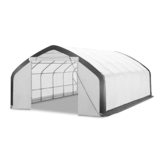
Main Specifications : Overall assembled size : W6 x L9 x H3.65 (m) / 20 x 30 x 12 (ft) Shoulder height : 2 (m) / 6.6 (ft) Front roll up door : 3 x 3 (m) / W10 x H10 (ft) Prior to assembly Please read the instructions carefully before installation. - Page 3 TMG-ST2030 Part List Parts Graphical Description code Peak arch tube Upper rafter tube (middle truss) Upper rafter tube (front truss) Upper rafter tube (rear truss) Shoulder tube (middle truss) Shoulder tube (front and rear truss)
- Page 4 Door column baseplate (front truss) Middle column baseplate (rear truss) Middle truss baseplate Ratchet Door frame lower tube (front and rear truss) Door frame upper tube (front and rear truss) Rear frame middle tube Door frame horizontal tube (front and rear truss) Door frame horizontal tube (rear truss) Ceiling cross bar...
- Page 5 Bottom tension bar (front and rear cover) Bottom tension bar (rear cover) Diagonal bracing bar (1st and last span) Tube clamp Top cover tension tube (for both bottom sides) groups Door dropping tube groups Expansion bolt M12x100mm (not included) Half round head bolt M10x80mm Hex Bolt M10x70mm Hex Bolt...
- Page 6 Nylon rope Water plug Top cover Front cover panel Rear cover panel Braided rope bundle Ratchet straps Scratch resistant tape P 5 / 1 6 W W W . T M G I N D U S T R I A L . C O M T o l l F r e e : 1 - 8 7 7 - 7 6 1 - 2 8 1 9...
- Page 7 Mark the ground in the final building location with a line showing the positions of base plates, front, and rear doors. All lines should be drawn from center to center of all baseplate tubes. Diagonal line X must be equal to Y. Baseplates: all baseplates must be installed firmly with expansion bolts (#16) on this ...
- Page 8 (2) Sidewall tube (#4) (1) Ceiling cross bar (#11) (2) Hex bolt (#19) (12) Hex bolt (#18) (1) Two wheel rope pulley (#11A) (1) One wheel rope pulley (#11B) Picture 2 Parts used to install the rear truss in this step (refer to Picture 3) : ...
- Page 9 Picture 3 Parts used to install (5) middle trusses in this step (refer to Picture 4). (1x5) Peak arch tube (#1) (2x5) Upper rafter tube (#2) (2x5) Shoulder tube (#3) (2x5) Sidewall tube (#4) (1x5) Ceiling cross bar (#11) (2x5) Hex bolt (#19) (12x5) Hex bolt (#18) Picture 4...
- Page 10 Step 3 : Put up the front (1st) truss Use of a crane or forklift is recommended, otherwise a team can use ropes to lift • the trusses, but you have to make sure it is safe, and have enough manpower. We recommend 3 to 5 people to pull the truss up from different directions.
- Page 11 Picture 7 Step 5 : Install the diagonal bracing bars (#13) Connect diagonal bracing bar (#13) on the first and last span between the shoulder tube and sidewall tube (#3A and #4) with tube clamp (#13A), use bolt (#19A) (Picture 8). Parts used in this step : ...
- Page 12 Step 6 : Install the remaining parts on the front truss (Picture 9) Parts used in this step : (2) Door frame upper tube (#9) (2) Door frame lower tube (#8) (2) Door frame horizontal tube (#10) (2) Bottom tension bar (#12) (8) Hex bolt (#18) (4) Hex bolt (#19) Picture 9...
- Page 13 Picture 10 Step 8 : Install front cover panel The door cover must be zipped. Use rope (#24) to lift up the front and rear cover • (#23) from the center grommet and tie it firm to the truss tube and spread toward both sides through each grommet along the tube.
- Page 14 (Picture 11 - view from inside) (Picture 12-view from outside) Step 9 : Install rear cover panel Use rope (#24) to lift up the rear cover (#23A) from the center grommet and tie it firmly to the truss tube and spread toward both sides through each grommet along the tube (Picture 13).
- Page 15 Picture 13 Step 10 : Install the top cover (#22) Do not install the cover during windy weather! Unpack the top cover and place it along one of the long sides of the structure. • Use 3 to 5 ropes (#24) to pull the cover over the top of the structure, 2 or 3 people •...
- Page 16 Step 11 : Stretch and tighten top cover The roof cover must be stretched and tied to the front and rear truss by rope going • through the flap grommets on the cover. Start from the top center and go toward both sides on each end.
- Page 17 Step 13 : Install ratchet straps (Picture 17) Stretch and adjust the cover from left and right, back and forth, to make sure it is square and centered. Cut the groove pocket where it aligns with ratchet (#7A), and use strap (#25) to pull tension tube (#14) toward the ratchet and tie it firmly there.
Need help?
Do you have a question about the ST2030 and is the answer not in the manual?
Questions and answers