Table of Contents

Subscribe to Our Youtube Channel
Related Manuals for CPI 3180 Series

Summary of Contents for CPI 3180 Series
- Page 1 4096-668 October 01, 2020 ASSEMBLY MANUAL Revision D Assembly Instruction for Series 3180 1.8M Ka-Band Antenna SATCOM & Antenna Technologies, Inc. 1700 Cable Drive NE Conover, NC 28613 USA t +1 704-462-7330 f +1 704-462-7380 www.cpii.com...
- Page 2 4096-668 CPI Satcom & Antenna Technologies 1.8M Ka-BAND Rx/Tx ANTENNA 1.8M Ka-BAND Rx/Tx SERIES 3180 ANTENNA SYSTEM Updated to CPI format. 10/01/20 R.F. Add Conover Address 6/1/16 Revised and updated. 03/22/12 R.F. Revised Company Name and Logo 6/1/09 ORIGINAL RELEASE 8/25/04 REV.
-
Page 3: Table Of Contents
4096-668 CPI Satcom & Antenna Technologies 1.8M Ka-BAND Rx/Tx ANTENNA TABLE OF CONTENTS SECTION TITLE GENERAL INFORMATION Introduction Unpacking And Inspection Freight Damage Missing Or Damaged Material Suggested Tool List Mechanical Alignment Tools Site Selection Suggested Mast & Foundation ANTENNA SYSTEM... - Page 4 4096-668 CPI Satcom & Antenna Technologies 1.8M Ka-BAND Rx/Tx ANTENNA...
-
Page 5: General Information
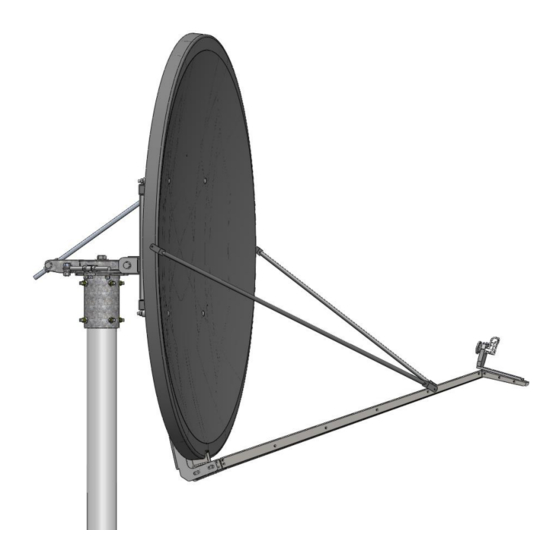
This manual describes the assembly and installation of CPI’s 1.8M antenna system with Az/El mount. The CPI 1.8M is a rugged, reliable antenna system, which will operate with high efficiency and at the same time successfully withstand the effects of the environment. The basic 1.8M antenna consists of an offset reflector, reflector support, feed support structure and Az/El positioner. -
Page 6: Suggested Tool List
4096-668 CPI Satcom & Antenna Technologies 1.8M Ka-BAND Rx/Tx ANTENNA SUGGESTED TOOL LIST The following tools are suggested for the antenna installation. HARDWARE SIZE SAE WRENCH SIZE METRIC WRENCH MAXIMUM REC. SIZE TORQUE 7/16" 11mm 6.5 ft-lbs 1/4" BOLT 5/16" BOLT 1/2"... -
Page 7: 1.7 Suggested Mast & Foundation
The antenna should be properly grounded to meet applicable local codes. Minimum depth as shown or extend to local frost line. (CPI DOES NOT REPRESENT OR WARRANT THAT ANY PARTICULAR DESIGN OR SIZE OF FOUNDATION IS APPROPRIATE FOR ANY LOCALITY OR EARTH STATION INSTALLATION.) - Page 8 4096-668 CPI Satcom & Antenna Technologies 1.8M Ka-BAND Rx/Tx ANTENNA SECTION II ANTENNA ASSEMBLY PARTS LIST - 1.8M ANTENNA PARTS LIST ITEM PART NO. DESCRIPTION VARIES 1.8M REFLECTOR 0490-814 REFLECTOR SUPPORT 0185-358 ASSEMBLY, 1.8M Az/El 0185-357 ASSEMBLY, 1.8M ELEVATION ADJ. ROD...
-
Page 9: Antenna Assembly
4096-668 CPI Satcom & Antenna Technologies 1.8M Ka-BAND Rx/Tx ANTENNA 2.0 ANTENNA ASSEMBLY Follow the steps below in the order shown to assemble the antenna. Because of the weight and size of some of the antenna components, a minimum two person crew is recommended. Do not tighten any hardware until instructed to do so. - Page 10 4096-668 CPI Satcom & Antenna Technologies 1.8M Ka-BAND Rx/Tx ANTENNA Installing the reflector support 1. Lift the reflector support (Item #2) and position the two mounting plates onto the AZ/El assembly. Look for the elevation mounting bracket and ensure that it is rotated to the top of the reflector support.
- Page 11 4096-668 CPI Satcom & Antenna Technologies 1.8M Ka-BAND Rx/Tx ANTENNA 3. Attach the elevation adjustment rod (Item #4) to the elevation mounting bracket of the reflector support with the elevation pivot sleeve, ½-13 x 1.75-inch bolt, two flat washers, and hex nut (Items #6, 8, 9, 10, 11).
- Page 12 4096-668 CPI Satcom & Antenna Technologies 1.8M Ka-BAND Rx/Tx ANTENNA 6. Attach the tailpiece support bracket (Item #5) to the reflector support by using (2) 5/16 x 5.50-inch bolts, (4) 5/16-inch flat washers, (2) 5/16-inch lock washers and (2) 5/16-inch hex nuts (Items #16, 17, 18, 19).
- Page 13 4096-668 CPI Satcom & Antenna Technologies 1.8M Ka-BAND Rx/Tx ANTENNA Attaching the reflector 1. Orient the reflector (Item #1) so that the feed support pocket is at the bottom. 2. Lift the reflector and position onto the reflector support. 3. Attach by inserting a 1/2-13 x 6.00-inch carriage bolt (Item #7) through each of the four holes in the reflector from the front to the back and through the mounting holes of the reflector support.
-
Page 14: Feed And Feed Support Assembly
4096-668 CPI Satcom & Antenna Technologies 1.8M Ka-BAND Rx/Tx ANTENNA SECTION III FEED AND FEED SUPPORT ASSEMBLY These instructions are intended as a general reference for feed and feed support assembly. If your antenna system has specific feed or feed support installation instructions, please refer to them at this time. - Page 15 4096-668 CPI Satcom & Antenna Technologies 1.8M Ka-BAND Rx/Tx ANTENNA Attaching the feed support 1. Place the feed support (Item #2) between the mounting ears of the tailpiece and into the pocket at the bottom of the reflector. 2. Insert a 5/16-18 x 1.00-inch bolt and flat washer (Items #5, 7) through the hole in the feed support and the hole in the top of the pocket of the reflector and secure with a flat washer, lock washer and hex nut (Items #7, 8, 9) on the back of the reflector.
- Page 16 4096-668 CPI Satcom & Antenna Technologies 1.8M Ka-BAND Rx/Tx ANTENNA 4. Attach a feed rod to the mounting hole in the side of the reflector with a 5/16-18 x 1.00-inch bolt and flat washer (Items #5, 7) and secure with a flat washer, lock washer, and hex nut (Items #7, 8, 9) on the back side of the reflector.
- Page 17 4096-668 CPI Satcom & Antenna Technologies 1.8M Ka-BAND Rx/Tx ANTENNA 7. Tighten securely the three 5/16-inch bolts used to attach the feed system to the reflector and the 5/16-inch bolt used to attach the feed rods to the feed support at this time.
-
Page 18: Antenna Pointing
1.8M Ka-BAND Rx/Tx ANTENNA SECTION IV ANTENNA POINTING Alignment To Satellite CPI’s 1.8 meter Az/El mount requires that the antenna be aligned to the satellite orbital arc initially by a trained installer. Initial Alignment The 1.8 meter offset reflector contains a 17.35 elevation offset look angle. - Page 19 4096-668 CPI Satcom & Antenna Technologies 1.8M Ka-BAND Rx/Tx ANTENNA Inclinometer FIGURE 4.1...
-
Page 20: Maintenance
Check for corrosion - on the reflector structure and mount. Reflector CPI’s reflector does not require any maintenance. The composite construction of the reflector is virtually impervious to any damages that could be caused by weather or other atmospheric conditions. -
Page 21: Mount And Reflector Support
4096-668 CPI Satcom & Antenna Technologies 1.8M Ka-BAND Rx/Tx ANTENNA Mount And Reflector Support Structure The mount and reflector support structure supplied with this antenna is of steel construction and has a hot-dipped galvanized finish. If inspection shows any signs of structural failure, the mount members that are damaged should be repaired or replaced.
Need help?
Do you have a question about the 3180 Series and is the answer not in the manual?
Questions and answers