Advertisement
INSTALLATION AND MAINTENANCE INSTRUCTIONS
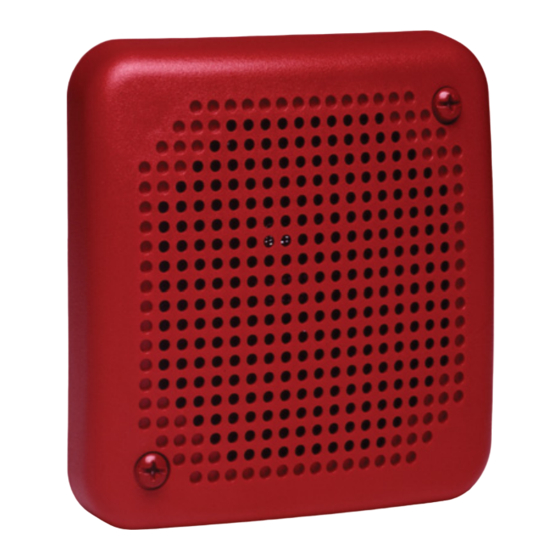
SpectrAlert SP200 Series
Dual Voltage Transformer Speakers
for Fire Protective Signaling Systems
For use with the following models: SP200W, SP201R, SP201W
U.S. patent number: D424465
Specifications
Input Terminals:
Speaker Size:
Grille Size
Round:
Square:
Electrical
Voltage Input:
Frequency Range:
Operating Temperature Range:
Power:
Listings:
NOTICE: This manual shall be left with the owner/user of
this equipment.
General Description
The National Fire Protection Association (NFPA) has pub-
lished standards and recommended practices for the speak-
ers described in this manual. As a result, the installer must
be familiar with these requirements as well as all local
codes and special requirements of the authority having
jurisdiction.
SP200 series speakers can be operated with distribution
amplifiers having an output voltage of either 25 volts or
70.7 volts.
The speakers operate at any one of four input power levels.
The output sound level is selected at the time of installa-
tion, but can be changed, if necessary.
The speaker is also equipped with a capacitive input to
allow for DC supervision.
Installation
All wiring must be installed in compliance with the National
Electrical Code (NEC) and applicable local codes as well as
special requirements of the authority having jurisdiction,
using the proper wire size. This also includes all applicable
NFPA Standards, ANSI/UL 1480, and NEC 760.
Electrical
1. Connect the speaker as shown in Figure 1.
NOTE: Do NOT loop electrical wiring under terminal screws.
Wires connecting the device to the control panel
must be broken at the device terminal connection
in order to maintain electrical supervision.
D400-69-00
12 to 18 AWG (3.31 to 0.82 mm
4 inches (101 mm)
6
7
/
" (187 mm)
8
7
4
/
" (127 mm)
8
25 volts or 70.7 volts (nominal)
400 – 4000 Hz
32° to 120°F (0° to 49°C)
1
/
,
1
/
, 1 and 2 Watts
4
2
UL S4048
1
3825 Ohio Avenue, St. Charles, Illinois 60174
2
)
Figure 1. Electrical connections:
INPUT FROM
AMPLIFIER
2. See Figure 2 as an example of how to select a
input when a 25 volt amplifier is being used. Notice that
the header, SW1, has two shunts. One shunt is used to
select either 25 or 70.7 volts input. The other shunt is
used to select input power of
Figure 2:
CORRECT
25.0V
70.7V
2W
1W
1/2W
1/4W
800/736-7672, FAX: 630/377-6495
www.systemsensor.com
TO NEXT
SPEAKER OR EOL
1
/
Watt
4
1
/
,
1
/
, 1 or 2 Watts.
4
2
INCORRECT
25.0V
70.7V
2W
1W
1/2W
1/4W
I56-1217-007R
Advertisement
Table of Contents

Related Manuals for System Sensor SpectrAlert SP200 Series


Summary of Contents for System Sensor SpectrAlert SP200 Series
- Page 1 INSTALLATION AND MAINTENANCE INSTRUCTIONS SpectrAlert SP200 Series Dual Voltage Transformer Speakers 3825 Ohio Avenue, St. Charles, Illinois 60174 800/736-7672, FAX: 630/377-6495 for Fire Protective Signaling Systems www.systemsensor.com For use with the following models: SP200W, SP201R, SP201W U.S. patent number: D424465...
- Page 2 Please refer to insert for the Limitations of Fire Alarm Systems Three-Year Limited Warranty System Sensor warrants its enclosed speaker to be free from defects in #__________, 3825 Ohio Avenue, St. Charles, IL 60174. Please include materials and workmanship under normal use and service for a period a note describing the malfunction and suspected cause of failure.
Need help?
Do you have a question about the SpectrAlert SP200 Series and is the answer not in the manual?
Questions and answers