
Related Manuals for AGCO HayBoss G2 445, HayBoss G2 450


Summary of Contents for AGCO HayBoss G2 445, HayBoss G2 450
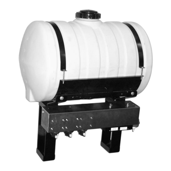
- Page 1 Installation Manual Model 445, 450 & 451 25 & 55 gallon Automatic Preservative Applicator Forage Harvester #010-445-451-450-INST Revised 5/22...
-
Page 3: Table Of Contents
Drain fill kit (450 & 451 only) Model 451 base kit Pump manifold Star wheel sensor, bale rate sensor, & hoses Control box and harnesses Baler specific installation kits 33-39 Notes Star Wheel Template 4415B Guide WARRANTY STATEMENT For AGCO part cross-reference visit: www.harvesttec.com/system.html... -
Page 4: Introduction
55 gallon Tools Needed Standard wrench and socket set Standard screwdriver set Side cutter Hose cutter Crescent wrench Hammer Metal drilling and cutting tools Tape measure Center punch 1-1/2” hole saw (4415B only) Straight edge For AGCO part cross-reference visit: www.harvesttec.com/system.html... -
Page 5: Installation Of Applicator
Installation of Applicator 1. Installation of Mounting Brackets, Tank, Pump Manifold and Hose Manifold (450 & 445 only) Model 445 Figure 1 Mount the unit on the diagonal frame behind the twine box, as pictured using the base clamp (001- 4406) and u-bolts (001-4406A). - Page 6 3/8 x 1 1/4 bolts, nuts, locks, and flat washers to the U shaped bracket (001-4647). Install the rest of the pump plate as shown in Figure 6. Attach the pump plate holder (001-4646D) to pump plate mounting bracket (001-4646C) using four 3/8 x 3/4 flange head bolts. For AGCO part cross-reference visit: www.harvesttec.com/system.html...
-
Page 7: Model 450
Secure the allen head carriage bolts with 1/2 nuts, flat and lock washers. Mount the supplied support bracket to the bottom of the tank saddle and to the baler frame as shown below. Figure 1 Mount support bracket (001-4424C) at these locations. Two tie models only. For AGCO part cross-reference visit: www.harvesttec.com/system.html... - Page 8 3. Connect the pump plate mounting bracket (001-4646C), shown in Figure 2, using two 3/8 x 1 1/4 bolts, nuts, locks, and flat washers to the saddle. 4. Attach the pump plate holder (001-4646D) to pump plate mounting bracket (001-4646C) using four 3/8 x 3/4 flange head bolts. Figure 3. For AGCO part cross-reference visit: www.harvesttec.com/system.html...
-
Page 9: Model 445 & 450
Mount the hose manifold on the front of the baler in the area of the spray shield. Make sure the bracket will not interfere with any baler operations. Hose Hose manifold manifold AGCO & CASE INLINE BALERS NEW HOLLAND & CASE SBX WITH 4409 INSTALL KIT For AGCO part cross-reference visit: www.harvesttec.com/system.html... -
Page 10: Model 451
001-4402 001-4647 Front of 001-4646C Baler 001-4646D 2” (5 cm) dia hole through side 001-4703CD Bolt to bottom side 001-4703CC 001-4703C Bolt to bottom side For AGCO part cross-reference visit: www.harvesttec.com/system.html... -
Page 11: Placement Of Spray Nozzle Assembly
Three 1/4 inch lines will need to be run from the hose manifold to the spray shield. Use the color- coded stickers to attach the correct hose to the correct tips, and couplers. Secure the lines to the bracket and spray shield using the supplied hose clamps. For AGCO part cross-reference visit: www.harvesttec.com/system.html... -
Page 12: Install Kit 4415B
1/4" hole through both top and bottom of the hay guard. 3. Bolt the bottom bracket (001-4425B) using 1/4" x 2” button head cap screw. Secure with a 1/4" flange nut. The head will need to be down (in the chamber). For AGCO part cross-reference visit: www.harvesttec.com/system.html... - Page 13 13. Install the hoses on to the correct pumps. See plumbing section. 1-1/2" hole Brackets Hay Guard 001-4425B Spray Shield Location of first rotating tine View from behind the twine box with the inspection door open. For AGCO part cross-reference visit: www.harvesttec.com/system.html...
-
Page 14: Install Kit 4485B
Do not tighten these bolts until the shield is properly aimed. Aim the shield at bottom of the pickup head at the point where stuffer fingers connect with hay (between the two augers) and make sure the bushing is not removed. Once the shield is in place the nuts may be tightened down. For AGCO part cross-reference visit: www.harvesttec.com/system.html... -
Page 15: Install Kit 4506B
Place bracket 001-4703G so pins are facing up and bolt through with 3/8 x 1-1/2" into bracket 001-4703G, through wrap guard, and into threaded holes on baler frame that the bolts were removed from. For AGCO part cross-reference visit: www.harvesttec.com/system.html... -
Page 16: Installation Of Plumbing
(Pump 1 clear/white, Pump 2 green, Pump 3 blue.) Clear hose Green hose Tank Blue hose Check Pump valves manifold Hose manifold Clear hose Green hose Blue hose For AGCO part cross-reference visit: www.harvesttec.com/system.html... -
Page 17: Model 451
(Pump 1 clear/white, Pump 2 green, Pump 3 blue.) Tank Blue hose Brown tip Pump manifold Green hose Green tip Clear hose Blue tip For AGCO part cross-reference visit: www.harvesttec.com/system.html... -
Page 18: Installation Of Star Wheels And Bale Rate Sensors
If they don’t turn on and off, adjustments may need to be made. Once the star wheel connection is complete, run the harness along the baler frame to the BMP. See wiring system diagram. Model 451 & 445 (CNH Only) Model 450 & 445 For AGCO part cross-reference visit: www.harvesttec.com/system.html... -
Page 19: Model 450 (Three Tie Only)
Reinstall the cover and run the wires up to the pump plate. You will need to use zip ties to attach the wires so as to not interfere with normal baler use. Freeman Hesston and New Balers Holland Balers For AGCO part cross-reference visit: www.harvesttec.com/system.html... -
Page 20: Power Cable And Main Wiring Harness Installation
5. Power Cable and Main Wiring Harness Installation 1. Locate the power harness. 2. Connect the power harness (006-4640A) to the battery (12 volt) using the red wire with fuse to the positive side and the black wire to the negative. A. -
Page 21: Installation Of The Control
On the bottom of the touch screen display you will find the main display wire plug. The harness (006- 4660N) will need to be attached to this plug and run through the cab towards the hitch where it will connect with its matching harness (006-4660L) from the PIP. For AGCO part cross-reference visit: www.harvesttec.com/system.html... -
Page 22: Common Questions
8. Should the battery connections be removed before jump starting or charging a battery? Yes. Anytime the tractor will have voltage going up rapidly the connections should be removed. For AGCO part cross-reference visit: www.harvesttec.com/system.html... -
Page 23: Troubleshooting
Troubleshooting Problem Possible cause(s) Solution(s) Pump will not run. 1. No voltage to Baler 1. Check for short, low voltage, and Mounted Processor. replace fuse if necessary. 2. Pump locked up. 2. Clean or rebuild pump if motor is 3. Damaged wire. 3. -
Page 24: Backup Fuse
(3 AG style) into the backup fuse port to activate the bypass. The system will not turn off or pause until the fuse is removed. The main fuse must also be functional for the backup fuse to work. Tip Set Output (lbs/hour) High For AGCO part cross-reference visit: www.harvesttec.com/system.html... - Page 25 Note: Hay indicators are an option that will turn the system on and off automatically as hay enters the pickup of the baler. Pin 1 +12V Pin 2 Black Ground Pin 3 White Signal wire Pin 4 Not used For AGCO part cross-reference visit: www.harvesttec.com/system.html...
- Page 26 Comm channel OL I. Communication harness hitch to baler mounted processor Pin 1 Power to display Pin 2 Black Ground to display Pin 3 Blue Comm channel OH Pin 4 Orange Comm channel OL For AGCO part cross-reference visit: www.harvesttec.com/system.html...
- Page 27 Parts Breakdowns Harvest Tec Model 445 Base Kit Ref# Description Part # Tank Cap 005-9022C Tank Cap Gasket 005-9022CG Tank Strap 001-4402 Stub Pipe 001-4403 Tank 005-9022 Saddle 001-4401 Mounting Bracket 001-4647 Tank Fitting 005-9100 For AGCO part cross-reference visit: www.harvesttec.com/system.html...
-
Page 28: Model 450 Base Kit
Parts Breakdown for Drain Fill Kit (Model 451 & 450 only Ref # Description Part # Ref # Description Part # Straight Fitting 003-A3434 Male Coupler 002-2205G Elbow 003-EL3434 Valve Holder 001-6702H Hose Clamps 003-9004 Ball valve 002-2200 Female Coupler 002-2204A Jiffy Clip 008-9010 For AGCO part cross-reference visit: www.harvesttec.com/system.html... - Page 29 Ref# Description Part # Tank 005-9203SQ Tank Saddle 001-4703C Tank Straps 001-4402 Short Strap Base 001-4703CC Tank fitting 005-9100 Mounting Bracket 001-4647 Door Latch 001-4703CL Tank Lid 005-9022G Long Strap Base 001-4703CD Not Pictured For AGCO part cross-reference visit: www.harvesttec.com/system.html...
- Page 30 Nipple fitting 003-M1212 Ball valve 002-2212 Street elbow fitting 003-SE12 Hose clamp 003-9003 Hose clamp (Flow Meter) 003-9005 Pump Cable 006-4660Z Pump rebuild kit 007-4581 (1 per pump) Elbow 003-EL1212 Union 003-M1212F Not pictured For AGCO part cross-reference visit: www.harvesttec.com/system.html...
- Page 31 Block Cover 006-4641B 1-10 Star wheel assembly 030-4642 Description Part# Triple weld hose (from pumps to tips) 002-9016 15ft 002-9016B 15ft 002-9016G 15ft Hose assembly (3 hose assembly) 030-9016SS ½” Hose (tank to filter) 002-9001 For AGCO part cross-reference visit: www.harvesttec.com/system.html...
- Page 32 Power lead baler (445, 450) 006-4660R Baler mounted processor 006-4671SS Communication harness baler (451) 006-4660L Communication Harness (445,450) 006-4660S Communication harness (tractor) 006-4660N Ram mount 001-2012H 462 Terminal 006-4670 Dust Plugs 006-4660PLUGS Suction cup mount 001-2012SCM For AGCO part cross-reference visit: www.harvesttec.com/system.html...
- Page 33 003-9002 Check valve 002-4564XB Female disconnect 004-1207H Washer 004-1207W Tip screen 004-1203-200 Hose bracket 001-4720 Female coupler 004-1207G Elbow 003-EL1414 U bolt 001-4406A Mounting bracket 001-4406 Inside reach rod 001-4405 Outside reach rod 001-4404 For AGCO part cross-reference visit: www.harvesttec.com/system.html...
- Page 34 003-9002 Check valve 002-4564XB Female disconnect 004-1207H Washer 004-1207W Tip strainer 004-1203-200 Hose bracket 001-4720 Female coupler 004-1207G Elbow 003-EL1414 U bolt 001-4406A Mounting bracket 001-4406 Inside reach rod 001-4405 Outside reach rod 001-4404 For AGCO part cross-reference visit: www.harvesttec.com/system.html...
- Page 35 Nozzle cap 004-BC12 U bolt 001-4406A Mounting bracket 001-4406 Outside reach rod 001-4404 Inside reach rod 001-4405 Hose bracket 001-4425B Jiffy clip 008-9010 Jiffy clip 008-9014 Hose clamp 003-9003 Tip box 008-9001 Knob 008-0925 For AGCO part cross-reference visit: www.harvesttec.com/system.html...
- Page 36 002-9016 9 ft Elbow 003-EL1414F 003-TT14SQ Hose clamp 003-9002 Check valve 002-4564XB Female disconnect 004-1207H Washer 004-1207W Tip strainer 004-1203-200 Hose bracket 001-4720 Female coupler 004-1207G Elbow 003-EL1414 Leg support 001-4424C Saddle leg 001-4703B For AGCO part cross-reference visit: www.harvesttec.com/system.html...
- Page 37 Female disconnect 004-1207H Washer 004-1207W Tip strainer 004-1203-200 Hose bracket 001-4720 Female coupler 004-1207G Elbow 003-EL1414 Lynch pin 008-4576 Spray shield 001-4703G Shield holder 001-4703I Twine diverter (prox) 001-4644 Twine diverter 001-4645 Saddle leg 001-4703B For AGCO part cross-reference visit: www.harvesttec.com/system.html...
- Page 38 Female disconnect 004-1207H Washer 004-1207W Tip strainer 004-1203-200 Hose bracket 001-4720 Female coupler 004-1207G Elbow 003-EL1414 Lynch pin 008-4576 Spray shield 001-4703G Shield holder 001-4703H Twine diverter (prox) 001-4644 Twine diverter 001-4645 Saddle leg 001-4703B For AGCO part cross-reference visit: www.harvesttec.com/system.html...
- Page 39 Female disconnect 004-1207H Washer 004-1207W Tip strainer 004-1203-200 Hose bracket 001-4720 Female coupler 004-1207G Elbow 003-EL1414 Lynch pin 008-4576 Spray shield 001-4703G Shield holder 001-4703J Twine diverter (prox) 001-4644 Twine diverter 001-4645 Saddle leg 001-4703B For AGCO part cross-reference visit: www.harvesttec.com/system.html...
- Page 40 Notes:...
- Page 41 It may be necessary to make a notch for the Star Wheel on some balers. Edge of Star Wheel base should line up with the inside edge of bale chamber.
- Page 43 Harvest Tec, LLC. Warranty and Liability Agreement. Harvest Tec, LLC. will repair or replace components that are found to be defective within 12 months from the date of manufacture. Under no circumstances does this warranty cover any components which in the opinion of Harvest Tec, LLC. have been subjected to negligent use, misuse, alteration, accident, or if repairs have been made with parts other than those manufactured and obtainable from Harvest Tec, LLC.
- Page 44 HARVEST TEC, LLC. P.O. BOX 63 2821 HARVEY STREET HUDSON, WI 54016 USA Phone: 715-386-9100 1-800-635-7465 Fax: 715-381-1792 Email: info@harvesttec.com...
Need help?
Do you have a question about the HayBoss G2 445, HayBoss G2 450 and is the answer not in the manual?
Questions and answers