
Related Manuals for FISCHER DA03 GKT/HLP


Summary of Contents for FISCHER DA03 GKT/HLP
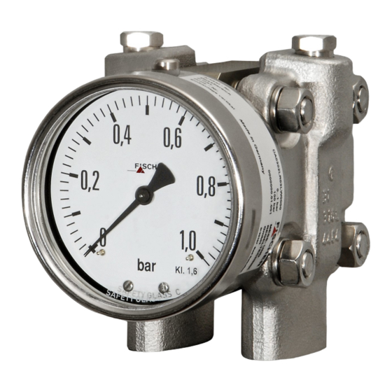
- Page 1 Operation manual DA03 GKT/HLP (ATEX) Differential pressure measuring device Pressure levels PN40/PN100/PN160 Models for use in explosive areas DA03 ... 0A DA03 ... 1B DA03 ... 1C DA03 ... 2D...
- Page 2 Great care was taken when compiling the texts and illustrations; Nevertheless, errors cannot be ruled out. The company FISCHER Mess- und Regeltechnik GmbH will not accept any legal responsibility or liability for this.
-
Page 3: Table Of Contents
FISCHER Mess- und Regeltechnik GmbH Table of Content Table of Content 1 Safety guidelines ......................4 1.1 General........................... 1.2 Personnel Qualification......................1.3 Risks due to Non-Observance of Safety Instructions ............. 1.4 Safety Instructions for the Operating Company and the Operator ......... -
Page 4: Safety Guidelines
1 | Safety guidelines FISCHER Mess- und Regeltechnik GmbH 1 Safety guidelines 1.1 General This operating manual contains basic instructions for the installation, operation and maintenance of the device that must be followed without fail. It must be read by the installer, the operator and the responsible specialist personnel be- fore installing and commissioning the device. -
Page 5: Unauthorised Modification
FISCHER Mess- und Regeltechnik GmbH Safety guidelines | 1 • evident damage to the instrument • failure of the electrical circuits • longer storage outside the approved temperature range. • considerable strain due to transport Repairs may be carried out by the manufacturer only. -
Page 6: Pictogram Explanation
1 | Safety guidelines FISCHER Mess- und Regeltechnik GmbH 1.8 Pictogram explanation DANGER Type and source of danger This indicates a direct dangerous situation that could lead to death or serious injury (highest danger level). 1. Avoid danger by observing the valid safety regulations. -
Page 7: Product And Functional Description
FISCHER Mess- und Regeltechnik GmbH Product and functional description | 2 2 Product and functional description 2.1 Delivery scope • Differential pressure measuring device DA03 • Operating Manual 2.2 Equipment versions The following illustrations depict typical combinations of the measuring cell, measured value display and contact elements. - Page 8 2 | Product and functional description FISCHER Mess- und Regeltechnik GmbH ATEX marking II 2G Ex h IIC T4 Gb II 2D Ex h IIIC T95°C Db Intrinsically safe circuit Ta = -20°C bis +60°C max. Voltage: T Medium in the unit max. 85°C max.
- Page 9 FISCHER Mess- und Regeltechnik GmbH Product and functional description | 2 2.2.5 Assembly Wall mounting Pipe mounting Panel mounting set type 1 Panel mounting set type 2 with panel mounting set with front ring Fig. 6: Assembly types The panel installation fittings can only be used in devices with a small measur- ing cell (Ø75) and a display in the NG100 bayonet ring casing.
- Page 10 2 | Product and functional description FISCHER Mess- und Regeltechnik GmbH Small measuring cell Ø75 Measurement range 0 ... 250 mbar 0 ... 400 mbar -100 ... 150 mbar -150 ... 250 mbar 0 ... 0.6 bar 0 ... 1 bar 0 ...
-
Page 11: Intended Use
FISCHER Mess- und Regeltechnik GmbH Product and functional description | 2 2.3 Intended use The DA03 serves to display differential pressures in neutral gaseous and fluid media. If used with aggressive media, the media compatibility with the materials used must be checked (see Techn. data). - Page 12 2 | Product and functional description FISCHER Mess- und Regeltechnik GmbH In the case of one-sided pressure by the measuring system above and beyond the measuring range, the over-pressure guard will be activated. The over-pres- sure causes the overloaded membrane and its collar to be pressed against the inner O-ring.
-
Page 13: Assembly
FISCHER Mess- und Regeltechnik GmbH Assembly | 3 3 Assembly 3.1 General information The device can be mounted in one of the following ways (see Assembly [} 9]): 1. Wall mounting The device is designed for installation onto flat assembly plates. The unit is equipped with a wall mounting plate for this mounting type. -
Page 14: Electrical Connections
3 | Assembly FISCHER Mess- und Regeltechnik GmbH 3.3 Electrical connections DANGER Operation in areas at risk of explosion If operated in explosive areas, the electrical data of the unit and the valid local regulations and guidelines for the installation and operation of electrical systems in explosive areas must be observed. - Page 15 FISCHER Mess- und Regeltechnik GmbH Assembly | 3 Fig. 11: HAN connector Cable screw connection M20 x 1.5 2 Sleeve housing Han 3A Socket insert Han 7D 4 Pin insert Han 7D Safety clip 6 Attachment casing Han 3D 3.3.2 Contact elements Contact elements are supplied in accordance with data sheet KE.
-
Page 16: Use In Areas At Risk Of Explosion
3 | Assembly FISCHER Mess- und Regeltechnik GmbH 3.4 Use in areas at risk of explosion 3.4.1 Differential pressure transmitter without contact element DA03 … 0A II 2G Ex h IIC T4 Gb II 2D Ex h IIIC T95°C Db Explosive areas Zone 1 and 2, and 21 and 22, risk from gases and dry dust. - Page 17 FISCHER Mess- und Regeltechnik GmbH Assembly | 3 3.4.2 Differential pressure transmitter with magnetic spring contacts DA03 … 1B II 2G Ex h IIC T4 Gb Simple electric operating equipment acc. to EN60079-11 sec: 5.7 in explosive areas Zone 1 und 2.
- Page 18 3 | Assembly FISCHER Mess- und Regeltechnik GmbH 3.4.3 Differential pressure transmitter with inductive contacts DA03 … 1C II 2G Ex h IIC T4 Gb II 2D Ex h IIIC T95°C Db Explosive areas Zone 1 and 2, and 21 and 22, risk from gases and dry dust.
- Page 19 FISCHER Mess- und Regeltechnik GmbH Assembly | 3 Intrinsically safe power circuits For use in areas at risk of explosion, instruments must be connected to certified, intrinsically safe electricity circuits. Max. voltage Max. current 25 mA Max. power 64 mW Max.
- Page 20 3 | Assembly FISCHER Mess- und Regeltechnik GmbH Intrinsically safe power circuits For use in areas at risk of explosion, instruments must be connected to certified, intrinsically safe electricity circuits. Max. voltage Max. current 160 mA Max. power 1 mW Max.
-
Page 21: Commissioning
FISCHER Mess- und Regeltechnik GmbH Commissioning | 4 4 Commissioning 4.1 General All electrical supply, operating and measuring lines, and the pressure connec- tions must have been correctly installed before commissioning. All supply lines are arranged so that there are no mechanical forces acting on the device. -
Page 22: Zero Point Correction
4 | Commissioning FISCHER Mess- und Regeltechnik GmbH 4.3 Zero point correction The differential pressure measuring units are set in the factory before delivery so that they do not usually need to be adjusted at the assembly site. If this is still necessary, proceed as follows: •... - Page 23 FISCHER Mess- und Regeltechnik GmbH Commissioning | 4 Adjustment sequence: • Press the axle inwards until the drive arm reaches behind the setting pin of the target value indicator. • Set the target value indicator to the required switch point by turning the set- ting key.
-
Page 24: Servicing
5 | Servicing FISCHER Mess- und Regeltechnik GmbH 5 Servicing 5.1 Maintenance The instrument is maintenance-free. We recommend the following regular in- spection to guarantee reliable operation and a long service life: • Check the function in combination with downstream components. -
Page 25: Technical Data
FISCHER Mess- und Regeltechnik GmbH Technical data | 6 6 Technical data 6.1 General information EXECUTION Nominal Measuring Application information pressure cell DA03 G … PN40 Ø75 Measuring ranges: 0…0.6 bar to 0…25 bar Remote seals: It is possible to attach remote seals for measuring ranges ≥ 0.6 bar. -
Page 26: Input Variables
6 | Technical data FISCHER Mess- und Regeltechnik GmbH 6.2 Input variables Measuring variable Differential pressure in gaseous and fluid aggressive media. General information Rated pressure of the measuring Max. static operating pressure system Durability One-sided over-pressure-proof up to the... -
Page 27: Operating Conditions
FISCHER Mess- und Regeltechnik GmbH Technical data | 6 6.3 Operating conditions Permissible ambient temperature -20 … +60 °C Admissible storage temperature -40 … +80 °C Admissible media temperature Max. 100 °C Type of protection: IP 65 acc. to EN 60529 6.4 Construction design... - Page 28 6 | Technical data FISCHER Mess- und Regeltechnik GmbH Assembly Wall mounting Flanged assembly plate Pipe mounting Flanged assembly plate and attachment bracket Panel mounting set Panel installation fittings for units with a small measuring type 1 cell (Ø75) and NG100 bayonet ring casing.
- Page 29 FISCHER Mess- und Regeltechnik GmbH Technical data | 6 6.4.2 Electrical connection In the case of devices with additional electronic equipment, the connection is realised using a cable socket attached to the side and/or with a Han 7D con- nector on th epower plant models. The pin assignment depends on the ordered mode and is stated in the data sheet KE or KE09.
- Page 30 6 | Technical data FISCHER Mess- und Regeltechnik GmbH 6.4.3 Dimensional drawings All dimensions in mm unless otherwise stated Small measuring system (Ø75) PN40 147.5 PN100 147.5 PN160 161.5 Wall mounting plate Flange based on DIN EN 61518 Wall mounting plate G½...
- Page 31 FISCHER Mess- und Regeltechnik GmbH Technical data | 6 Large measuring system (Ø130) 196.5 Wall mounting plate Wall mounting plate Flange based on DIN EN 61518 G½ 7/16 UNF Fig. 22: Dimensional drawing (Large measuring system Ø130) Installation of front panel type 1 (only small measuring system Ø75 and NG100 display)
- Page 32 6 | Technical data FISCHER Mess- und Regeltechnik GmbH Installation of front panel type 2 The front plate thickness must be min. 2 mm. Front ring Bayonet ring with connecting bracket NG100 A suitable steel construction must be used to ensure NG160 that the front plate can bear the weight of the device.
- Page 33 FISCHER Mess- und Regeltechnik GmbH Technical data | 6 Contact elements NG100 = 90 NG100 = 138 NG160 = 120 NG160 = 167.5 Fig. 25: Dimensional drawing contact devices Shut-off fitting Cutting ring connection G3/8 with inner spindle thread for 12 mm pipe...
-
Page 34: Order Codes
7 | Order Codes FISCHER Mess- und Regeltechnik GmbH 7 Order Codes Code no. 11 12 Type Device model: Pressure level Measuring cell PN40 Ø75 PN40 Ø130 PN100 Ø75 PN100 Ø130 PN160 Ø75 PN160 Ø130 Measuring range: Small measuring system [2.3]... - Page 35 FISCHER Mess- und Regeltechnik GmbH Order Codes | 7 Large measuring system [2.3] Measurement range Device model Ø130 0 … 40 mbar ● ● ● 0 … 60 mbar ● ● ● 0 … 100 mbar ● ● ● 0 … 160 mbar ●...
- Page 36 7 | Order Codes FISCHER Mess- und Regeltechnik GmbH Fluid filling: Without fluid filling Glycerine Paraffin oil Silicon oil Special functions: [10] Without special function Adjustable marker needle Resettable drag needle Contacts/transmitters/ATEX: [11.12] ATEX model Non-electrical unit II 2G Ex h IIC T4 Gb (without switch contacts) II 2D Ex h IIIC T95°C Db...
-
Page 37: Accessories
FISCHER Mess- und Regeltechnik GmbH Order Codes | 7 7.1 Accessories Order no. Planned measures Material DZ3600SV2700 Triple valve block DN5 PN420 1.4571 • Flange connection acc. to DIN EN 61518 • Cutting ring screw connections 12 mm pipe • Including assembly set Order no. -
Page 38: Eu Declaration Of Conformity
8 | EU Declaration of Conformity FISCHER Mess- und Regeltechnik GmbH 8 EU Declaration of Conformity Fig. 27: CE_DE_DA03...0A_Page_01 38/56 BA_EN_DA03_GKT_HLP_ATEX... - Page 39 FISCHER Mess- und Regeltechnik GmbH EU Declaration of Conformity | 8 Fig. 28: CE_DE_DA03...0A_Page_02 BA_EN_DA03_GKT_HLP_ATEX 39/56...
- Page 40 8 | EU Declaration of Conformity FISCHER Mess- und Regeltechnik GmbH Fig. 29: CE_DE_DA03...1B_Page_01 40/56 BA_EN_DA03_GKT_HLP_ATEX...
- Page 41 FISCHER Mess- und Regeltechnik GmbH EU Declaration of Conformity | 8 Fig. 30: CE_DE_DA03...1B_Page_02 BA_EN_DA03_GKT_HLP_ATEX 41/56...
- Page 42 8 | EU Declaration of Conformity FISCHER Mess- und Regeltechnik GmbH Fig. 31: CE_DE_DA03...1C_Page_01 42/56 BA_EN_DA03_GKT_HLP_ATEX...
- Page 43 FISCHER Mess- und Regeltechnik GmbH EU Declaration of Conformity | 8 Fig. 32: CE_DE_DA03...1C_Page_02 BA_EN_DA03_GKT_HLP_ATEX 43/56...
- Page 44 8 | EU Declaration of Conformity FISCHER Mess- und Regeltechnik GmbH Fig. 33: CE_DE_DA03...2D_Page_01 44/56 BA_EN_DA03_GKT_HLP_ATEX...
- Page 45 FISCHER Mess- und Regeltechnik GmbH EU Declaration of Conformity | 8 Fig. 34: CE_DE_DA03...2D_Page_02 BA_EN_DA03_GKT_HLP_ATEX 45/56...
-
Page 46: Ukca Declarations Of Conformity
9 | UKCA Declarations of Conformity FISCHER Mess- und Regeltechnik GmbH 9 UKCA Declarations of Conformity Fig. 35: UKCA_EN_DA03_0A 46/56 BA_EN_DA03_GKT_HLP_ATEX... - Page 47 FISCHER Mess- und Regeltechnik GmbH UKCA Declarations of Conformity | 9 Fig. 36: UKCA_EN_DA03_1B_Page_1 BA_EN_DA03_GKT_HLP_ATEX 47/56...
- Page 48 9 | UKCA Declarations of Conformity FISCHER Mess- und Regeltechnik GmbH Fig. 37: UKCA_EN_DA03_1B_Page_2 48/56 BA_EN_DA03_GKT_HLP_ATEX...
- Page 49 FISCHER Mess- und Regeltechnik GmbH UKCA Declarations of Conformity | 9 Fig. 38: UKCA_EN_DA03_1C_Page_1 BA_EN_DA03_GKT_HLP_ATEX 49/56...
- Page 50 9 | UKCA Declarations of Conformity FISCHER Mess- und Regeltechnik GmbH Fig. 39: UKCA_EN_DA03_1C_Page_2 50/56 BA_EN_DA03_GKT_HLP_ATEX...
- Page 51 FISCHER Mess- und Regeltechnik GmbH UKCA Declarations of Conformity | 9 Fig. 40: UKCA_EN_DA03_1C_Page_2 BA_EN_DA03_GKT_HLP_ATEX 51/56...
- Page 52 9 | UKCA Declarations of Conformity FISCHER Mess- und Regeltechnik GmbH Fig. 41: UKCA_EN_DA03_2D_Page_2 52/56 BA_EN_DA03_GKT_HLP_ATEX...
-
Page 53: 10Eac Declaration
FISCHER Mess- und Regeltechnik GmbH EAC Declaration | 10 10 EAC Declaration Fig. 42: ЕАЭС N RU Д-DЕ.АЛ16.В.77754 BA_EN_DA03_GKT_HLP_ATEX 53/56... - Page 54 FISCHER Mess- und Regeltechnik GmbH 54/56 BA_EN_DA03_GKT_HLP_ATEX...
- Page 55 FISCHER Mess- und Regeltechnik GmbH BA_EN_DA03_GKT_HLP_ATEX 55/56...
- Page 56 Mess- und Regeltechnik GmbH Bielefelder Str. 37a D-32107 Bad Salzuflen Tel. +49 5222 974-0 Fax +49 5222 7170 www.fischermesstechnik.de info@fischermesstechnik.de Technische Änderungen vorbehalten. Subject to technical changes. Sous réserve de modifications techniques.
Need help?
Do you have a question about the DA03 GKT/HLP and is the answer not in the manual?
Questions and answers