Primes BeamMonitor BM+ 60 Original Instructions Manual
Laserdiagnosticssoftware lds
Hide thumbs
Also See for BeamMonitor BM+ 60:
- Operating manual (84 pages) ,
- Operating manual (38 pages)

Related Manuals for Primes BeamMonitor BM+ 60


Summary of Contents for Primes BeamMonitor BM+ 60
- Page 1 Original Instructions BeamMonitor BM+ 100S BeamMonitor BM+ BM+ 60, BM+ 100S LaserDiagnosticsSoftware LDS Revision 02 EN - 02/2022...
- Page 3 BeamMonitor BM+ IMPORTANT! READ CAREFULLY BEFORE USE. KEEP FOR FUTURE USE. Revision 02 EN - 02/2022...
-
Page 4: Table Of Contents
Mount the device ......................15 Deinstallation of the device ......................18 Connections Overview of the connections ....................18 8.1.1 Connections of the BeamMonitor BM+ 60 ..............18 8.1.2 Connections of the BeamMonitor BM+ 100S ..............18 Power supply (Power In) ......................19 Ethernet ..........................20 PRIMES bus RS485 ........................20 Connection of the BeamMonitor BM+ and PowerMonitor PM 48/100 to the PC .....21... - Page 5 11.2 Cleaning the device surfaces ....................57 Measures for the product disposal Declaration of conformity Technical data Dimensions 15.1 BeamMonitor BM+ 60 ......................62 15.2 BeamMonitor BM+ 100S ......................63 Appendix 16.1 GNU GPL license notice ......................64 16.2 Variety of detectors .........................64 16.3 Replace the detector .......................65 16.3.1 Remove cover ......................65...
- Page 6 • Beam quality factor M² PRIMES is responsible for both the development, production, and calibration of the measuring devices. This guarantees optimum quality, excellent service, and a short reaction time, providing the basis for us to meet all of our customers’ requirements quickly and reliably.
-
Page 7: Basic Safety Notes
Every person who is responsible for the installation, start-up or operation of the device must have read and understood the operating manual and, in particular, the safety instructions. If you still have questions after reading this operating manual, please contact PRIMES or your supplier for your own safety. -
Page 8: Symbols And Conventions
BeamMonitor BM+ Employing qualified personnel The device may only be operated by qualified personnel. The qualified personnel must have been instructed in the installation and operation of the device and must have a basic understanding of working with high- power lasers, beam guiding systems and focusing units. Conversions and modifications The device may not be modified in terms of design or safety without the explicit consent of the manufacturer. -
Page 9: About This Operating Manual
BeamMonitor BM+ General warning sign Observe beam path Further symbols and conventions in this operating manual Here you can find useful information and helpful tips. Indicates a simple instruction. If several such instructions appear one below the other, then the order of their execution is irrel- evant or they are alternative procedures. -
Page 10: Device Description
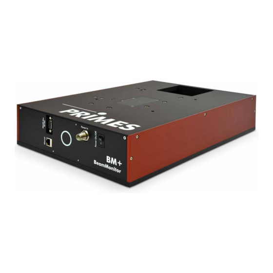
BeamMonitor BM+ Device description Device type overview There are two types of the BeamMonitor BM+. BeamMonitor BM+ 60 BeamMonitor BM+ 100S Fig. 4.1: Device types BM+ 60 and BM+ 100S Functional description The BeamMonitor BM+ is an opto-mechanically scanning measuring system that scans the laser beam with a special measuring tip. -
Page 11: Optical Displays
BeamMonitor BM+ Optical displays The status display consists of a light ring that indicates different states of the BeamMonitor BM+ with differ- ent colors and static or rotating lights. Color Lighting state Meaning White The entire ring illuminates The supply voltage is connected Yellow Rotating light The measuring tip rotates. -
Page 12: Observe Beam Path
Beam path using the BM+ 60 as an example Scope of delivery and accessories The following parts are included in the scope of delivery of the BeamMonitor BM+: • BeamMonitor BM+ • PRIMES power supply • Power cable • Patch cable Cat.5e, 5 m, Cross-Over •... -
Page 13: Quick Overview Installation
Establish connections Chapter 8 on page 18 • Power supply Power In • Ethernet • PRIMES-Bus (RS485) • Parallel operation of the BeamMonitor BM+ for example with the laser power meter PowerMonitor PM 48/100 Measure Chapter 9 on page 22 • Observe warning messages •... -
Page 14: Mounting
When the BeamMonitor BM+ is being operated, the irradiation must be fully absorbed behind the measurement zone. Fire bricks or other partly-absorbing surfaces are not suitable. X Use an adequate absorber. Dependent on the application, PRIMES offers suitable laser power me- ters, such as the PowerMonitor PM 48/100. -
Page 15: Align The Device
BeamMonitor BM+ 7.2.3 Align the device For the BeamMonitor BM+, a perpendicular beam incidence with respect to the x-y plane must be ensured. The laser beam should hit the inlet aperture in the center. DANGER Serious eye or skin injury due to laser radiation If the ratio of the laser beam diameter to the inlet aperture is too large, increased scattered or di- rected reflection of the laser beam (laser class 4) will occur during measuring operation. - Page 16 BeamMonitor BM+ Mount the BeamMonitor BM+ 60 Beam Ø 60 Beam Fig. 7.2: Threaded holes on the BeamMonitor BM+ 60 Revision 02 EN - 02/2022...
- Page 17 BeamMonitor BM+ Mount the BeamMonitor BM+ 100S 4x M6 Fig. 7.3: Threaded holes on the BeamMonitor BM+ 100S Revision 02 EN - 02/2022...
-
Page 18: Deinstallation Of The Device
5. Disconnect the cables and remove the device from the laser system. Connections Please only use the PRIMES power supply unit and the provided connection cables. Please establish all electrical connections and switch on the device before starting the LaserDiagnosticsSoft- ware LDS. -
Page 19: Power Supply (Power In)
Connection of the power supply using the BM+ 100S as an example Harting M12-P-PCB-THR-2PC-5P-LCOD-M-STR Function +24 V Not assigned Not assigned FE (functional earth) Tab. 8.1: Pin assignment of the connection socket for the PRIMES power supply Revision 02 EN - 02/2022... -
Page 20: Ethernet
BM+. Pin assignment D-sub socket, 9-pin (view of plug-in side) Function RS485 (+) +24 V Not assigned Not assigned RS485 (–) +24 V Not assigned Tab. 8.2: Pin assignment of the D-Sub socket, PRIMES bus Revision 02 EN - 02/2022... -
Page 21: Connection Of The Beammonitor Bm+ And Powermonitor Pm 48/100 To The Pc
Connection of the BeamMonitor BM+ and PowerMonitor PM 48/100 to the PC For sufficient absorption of the radiation behind the measurement zone, you can use the PRIMES laser power meter PM 48/100. The water-cooled PM 48/100 will measure the current laser power and provide ad- ditional information on the flow rate and temperature of the cooling water. -
Page 22: Measuring With The Laserdiagnosticssoftware Lds
When the BeamMonitor BM+ is being operated, the irradiation must be fully absorbed behind the measurement zone. Fire bricks or other partly-absorbing surfaces are not suitable. X Use an adequate absorber. Dependent on the application, PRIMES offers suitable laser power me- ters, such as the PowerMonitor PM 48/100. - Page 23 BeamMonitor BM+ CAUTION Risk of injury caused by rotating parts The measuring tip of the BeamMonitor BM+ rotates at high speed during the measuring operation. Even after the measurement or switching off the device, the measuring tip will continue to rotate for a certain amount of time.
-
Page 24: Connecting / Disconnecting The Device With The Laserdiagnosticssoftware Lds
The PRIMES device obtains an IP address from the network via the Ethernet connection. The PC used must be in the same IP address range as the PRIMES device. The DHCP option is deactivated by default (see chapter 9.2.3 on page 26). -
Page 25: If The Device Does Not Appear In The Connections Window
X In Windows > Control panel > Net- work and Sharing Center, assign an IP address to your PC that is in the same address range as the PRIMES device (e.g. 192.168.116.xyz). The IP address of your PRIMES device can be found on the identifica- tion plate. -
Page 26: Change The Network Address Of A Connected Device
BeamMonitor BM+ 9.2.3 Change the network address of a connected device For communication in a network, a Static IP address is stored for the device in the LDS and the function Use DHCP is activated. When establishing a connection, the device will first wait to be assigned a suitable IP address via DHCP. -
Page 27: General Information About Working With The Lds
BeamMonitor BM+ General information about working with the LDS This chapter contains general information about the LDS. Read this general information before turning to the following chapters on the various measurement modes. 9.3.1 Open „Device control“ menu Click on the Devices tab. Select the device and click on the device function Scanner below the device name. -
Page 28: Enter Parameters And Activate
BeamMonitor BM+ After selecting the measuring mode, the corresponding toolbench is opened. If the toolbench has been closed, re-open it by clicking the Open measurement toolbench button. 9.3.3 Enter parameters and activate Be aware that when configuring settings in one mode, some options are also applied in other modes as well. For example, if you enter a parameter in the Single planes mode, it will be automatically applied to all other modes that use this same parameter. -
Page 29: Move Axes
BeamMonitor BM+ 9.3.4 Move axes Within all measuring modes, the mea- suring tip can be moved to a defined y-position. Click on the Advanced tab. Click on the arrow to open the drop- down list. Use one of the following options: X Enter a value in the parameter field and confirm the entry with the Enter key. -
Page 30: Saving Options
BeamMonitor BM+ 9.3.5 Saving options The LDS offers (up to) three different options for saving. They differ by the storage location and the selection of the data to be saved. When saving / loading a configuration, note that the command is called in a certain measurement mode, but the saved / loaded data set also includes the settings of the other measurement modes. -
Page 31: Considering The Messages In The Laserdiagnosticssoftware Lds During Measurement
BeamMonitor BM+ 9.3.6 Considering the messages in the LaserDiagnosticsSoftware LDS during measurement If problems occur during a measurement, the LaserDiagnosticsSoftware LDS displays them in different cat- egories and different colors. Notes Notes provide assistance in interpreting the measurement results and are dis- played in a blue window. -
Page 32: Single Planes
BeamMonitor BM+ Single planes In Single planes measuring mode, single planes are measured at selected z-positions. Measurement win- dow size and the gain can be set automatically or determined freely. You can also have the software search the laser beam automatically in the entire measurement range. To measure a manual caustic (see chapter 9.4.6 „Manual caustic measure“... - Page 33 BeamMonitor BM+ Option Explanation z-Increment in mm This option automatically defines the position of the next measurement on the z-axis (see chapter chapter 9.4.6 „Manual caustic measure“ on page 39). Since the BeamMonitor BM+ does not have a z-axis, the laser or the device must be moved according to the entered value.
- Page 34 BeamMonitor BM+ Option Explanation Parameter settings All settings in the Device control menu can be individually saved for each device. The saving location is the local installation of the LDS. These and other options for saving / loading configurations are de- scribed in chapter 9.3.5 „Saving options“...
-
Page 35: Advanced Settings
BeamMonitor BM+ 9.4.2 Advanced settings Click on the Advanced tab. Edit the options according to the ex- planations in Tab. 9.2 on page 35. Option Explanation Save device settings All options marked with an asterisk in the Device control menu can be saved in the EEPROM of the device. - Page 36 BeamMonitor BM+ Option Explanation Move axes With this option you can move to a defined y-position. Use one of the following options: X Enter a value in the input field. X Use the slider below the input field. This option is described in chapter 9.3.4 „Move axes“ on page 29. Tab.
-
Page 37: Search Laser Beam Automatically With The Find Beam Function
BeamMonitor BM+ 9.4.3 Search laser beam automatically with the find beam function Follow the warning messages in chapter 9.1 on page 22. Switch on the laser. Click on the Settings tab. Click on the Find beam button. The laser beam is automatically searched for in the entire measuring range. -
Page 38: Adjust The Size And Position Of The Measurement Window Manually
BeamMonitor BM+ 9.4.4 Adjust the size and position of the measurement window manually Click on the Settings tab. Make sure that the autom. Measure- ment window option is not enabled. Otherwise, the manual setting may be overwritten when starting a measure- ment. -
Page 39: Start Measurement
BeamMonitor BM+ 9.4.5 Start measurement Follow the warning messages in chapter 9.1 on page 22. Click the Start button. The measurement begins. Optional: X Click the Stop button to abort the measurement. X Click the Stop Rotation button to stop the rotation of the measuring tip. During the measurement, the prog- ress is shown in the following indica- tors:... - Page 40 BeamMonitor BM+ Single measurements using z-incre- ment spacing: Click on the Settings tab. Enter the spacing for the further measurements in the z-Increment in mm field. Start the measurement according to chapter 9.4.5 on page 39 and wait until the measurement is completed. ...
-
Page 41: Display Of The Measurement Results
BeamMonitor BM+ 9.4.7 Display of the measurement results The measurement results are displayed after the finished measurement in the opened tools (see below). We recommend checking the quality of the results after a measurement. Depending on the results, it may seem necessary to repeat the measurement with improved measurement setup or changed parameters. -
Page 42: Monitor
BeamMonitor BM+ Monitor In Monitor measuring mode, measuring planes can be continuously observed in a false-color image. The laser beam can be automatically searched by the software in the entire measurement range. After a successful search the measurement can be run as long as desired. During the measurement, data is continuously being read out and displayed in the graphic view. - Page 43 BeamMonitor BM+ Option Explanation Window size in mm If the autom. Measurement window option is disabled, the size of the measurement window can be set manually. Use one of the following options: X Enter the length and width in the corresponding fields. X Position the mouse pointer anywhere within the measurement range and drag while holding down the left mouse button.
-
Page 44: Advanced Settings
BeamMonitor BM+ 9.5.2 Advanced settings Click on the Advanced tab. Edit the options according to the ex- planations in Tab. 9.4 on page 44. Option Explanation Save device settings All options marked with an asterisk in the Device control menu can be saved in the EEPROM of the device. -
Page 45: Search Laser Beam Automatically With The Find Beam Function
BeamMonitor BM+ 9.5.3 Search laser beam automatically with the find beam function Follow the warning messages in chapter 9.1 on page 22. Switch on the laser. Click on the Settings tab. Click on the Find beam button. The laser beam is automatically searched for in the entire measuring range. -
Page 46: Adjust The Size And Position Of The Measurement Window Manually
BeamMonitor BM+ 9.5.4 Adjust the size and position of the measurement window manually Click on the Settings tab. Use one of the following options to adjust the size of the measurement window: X Enter the length and width in the cor- responding fields. -
Page 47: Start Measurement
BeamMonitor BM+ 9.5.5 Start measurement DANGER Serious eye or skin injury due to laser radiation If you use a continuous plane measurement in the Monitor measurement mode to align the de- vice, note the following: X Preferably align the device with a pilot laser where no dangerous reflections can occur. X If the device is aligned with a laser class 4, dangerous reflections may occur. -
Page 48: Display Of The Measurement Results
BeamMonitor BM+ 9.5.6 Display of the measurement results During the measurement, data is continuously being read out and displayed in the graphic view. Measure- ment data is not saved in the project tree of the Projects tab. Revision 02 EN - 02/2022... -
Page 49: Linescan
BeamMonitor BM+ Linescan In measuring mode Linescan, the laser beam is measured at a defined position on the y-axis over a specific period of time. The line width, line center and position on the y-axis are freely adjustable. The measuring tip of the BeamMonitor BM+ is moved to a fixed y-position. At this position, it measures the power density on a single measuring path with every rotation of the measurement tip. - Page 50 BeamMonitor BM+ Option Explanation Line width in mm Use one of the following options to adjust the line width (length) and position: X Enter the width (length) of the line. X Position the mouse pointer at any point within the measurement area and drag while holding down the left mouse button.
-
Page 51: Advanced Settings
BeamMonitor BM+ 9.6.2 Advanced settings Click on the Advanced tab. Edit the options according to the ex- planations in Tab. 9.6 on page 51. Option Explanation Save device settings All options marked with an asterisk in the Device control menu can be saved in the EEPROM of the device. -
Page 52: Search Laser Beam Automatically With The Find Beam Function
BeamMonitor BM+ 9.6.3 Search laser beam automatically with the find beam function Follow the warning messages in chapter 9.1 on page 22. Switch on the laser. Click on the Settings tab. Click on the Find beam button. The laser beam is automatically searched for in the entire measuring range. -
Page 53: Adjust The Width (Length) And Position Of The Measuring Line Manually
BeamMonitor BM+ 9.6.4 Adjust the width (length) and position of the measuring line manually Click on the Settings tab. Use one of the following options to adjust the line width (length): X Enter the width (length) of the line. X Position the mouse pointer at any point within the measurement area and drag while holding down the left mouse button. -
Page 54: Start Measurement
BeamMonitor BM+ 9.6.5 Start measurement Follow the warning messages in chapter 9.1 on page 22. Click the Start button. The measurement begins. Optional: X Click the Stop button to abort the measurement. X Click the Stop Rotation button to stop the rotation of the measuring tip. During the measurement, the prog- ress is shown in the following indica- tors:... -
Page 55: Display Of The Measurement Results
BeamMonitor BM+ 9.6.6 Display of the measurement results The measurement results are displayed during and after the finished measurement in the opened tool (see below). We recommend checking the quality of the results after a measurement. Depending on the results, it may seem necessary to repeat the measurement with improved measurement setup or changed param- eters. -
Page 56: Troubleshooting
PRIMES device (e.g. the PC. 192.168.116.xyz). The IP address of your PRIMES device can be found on the identification plate. The connection may be blocked Enable the UDP port 20034 according to chapter 9.2.2 by the firewall. -
Page 57: Maintenance And Service
PRIMES gives you the opportunity to return your PRIMES measuring device for free disposal within the scope of the Waste of Electrical and Electronic Equipment (WEEE Directive). This service does not include shipping costs. You can send PRIMES measuring devices to be disposed of within the EU to our address: PRIMES GmbH Max-Planck-Str. -
Page 58: Declaration Of Conformity
BeamMonitor BM+ Declaration of conformity Revision 02 EN - 02/2022... - Page 59 BeamMonitor BM+ Revision 02 EN - 02/2022...
-
Page 60: Technical Data
BeamMonitor BM+ Technical data Measurement parameters BM+ 60 BM+ 100S Power range 50 – 25 000 W Wavelength range 450 – 1090 nm or 10 600 nm Beam diameter 5 – 42 mm (NIR) 10 – 70 mm 10 – 42 mm (CO Min. power density (CO devices only) 0.1 kW/cm²... - Page 61 BeamMonitor BM+ Environmental conditions Operating temperature range 10 – 40 °C Storage temperature range 5 – 50 °C Reference temperature 22 °C Permissible relative humidity (non-condensing) 10 – 80 % Revision 02 EN - 02/2022...
-
Page 62: Dimensions
BeamMonitor BM+ Dimensions 15.1 BeamMonitor BM+ 60 Ø 60 Laser beam Laserstrahl Revision 02 EN - 02/2022... -
Page 63: Beammonitor Bm+ 100S
BeamMonitor BM+ 15.2 BeamMonitor BM+ 100S 4x M6 Laser beam Beam Revision 02 EN - 02/2022... -
Page 64: Appendix
BeamMonitor BM+ Appendix 16.1 GNU GPL license notice The software of this product contains software code that is licensed subject to the GNU General Public License (GPL) Version 2 or later. The license terms of the GNU GPL Version 2 or later are available on the following websites: •... -
Page 65: Replace The Detector
BeamMonitor BM+ 16.3 Replace the detector Generally, the BeamMonitor BM+ is equipped with a DBIG-PS+ or DBC+ detector, depending on the wave- length. Detectors with different sensitivity or different time behavior can be used for special applications (see Tab. 16.1 on page 64). 16.3.1 Remove cover 1. - Page 66 BeamMonitor BM+ 1. Remove the plastic screws (D) from the detector (see Fig. 16.3 on page 66). Fig. 16.3: Remove the plastic screws from the detector 2. Carefully remove the detector from the position. Please do not pull the cables. 3. First loosen the golden angle plug (A), then the black plug (B) (see Fig. 16.4 on page 66). Touch here Touch here Do not...
-
Page 67: Assemble The Detector
BeamMonitor BM+ 16.3.3 Assemble the detector Only use isolating plastic screws to fasten the detector to prevent any electric noise signals from being interspersed. Do not forget the foam rubber spacer during installation, otherwise the rota- tional disc could be mechanically blocked by the screws. The foam rubber spacer also ensures mechanical decoupling of the detector. - Page 68 BeamMonitor BM+ Revision 02 EN - 02/2022...
Need help?
Do you have a question about the BeamMonitor BM+ 60 and is the answer not in the manual?
Questions and answers