
Related Manuals for Primes BeamMonitor BM+ Series


Summary of Contents for Primes BeamMonitor BM+ Series
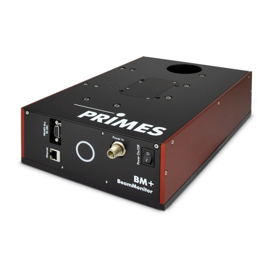
- Page 1 Operating Manual Translation of the original instructions BeamMonitor BM+ BM+ 60, BM+ 100 LaserDiagnosticsSoftware LDS Revision 02/2019 EN...
- Page 3 BeamMonitor BM+ IMPORTANT! READ CAREFULLY BEFORE USE. KEEP FOR FUTURE USE. Revision 02/2019 EN...
-
Page 4: Table Of Contents
Connections ..........................18 Pin assignment ........................19 8.2.1 Power supply ......................19 8.2.2 PRIMES bus RS485 ....................19 Connection to the PC and establishing the power supply ............20 Connection of the BeamMonitor BM+ and PowerMonitor PM 48/100 to the PC .....21 Status display Measuring 10.1 Safety instructions ........................23 10.2 Connect the BeamMonitor BM+ with the LaserDiagnosticsSoftware LDS........24... - Page 5 BeamMonitor BM+ Technical data Dimensions 16.1 BeamMonitor BM+ 60 ......................32 16.2 BeamMonitor BM+ 100 ......................33 Appendix 17.1 System control (option) ......................34 17.2 Variety of detectors .........................34 17.3 Replace the detector .......................35 17.3.1 Remove cover ......................35 17.3.2 Disassemble the detector ..................35 17.3.3 Assemble the detector ....................37 17.3.4...
- Page 6 • Beam quality factor M² PRIMES is responsible for both the development, production, and calibration of the measuring devices. This guarantees optimum quality, excellent service, and a short reaction time, providing the basis for us to meet all of our customers’ requirements quickly and reliably.
-
Page 7: Basic Safety Instructions
BeamMonitor BM+ Basic safety instructions Intended Use The BeamMonitor BM+ has been designed exclusively for measurements carried out in or near the optical path of high-power lasers. Please observe and adhere to the specifications and limit values given in chap- ter 15, „Technical data“, on page 31. - Page 8 BeamMonitor BM+ Employing qualified personnel The device may only be operated by qualified personnel. The qualified personnel must have been instructed in the installation and operation of the device and must have a basic understanding of working with high- power lasers, beam guiding systems and focusing units. Conversions and modifications The device must not be modified, neither constructionally nor safety-related, without our explicit permission.
-
Page 9: Symbol Explanations
BeamMonitor BM+ Symbol explanations The following symbols and signal words indicate possible residual risks: DANGER Means that death or serious physical injuries will occur if necessary safety precautions are not taken. WARNING Means that death or serious physical injuries may occur if necessary safety precautions are not taken. -
Page 10: About This Operating Manual
When the BeamMonitor BM+ is being operated, the irradiation must be fully absorbed be- hind the measurement zone. Fire bricks or other partly-absorbing surfaces are not suitable. X Use an adequate absorber. Dependent on the application, PRIMES offers suitable absorbers, such as the PowerMonitor PM 48/100. -
Page 11: Introduction
BeamMonitor BM+ Introduction System description The BeamMonitor BM+ is an opto-mechanical scanning measurement system for analyzing continuous irra- diation. The device measures the power density distribution of the raw beam. The LaserDiagnosticsSoftware LDS uses this to calculate the beam position, beam dimensions, beam symmetry, and power density distri- bution. -
Page 12: Short Overview Installation
BeamMonitor BM+ Short overview installation Installing the LaserDiagnosticsSoftware LDS on the computer See separate Operating Manual of the LaserDiagnosticsSoftware • Software is part of the scope of delivery Taking safety precautions Chapter 1 on page 7 Prepare Installation Chapter 7 on page 13 •... -
Page 13: Transport
X Handle the device carefully when transporting or installing it. X To avoid contamination, cover the apertures with the provided lid or optical tape. X Only transport the device in the original PRIMES transport box. Installation Safety instructions... -
Page 14: Preparation
When the BeamMonitor BM+ is being operated, the irradiation must be fully absorbed be- hind the measurement zone. Fire bricks or other partly-absorbing surfaces are not suitable. X Use an adequate absorber. Dependent on the application, PRIMES offers suitable absorbers, such as the PowerMonitor PM 48/100. -
Page 15: Align The Beammonitor Bm
BeamMonitor BM+ Align the BeamMonitor BM+ For the BeamMonitor BM+, the beam must enter vertically to the x-y-plane. The laser beam must hit the inlet aperture in the middle. DANGER Serious eye or skin injury due to laser radiation If the ratio of the laser beam diameter to the aperture diameter is too large, increased scat- tered or directed reflection of the laser beam (laser class 4) will occur during measuring operation. -
Page 16: Install The Beammonitor Bm+ 60
BeamMonitor BM+ 7.5.1 Install the BeamMonitor BM+ 60 Fig. 7.3: Mounting holes on the BeamMonitor BM+ 60 Beam Revision 02/2019 EN... -
Page 17: Install The Beammonitor Bm+ 100
BeamMonitor BM+ 7.5.2 Install the BeamMonitor BM+ 100 Fig. 7.4: Mounting holes on the BeamMonitor BM+ 100 Beam Revision 02/2019 EN... -
Page 18: Electrical Connections
Another device, such as a PowerMonitor PM 48/100, can be connected to the BeamMonitor BM+ via the RS485 interface (PRIMES bus). The signal from the PowerMonitor PM 48/100 is transmitted through the BeamMonitor BM+ to the PC via the Ethernet interface. The additional measuring device is powered by the power supply of the BeamMonitor BM+. -
Page 19: Pin Assignment
Connection socket for the power supply 8.2.2 PRIMES bus RS485 Pin arrangement D-sub socket, 9-pin (view of plug-in side) Function RS485 (+) +24 V Not assigned Not assigned RS485 (–) +24 V Not assigned Tab. 8.2: D-sub socket, PRIMES bus Revision 02/2019 EN... -
Page 20: Connection To The Pc And Establishing The Power Supply
BeamMonitor BM+ = 1.8 m = 2.0 m Crossover cable Patch cable PRIMES power supply Ethernet Ethernet Fig. 8.2: Connection of BeamMonitor BM+ using the example of the BM+ 100 Connect the BeamMonitor BM+ to the PC via a crossover cable or to the network via a patch cable. -
Page 21: Connection Of The Beammonitor Bm+ And Powermonitor Pm 48/100 To The Pc
Connection of the BeamMonitor BM+ and PowerMonitor PM 48/100 to the PC For full absorption of the radiation behind the measurement zone, you can use the PRIMES PowerMonitor PM 48/100. The water-cooled PowerMonitor PM 48/100 will show you the laser power, water flow rate, and water temperature. -
Page 22: Status Display
BeamMonitor BM+ Status display The status display consists of a light ring that indicates different states of the BeamMonitor BM+ with differ- ent colors and static or rotating lights. Color Lighting state Meaning White The entire ring illuminates The supply voltage is connected Yellow Rotating light The measuring tip rotates. -
Page 23: Measuring
When the BeamMonitor BM+ is being operated, the irradiation must be fully absorbed be- hind the measurement zone. Fire bricks or other partly-absorbing surfaces are not suitable. X Use an adequate absorber. Dependent on the application, PRIMES offers suitable absorbers, such as the PowerMonitor PM 48/100. -
Page 24: Connect The Beammonitor Bm+ With The Laserdiagnosticssoftware Lds
BeamMonitor BM+ 10.2 Connect the BeamMonitor BM+ with the LaserDiagnosticsSoftware LDS 10.2.1 Connect device Switch on the BeamMonitor BM+. The operating mode is shown in the status display (see chapter 9 on page 22). Start the LaserDiagnosticsSoftware LDS. Click on the Devices tab. Click on the + Connect to device button under the tab. -
Page 25: Performing A Single Planes Measurement
BeamMonitor BM+ 10.3 Performing a single planes measurement This chapter aims to provide some basic information as you get to know the BeamMonitor BM+, discussing the example of a measurement with the LaserDiagnosticsSoftware LDS. For a detailed description of the software installation, file management and evaluation of the measured data, please refer to the separate operating manual LaserDiagnosticsSoftware LDS. -
Page 26: Performing A Manual Or Automatic Beam Search (Device Control > Settings)
BeamMonitor BM+ 10.3.2 Performing a manual or automatic beam search (Device control > Settings) Manual beam search Click on the Settings tab. Start the measurement according to chapter 10.3.4 on page 28. • The beam is displayed in the mea- surement window. -
Page 27: Configuring Advanced Settings (Device Control > Advanced)
BeamMonitor BM+ 10.3.3 Configuring advanced settings (Device control > Advanced) Click on the Advanced tab. Resolution of the measurement window Enter the number of Pixel in x/y for the measurement. Wave length Select the Calibrated wavelength in nm of your BeamMonitor BM+. Enter the Used wavelength in nm of the laser. -
Page 28: Starting Measurement
BeamMonitor BM+ 10.3.4 Starting measurement Follow the safety instructions in chap- ter chapter 10.1 on page 23. Turn on the laser. Click on the Start button. The progress of the measurement is shown in the displays Measuring plane and Measurement completed: Measuring plane During the display, the plane or, depend- ing on the setting, several planes are... -
Page 29: Troubleshooting
PRIMES is registered in the German Used Appliance Register (Elektro-Altgeräte-Register (EAR)) as a manu- facturer with the number WEEE reg. no. DE65549202. Within the EU, you are welcome to send your PRIMES measuring devices to the following address to dis- pose of them free of charge: PRIMES GmbH Max-Planck-Str. -
Page 30: Declaration Of Conformity
BeamMonitor BM+ Declaration of conformity Revision 02/2019 EN... -
Page 31: Technical Data
BeamMonitor BM+ Technical data Measurement parameters BM+ 60 BM+ 100 Power range 50 – 25 000 W Wavelength range 1 030 – 1 090 nm oder 10 600 nm Beam diameter 10 – 42 mm 10 – 70 mm Max. power density -Laser (10 600 nm) 10 kW/cm² Nd:YAG-Laser (1 030 – 1 090 nm) 10 kW/cm²... -
Page 32: Dimensions
BeamMonitor BM+ Dimensions 16.1 BeamMonitor BM+ 60 Ø 60 Laser beam Beam All dimensions in mm (general tolerance ISO 2768-v) Revision 02/2019 EN... -
Page 33: Beammonitor Bm+ 100
BeamMonitor BM+ 16.2 BeamMonitor BM+ 100 Ø 100 4x M6 Laser beam Beam Beam All dimensions in mm (general tolerance ISO 2768-v) Revision 02/2019 EN... -
Page 34: Appendix
BeamMonitor BM+ Appendix 17.1 System control (option) An optional connection to the system control is available. Please contact your PRIMES sales partner with any questions. 17.2 Variety of detectors Different detectors are used, depending on the application (see Tab. 17.1 on page 34). -
Page 35: Replace The Detector
BeamMonitor BM+ 17.3 Replace the detector Generally, the BeamMonitor BM+ is equipped with a DBIG-PS+ or DBC+ detector. Detectors with different sensitivity or different time behavior can be used for special applications (siehe Tab. 17.1 on page 34). 17.3.1 Remove cover 1. - Page 36 BeamMonitor BM+ 1. Remove the plastic screws (D) from the detector (see Fig. 17.3 on page 36). Fig. 17.3: Remove the plastic screws from the detector 2. Carefully remove the detector from the position. X Please do not pull the cables. 3.
-
Page 37: Assemble The Detector
BeamMonitor BM+ 17.3.3 Assemble the detector Only use isolating plastic screws to fasten the detector to prevent any electric noise signals from being interspersed. Do not forget the foam rubber spacer during installation, otherwise the rota- tional disc could be mechanically blocked by the screws. The foam rubber spacer also ensures mechanical decoupling of the detector. - Page 38 BeamMonitor BM+ Revision 02/2019 EN...
Need help?
Do you have a question about the BeamMonitor BM+ Series and is the answer not in the manual?
Questions and answers