
Subscribe to Our Youtube Channel
Related Manuals for SEW-Eurodrive MOVIDRIVE modular


Summary of Contents for SEW-Eurodrive MOVIDRIVE modular
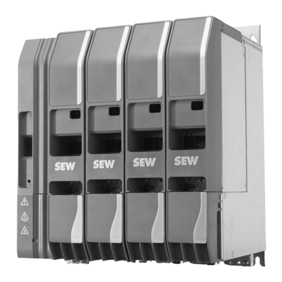
- Page 1 *25953486_0120* Drive Technology \ Drive Automation \ System Integration \ Services Compact Operating Instructions Application Inverter ® MOVIDRIVE modular Edition 01/2020 25953486/EN...
- Page 2 SEW-EURODRIVE—Driving the world...
-
Page 3: Table Of Contents
Table of contents Table of contents General information........................ 4 Scope of this documentation................... 4 Structure of the safety notes ................... 4 Safety notes .......................... 6 Preliminary information .................... 6 Duties of the user...................... 6 Target group ........................ 7 Designated use ....................... 7 Functional safety technology .................. 9 Transport......................... 9 Installation/assembly....................... 9 Electrical installation ..................... 10... -
Page 4: General Information
General information Scope of this documentation General information Scope of this documentation This documentation comprises the general safety notes and selected information re- ® garding the MOVIDRIVE modular application inverter. • Please note that this documentation does not replace the detailed operating in- structions. - Page 5 General information Structure of the safety notes 1.2.2 Structure of section-related safety notes Section-related safety notes do not apply to a specific action but to several actions pertaining to one subject. The hazard symbols used either indicate a general hazard or a specific hazard.
-
Page 6: Safety Notes
Safety notes Preliminary information Safety notes Preliminary information The following general safety notes serve the purpose of preventing injury to persons and damage to property. They primarily apply to the use of products described in this documentation. If you use additional components, also observe the relevant warning and safety notes. -
Page 7: Target Group
Safety notes Target group Target group Specialist for me- Any mechanical work may be performed only by adequately qualified specialists. Spe- chanical work cialists in the context of this documentation are persons who are familiar with the design, mechanical installation, troubleshooting, and maintenance of the product who possess the following qualifications: •... - Page 8 In this control mode only applications of horizontal materials handling are permitted. 2.4.2 Restrictions under the European WEEE Directive 2012/19/EU You may use options and accessories from SEW-EURODRIVE exclusively in connec- tion with products from SEW-EURODRIVE. ® Compact Operating Instructions – MOVIDRIVE...
-
Page 9: Functional Safety Technology
Safety notes Functional safety technology Functional safety technology The product must not perform any safety functions without a higher-level safety sys- tem, unless explicitly allowed by the documentation. Transport Inspect the shipment for damage as soon as you receive the delivery. Inform the ship- ping company immediately about any damage. -
Page 10: Electrical Installation
Safety notes Electrical installation Electrical installation Ensure that all of the required covers are correctly attached after carrying out the elec- trical installation. Make sure that preventive measures and protection devices comply with the applica- ble regulations (e.g. EN 60204-1 or EN 61800-5-1). 2.8.1 Required preventive measure Make sure that the product is correctly attached to the ground connection. -
Page 11: Startup/Operation
Safety notes Startup/operation 2.10 Startup/operation Observe the safety notes in chapters Startup and Operation in this documentation. Make sure the connection boxes are closed and screwed before connecting the sup- ply voltage. Depending on the degree of protection, products may have live, uninsulated, and sometimes moving or rotating parts, as well as hot surfaces during operation. -
Page 12: Movidrive
® MOVIDRIVE modular type code ® MOVIDRIVE modular type code ® The following type code applies to MOVIDRIVE modular. Example: MDA90A-0080-503-X-S00 ® Product family • MD = MOVIDRIVE Device type • A = Single-axis module • C = Capacitor module •... -
Page 13: Installation
Installation Mechanical installation Installation Mechanical installation CAUTION Risk of injury to persons and damage to property. Never install defective or damaged application inverters. • Before installing modules, check them for external damage. Replace any dam- aged modules. NOTICE Risk of damage to property due to mounting surface with poor conductivity. Damage to the application inverter. - Page 14 Installation Mechanical installation Mounting grid 27021610488337547 For dimension sheets of the application inverters, refer to chapter "Technical data". ® Compact Operating Instructions – MOVIDRIVE modular...
- Page 15 Installation Mechanical installation 4.1.2 Minimum clearance and mounting position When installing the modules in the control cabinet, observe the following: • To ensure unobstructed cooling, leave a minimum clearance of 100 mm above and below the module housings. Make sure air circulation in the clearance is not impaired by cables or other installation equipment.
-
Page 16: Electrical Installation
Installation Electrical installation Electrical installation DANGER There may be dangerous voltages inside the devices and at the terminal strips after the complete axis system has been disconnected from the power supply. Severe or fatal injuries from electric shock. To prevent electric shocks: •... - Page 17 Installation Electrical installation INFORMATION Installation with protective separation. The application inverter meets all requirements for protective separation of power and electronics connections in accordance with EN 61800-5-1. The connected signal circuits and the DC 24 V voltage supply must meet the requirements according to SELV (Safety Extra Low Voltage) or PELV (Protective Extra Low Voltage) to ensure protective separation.
- Page 18 Installation Electrical installation 4.2.1 General information • Take suitable measures to prevent the motor starting up inadvertently, for example by removing the electronics terminal block X20 on the axis module. You must provide additional safety features depending on the application, to prevent pos- sible injuries and damage to machines.
- Page 19 Installation Electrical installation 4.2.3 Line connection For the terminal assignment for line connection of the various sizes, refer to the chapter "Terminal assignment". For operation without line contactor, observe the specifications in the chapter "Protec- tion of braking resistor against thermal overload". Observe a minimum switch-off time of 10 s for the power supply module/the applica- tion inverter.
- Page 20 Installation Electrical installation 4.2.4 24 V supply voltage 24 V supply voltage without master module ® MOVIDRIVE modular requires an external 24 V supply voltage. Us the following in- stallation material for the connection: • M4 fork-type or ring lugs with insulating collar and a cable cross-section of maxi- mum 4 mm •...
- Page 21 Installation Electrical installation The connection is established either one-sided at the power supply module, or two- sided at the power supply module and the last axis module in the axis system, see the following figure for more details. RUN ERR RUN ERR RUN ERR –...
- Page 22 Installation Electrical installation 24 V supply voltage with master module UHX45A/MDM90A L/ A RUN ERR RUN ERR L/ A L/ A UHX45A-N – 9007220204831115 External DC 24 V supply at X5_A DC 24 V fuse X5_B → X5: DC 24 V supply voltage UHX45A Only use the connection cable included in the delivery to connect the 24 V supply of ®...
- Page 23 Installation Electrical installation ® PLUS 4.2.5 System bus EtherCAT /SBus ® PLUS For connecting the EtherCAT /SBus system bus, SEW‑EURODRIVE recommends using only prefabricated cables from SEW‑EURODRIVE. NOTICE Use of wrong cables Damage to the application inverter Only 4-pole cables are permitted to be used as system bus cables [2]. If an 8-pole cable is used, malfunctions or failures may occur at the connected devices.
- Page 24 Installation Electrical installation The connectors of the module bus cables are red and black to simplify correct attach- ment of the cables; see the following figure. • The black connectors must be plugged into the bus input X30 IN. • The red connectors must be plugged into the bus output X30 OUT.
- Page 25 In variant 1 and 2 the main row and auxiliary row must be connected as in variant 3 if the IP20 degree of protection is required. For the two-row design in a control cabinet, cable sets from SEW-EURODRIVE must be used, see chapter "Cable sets and accessories" (→ 2 34).
- Page 26 Installation Electrical installation Variant 2 Auxiliary row MDC90A-0001-50X-X-000 Use is mandatory - MDA90A-0020 – 0120-.. Maximum 8 modules - MDD9.A-0020 – 0080-.. RUN ERR RUN ERR RUN ERR - MDA90A-0160 – 0240-.. Maximum 2 modules - MDA90A-0320-.. Maximum 1 module Total nominal DC link current in auxiliary row: Max. 46 A Connection of main row and aux- iliary row...
- Page 27 Installation Electrical installation Variant 3 Auxiliary row MDC90A-0001-50X-X-000 Use is mandatory - MDA90A-0020 – 0120-.. Maximum 8 modules - MDD9.A-0020 – 0080-.. - MDA90A-0160 – 0240-.. Maximum 4 modules RUN ERR RUN ERR RUN ERR - MDA90A-0320 – 0480-.. Maximum 2 modules Total nominal DC link current in auxiliary row: Max. 109 A Connection of main row and aux- iliary row...
- Page 28 This variant is used if there is a large distance of up to 50 m between the main row and the auxiliary row. Applications in this design must be tested by SEW-EURODRIVE for the individual ap- plication. Contact SEW-EURODRIVE.
- Page 29 Installation Electrical installation Installation ® A MOVIDRIVE modular axis system is designed so that the axis modules must be mounted in descending order of the nominal DC link current. If the width of the axis system is wider than the available control cabinet width, it is possible to install some of the modules in a second row (auxiliary row).
- Page 30 Installation Electrical installation Connection to the DC link connection RUN ERR RUN ERR RUN ERR RUN ERR RUN ERR RUN ERR RUN ERR 28834999563 Main row Auxiliary row Connection main row and auxiliary row with DPC34A cable set Use the DCP34A cable set for the connection of the main row and auxiliary row. •...
- Page 31 Installation Electrical installation P o w e r 2 4 V G N D 28990915211 ® Compact Operating Instructions – MOVIDRIVE modular...
- Page 32 Installation Electrical installation Connection main row and auxiliary row with DCP35A cable set and connection unit 28910504203 • Use the screws [2] to screw the 3 conductor rails [1] to the insulator [3]. The tight- ening torque is 2.5 – 3 Nm. ®...
- Page 33 Installation Electrical installation • The DC link connections U + and U - must be twisted 3 times, see the following figure. PE +Uz -Uz 28911898379 • Use the screws [5] to screw the 3 prefabricated DC link connections [4] to the con- ductor rails [1].
- Page 34 Installation Electrical installation Cable sets and accessories DCP34A cable set, part number: 28261631 Cables 1× PVC conductor H07V-K, color: black, identification: Uz- 1× PVC conductor H07V-K, color: black, identification: Uz+ 1× PVC conductor H07V-K, color: green/yellow, identification: PE Cross section 16 mm Connection Crimping cable lug M6...
-
Page 35: Braking Resistors
Installation Braking resistors Braking resistors The supply cables to the braking resistors carry a high pulsed DC voltage during nom- inal operation. DANGER Dangerous pulsed DC voltage of up to 970 V. Severe or fatal injuries from electric shock. To prevent electric shocks: •... - Page 36 Installation Braking resistors 4.3.1 Protection against thermal overload of the braking resistor INFORMATION Guards for power supply modules with a nominal power of 50 kW and 75 kW It is not permitted to separate the connection between power supply module and bra- king resistor.
- Page 37 Installation Braking resistors • Set the control knob of the thermal circuit breaker TCB to the tripping current I the connected braking resistor. Set the scaling 40 °C. • After all cables are connected, the 3 upper screw holes must be covered with 3 touch guard caps.
- Page 38 Installation Braking resistors Internal temperature switch -T MDP90A-0100-.. power supply module If an BW...-T braking resistor with internal temperature switch is used with a 10 kW power supply module, there are 3 possible connections. Connection 1 Connection 2 Connection 3 24 V OUT 24 V OUT MDP90A...
- Page 39 Installation Braking resistors – If the thermal circuit breaker trips, there is no response in the power supply module and the axis modules. INFORMATION The braking resistor integrated in the MDP90A-0100-...-C00 power supply module is protected by the thermal protection. ®...
- Page 40 Installation Braking resistors MDP90A-0250, 0500, 0750, 1100 power supply module If an BW...-T braking resistor with internal temperature switch is used with a 25 – 110 kW power supply module, there are 3 possible connections. Connection 1 Connection 2 Connection 3 24 V OUT MDP90A MDP90A...
- Page 41 Installation Braking resistors – If the thermal circuit breaker trips, there is no direct response in the application inverter. ® Compact Operating Instructions – MOVIDRIVE modular...
- Page 42 Installation Braking resistors External bimetallic relay MDP90A-0100-.. power supply module If an external bimetallic relay is used with a 10 kW power supply module, there are 3 possible connections. Connection 1 Connection 2 Connection 3 24 V OUT 24 V OUT MDP90A MDP90A MDP90A...
- Page 43 Installation Braking resistors – This does not require a response by the PLC. – If the thermal circuit breaker trips, there is no response in the power supply module and the axis modules. ® Compact Operating Instructions – MOVIDRIVE modular...
- Page 44 Installation Braking resistors MDP90A-0250, 0500, 0750, 1100 power supply module If an external bimetallic relay is used with a 25 – 110 kW power supply module, there are 3 possible connections. Connection 1 Connection 2 Connection 3 24 V OUT MDP90A MDP90A MDP90A X7:2 -Temp_R X7:2 -Temp_R X7:2 -Temp_R...
-
Page 45: Terminal Assignment
Installation Terminal assignment – If the thermal circuit breaker trips, there is no direct response in the application inverter. Terminal assignment INFORMATION Reference potentials inside the device: The device internal reference potential is designated as GND in the following table. All reference potentials GND are internally connected to PE. - Page 46 Installation Terminal assignment 4.4.1 Terminal assignment at MDP power supply module Representa- Terminal Connec- Brief description tion tion X1:L1 X1:L2 Line connection MDP90A-0100-.. (size 1) X1:L3 PE connection X1:L1 X1:L2 Line connection MDP90A-0250-.. (size 2) X1:L3 PE connection L1 L2 L3 X1:1 X1:2 Line connection MDP90A-0500 –...
- Page 47 Installation Terminal assignment Representa- Terminal Connec- Brief description tion tion X4:+U DC link connection X4:-U PE connection X4:+U DC link connection left side MDP90A-1100-.. (size 4) X4:-U PE connection X4:+U DC link connection right side MDP90A-1100-.. (size 4) X4:-U PE connection X5:24 V 24V_in 24 V...
- Page 48 Installation Terminal assignment 4.4.2 Terminal assignment at MDA single-axis module Representa- Terminal Connection Brief description tion X2:U X2:V Motor connection MDA90A-0020 – 0240-.. (Sizes 1, 2) X2:W PE connection X2:U X2:V Motor connection MDA90A-0320 – 1000-.. (sizes 3 – 5) X2:W PE connection X2:U...
- Page 49 Installation Terminal assignment Representa- Terminal Connection Brief description tion SEW‑EURODRIVE Service interface X20:1 DI00 Digital input 1, with fixed assignment "Output stage en- able" X20:2 DI01 Digital input 2, fixed setpoints – positive direction of rota- tion X20:3 DI02 Digital input 3, fixed setpoints – negative direction of rotation X20:4 DI03...
- Page 50 Installation Terminal assignment Representa- Terminal Connection Brief description tion X15:1 A (cos+) (K1) Signal track A (cos+) (K1) X15:2 B (sin+) (K2) Signal track B (sin+) (K2) X15:3 C (K0) Signal track C (K0) X15:4 DATA+ Data cable for electronic nameplate X15:5 Reserved –...
- Page 51 Installation Terminal assignment Representa- Terminal Connection Brief description tion X15:1 A (cos+) (K1) Signal track A (cos+) (K1) X15:2 B (sin+) (K2) Signal track B (sin+) (K2) X15:3 Reserved – X15:4 DATA+ Data line RS485 X15:5 Reserved – X15:6 -TEMP_M Motor temperature evaluation X15:7 Reserved...
- Page 52 Installation Terminal assignment 4.4.3 Terminal assignment at MDD double-axis module Representa- Terminals Connection Brief description tion X2_1:U X2_2:U Motor connection MDD9.A-0020 – 0080-.. X2_1:V X2_2:V (Sizes 1, 2) X2_1:W X2_2:W PE connection X4:+U DC link connection X4:-U PE connection X5:24 V 24V_in DC 24 V supply voltage 24 V...
- Page 53 Installation Terminal assignment Representa- Terminals Connection Brief description tion X21_1:1 X21_2:1 DO00 Digital output 1, ready for operation X21_1:2 X21_2:2 DO01 Digital output 2, output stage enable X21_1:3 X21_2:3 DO02 Digital output 3, error X21_1:4 X21_2:4 DO03 Digital output 4, STO active X21_1:5 X21_2:5 Digital output 5, reference potential...
- Page 54 Installation Terminal assignment Representa- Terminals Connection Brief description, motor encoder sin/cos tion encoder, TTL encoder X15_1:1 X15_2:1 A (cos+) (K1) Signal track A (cos+) (K1) X15_1:2 X15_2:2 B (sin+) (K2) Signal track B (sin+) (K2) X15_1:3 X15_2:3 C (K0) Signal track C (K0) X15_1:4 X15_2:4 DATA+...
- Page 55 Installation Terminal assignment Representa- Terminals Connection Brief description motor encoder ® tion HIPERFACE and SEW‑EURODRIVE en- coder (RS485) X15_1:1 X15_2:1 A (cos+) (K1) Signal track A (cos+) (K1) X15_1:2 X15_2:2 B (sin+) (K2) Signal track B (sin+) (K2) X15_1:3 X15_2:3 Reserved –...
- Page 56 Installation Terminal assignment 4.4.4 Terminal assignment of MDC90A-0001/0002-.. capacitor module Representa- Terminal Connec- Brief description tion tion X4:+U DC link connection X4:-U PE connection X4_A:+ Connection of safe brake module X4_A:- PE connection X5:24 V 24V_in 24 V +24 V supply voltage X5:GND ®...
-
Page 57: Wiring Diagrams
Installation Wiring diagrams 4.4.5 Terminal assignment at master module UHX45A/MDM90A Representa- Terminal Connection Brief description tion X5_A:24V 24V_in External DC 24 V supply voltage from housing MD- M90A X5_A:GND GND Reference potential housing MDM90A X5_B:24V 24V_out Output of DC 24 V supply voltage from housing MD- M90A X5_B:GND GND Reference potential housing MDM90A... - Page 58 Installation Wiring diagrams Exemplary wiring of the MDP90A.. power connections with line contactor, line choke, and line filter U1 V1 W1 U2 V2 W2 L1 L2 L3 L1´ L2´ L3´ X1 L1 L2 L3 X2_1 X2_2 U V W U V W U V W 36028806497163019 Line contactor...
- Page 59 Installation Wiring diagrams Wiring the MDP90A-0250, 0500, 0750, 1100 power connections without line contactor Operation without line contactor is only possible for power supply modules of 25 kW of higher. U1 V1 W1 U2 V2 W2 L1 L2 L3 L1´ L2´ L3´ L1 L2 L3 X2_2 X2_1...
- Page 60 Installation Wiring diagrams Wiring of the MDP90A-..-C00 power connections using the integrated braking resistor U1 V1 W1 U2 V2 W2 L1 L2 L3 L1´ L2´ L3´ L1 L2 L3 X2_1 X2_2 U V W U V W U V W 27021607242286475 Line contactor Line choke (optional)
- Page 61 Installation Wiring diagrams Wiring of the MDP90A-..-C00 power connections using the external braking resistor U1 V1 W1 U2 V2 W2 L1 L2 L3 L1´ L2´ L3´ L1 L2 L3 X2_1 X2_2 U V W U V W U V W 36028806505258635 Line contactor Line choke (optional)
- Page 62 Installation Wiring diagrams 4.5.3 Brake control Legend: Cut-off in the DC and AC circuits (rapid brake application) Cut-off in the DC circuit Brake BS = accelerator coil TS = coil section DC brake with one brake coil Auxiliary terminal strip in terminal box Control cabinet limit White Blue...
- Page 63 Installation Wiring diagrams BMK. brake control DB00 BMKB 14324495755 BMV brake control – 2 coils DB00 DC 24 V 14373482507 ® Compact Operating Instructions – MOVIDRIVE modular...
- Page 64 Installation Wiring diagrams BMV brake control – 1 coil DB00 DC 24 V 14373494923 BMS, BME brake control DB00 14324554891 ® Compact Operating Instructions – MOVIDRIVE modular...
- Page 65 Installation Wiring diagrams BMP brake control DB00 14324544523 BG, BGE brake control DB00 14324565259 ® Compact Operating Instructions – MOVIDRIVE modular...
- Page 66 Installation Wiring diagrams BSG brake control DC 24 V DB00 14324597131 Direct control DC 24 V brake If the system complies with the following specifications for direct brake control, a BK or BP brake (holding brake) can also be controlled directly via the brake output of an ap- plication inverter.
- Page 67 Installation Wiring diagrams 4.5.4 Electronics connection MDP90A.. power supply module Wiring the control electronics For the terminal assignment and connections, refer to chapter "Terminal assign- ment" (→ 2 45). + T emp_R -T emp_R reserved reserved X30 OUT X30 IN DC 24 V +24 V 54043209842314507 Connection +24 V supply voltage...
- Page 68 Installation Wiring diagrams 4.5.5 Electronics connection MDA90A.. single-axis module Wiring the control electronics For the terminal assignment and connections, refer to the chapter "Terminal assign- ment" (→ 2 45). "Output stage enable" permanently assigned DI00 Fixed setpoints – positive rotation direction DI01 Fixed setpoints – negative rotation direction DI02 DI03 Fixed speed setpoint bit 0...
- Page 69 Installation Wiring diagrams F_STO_P1 F_STO_M F_STO_P2 24VSTO_OUT X30 OUT X30 IN Brake control Reference potential Motor temperature evaluation Reference potential 9007224862221067 Connection for Safe Torque Off (STO) With installed CS.A card, the cable bridges are removed at the factory. If no CS.A card is installed upon delivery, the cable bridges are installed at the factory Brake control and motor temperature monitoring ®...
- Page 70 Installation Wiring diagrams 4.5.6 MDD9.A.. double-axis module electrical connection Wiring the control electronics For the terminal assignment and connections, refer to the chapter "Terminal assign- ment" (→ 2 45). X20_1 X20_2 "Output stage enable" permanently assigned DI00 DI00 Fixed setpoints – positive rotation direction DI01 DI01 Fixed setpoints –...
- Page 71 Installation Wiring diagrams F_STO_P1 F_STO_P1 F_STO_M F_STO_M F_STO_P2 F_STO_P2 24VSTO_OUT 24VSTO_OUT X6_2 X6_1 X30 OUT X30 IN X10_1 X10_2 Brake control Reference potential Motor temperature evaluation Reference potential X16_1 X16_2 25607711883 Connection for Safe Torque Off (STO) With installed CS.A card, the cable bridges are removed at the factory. If no CS.A card is installed upon delivery, the cable bridges are installed at the factory.
- Page 72 Installation Wiring diagrams 4.5.7 Connection diagram CIO21A and CID21A input/output card Digital inputs and outputs DI10 DI11 DI12 DI13 DO10 DO11 DO12 DO13 18014412829087243 Higher-level controller ® Compact Operating Instructions – MOVIDRIVE modular...
- Page 73 Installation Wiring diagrams Voltage input REF1 AI21 AI22 AI31 AI32 REF2 9007213575393675 Connection to the terminals AI31 and AI32 is carried out analogously to the connec- tion to the terminals AI21 and AI22 shown in the wiring diagrams. R > 5 kΩ REF1 AI21 AI22...
- Page 74 Installation Wiring diagrams Current input REF1 AI21 AI22 AI31 AI32 REF2 9007213575398539 Connection to the terminals AI31 and AI32 is carried out analogously to the connec- tion to the terminals AI21 and AI22 shown in the wiring diagrams. Observe the switch position of DIP switch S50 when activating the current input. Voltage output AOV2 AOC2...
- Page 75 Installation Wiring diagrams Current output AOV2 AOC2 AOV3 AOC3 18014412830272395 Connection to the terminals AOC3 and GND is carried out analogously to the connec- tion to the terminals AOC2 and GND shown in the wiring diagram. ® Compact Operating Instructions – MOVIDRIVE modular...
-
Page 76: Startup
Startup Assigning the EtherCAT®/SBusPLUS address at the axis module Startup Assigning EtherCAT®/ SBusPLUS address at the axis module ® PLUS Assigning the EtherCAT /SBus address at the axis module There are 2 hexadecimal address switches S1 and S2 installed in each axis module to ®... - Page 77 Startup Startup requirements Required software: ® • MOVISUITE standard engineering software from SEW‑EURODRIVE. ® Compact Operating Instructions – MOVIDRIVE modular...
-
Page 78: Operation
Operation General information Operation General information DANGER Dangerous voltages present at cables and motor terminals. Severe or fatal injuries from electric shock. • Dangerous voltages are present at the output terminals and the cables and motor terminals connected to them when the device is switched on. This also applies even when the device is inhibited and the motor is at standstill. -
Page 79: Operating Displays
Operation Operating displays Operating displays 6.2.1 Operating states of the power supply module – 7-segment display Display Description State Comment/action Displays in normal operation Ready for operation (ready). No fault/warning: U ≥ 100 V. Only status display. Display Description State Comment/action Displays of different device statuses DC link voltage is below 100 V. - Page 80 Operation Operating displays Display Description State Comment / action Startup state Startup state is active. Flashing STO active The function Safe Torque Off is active. Flashing Synchronization with bus is incor- • Check the bus connection. Flashing rect. Process data processing not •...
- Page 81 Operation Operating displays Display Description State Comment / action Stop default For further information, refer to the Drive function (FCB) "Default stop" active, if not FCB description. other FCB is selected and the system is "ready". Manual mode Manual mode active Speed control Speed control with internal ramp generator.
-
Page 82: Service
Service Extended storage Service Extended storage The following table shows the time intervals and maintenance works that are relevant for extended storage of the application inverter modules. Modules Time interval Maintenance MDP90A...-C00/0 Line connections: Connect the device MDP90A..Every 2 years to the line voltage for 5 minutes. -
Page 83: Shutdown
Service Shutdown Shutdown To shut down the application inverter, de-energize the application inverter using ap- propriate measures. WARNING Electric shock due to incompletely discharged capacitors. Severe or fatal injuries. • Observe a minimum switch-off time of 10 minutes after disconnecting the power supply. - Page 88 SEW-EURODRIVE—Driving the world SEW-EURODRIVE GmbH & Co KG Ernst-Blickle-Str. 42 76646 BRUCHSAL GERMANY Tel. +49 7251 75-0 Fax +49 7251 75-1970 sew@sew-eurodrive.com www.sew-eurodrive.com...
Need help?
Do you have a question about the MOVIDRIVE modular and is the answer not in the manual?
Questions and answers