Sign In
Upload
Manuals
Brands
SEW-Eurodrive Manuals
Inverter
MOVIDRIVE modular
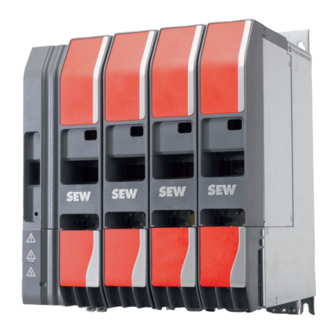
SEW-Eurodrive MOVIDRIVE modular Inverter Manuals
Manuals and User Guides for SEW-Eurodrive MOVIDRIVE modular Inverter. We have
2
SEW-Eurodrive MOVIDRIVE modular Inverter manuals available for free PDF download: Product Manual, Compact Operating Instructions
SEW-Eurodrive MOVIDRIVE modular Product Manual (509 pages)
Brand:
SEW-Eurodrive
| Category:
Inverter
| Size: 51 MB
Table of Contents
Table of Contents
3
1 Product Description
6
MOVIDRIVE Modular at a Glance
9
Power Supply Module with Controlled DC Link
9
Power Supply Modules
9
Axis Modules
10
Power Supply Modules with Supply and Energy Recovery
10
Capacitor Module for Two-Row Design
11
Capacitor Module for Energy Storage
12
Master Module
12
Cards
13
Controllers
14
Accessories
15
Device Data
17
MDP90A Power Supply Modules
17
Product Overview MOVIDRIVE Modular
17
Properties
17
Features
18
MDA90A- Single-Axis Modules
18
MDD9.A- Double-Axis Modules
19
Axis Modules with Device Profile Cia402
20
Device Data of the Double-Axis Module
20
Device Data of the Single-Axis Module
20
Master Module UHX45A/MDM90A
21
MDC90A-0001/0002-50X-X-000 Capacitor Module
21
CES11A Multi-Encoder Card
22
CID21A Input/Output Card
22
CIO21A Input/Output Card
22
Product Overview Accessories
22
Safety Cards CS..A
23
Lifting Eye
24
Special Aspects When Transporting the Devices
24
FCB Concept
25
Description of the Fcbs
26
Setpoints and Limits in the Fcbs
31
Control Mode
32
Description of the Control Modes
32
Speed Control
32
U/F
32
Position Control
33
Torque Control
33
Vfc
33
Cfc
34
Elsm
34
Rotor Adjustment/Rotor Position Measurement
34
Flying Start Function
35
Characteristic Values for Dynamics
36
Characteristic Values for Setpoint Resolution
36
Characteristics of the Control Modes
36
Overview of the Control Modes
36
Characteristic Values for Accuracy of Torque and Speed
37
Maximum Output Frequency
37
Fcbs that Can be Activated for Selected Control Mode
38
Energy-Saving Functions
39
Flux Optimization
39
Standby Mode
39
Energy Consumption in Standby Operation
40
Module Bus
41
Digital Motor Integration with MOVILINK DDI Interface
42
Device Replacement
44
Circle View
45
MOVISUITE Engineering Software
45
Tree View
45
2 Technical Data
48
Markings
48
Basic Device
48
Braking Resistors BR
49
TCB Thermal Circuit Breaker
49
NF Line Filter
50
ND Line Choke
50
General Technical Data
51
Technical Data of MDP Power Supply Modules
52
Performance Data
52
Electronics Data – Signal Terminals
53
Technical Data of MDA and MDD Axis Modules
54
MDA Performance Data
54
MDD Performance Data
56
Electronics Data – Drive Safety Functions
58
Different Functionality of the Axis Modules MDA/MDD
59
Technical Data of the MDC90A-0001/0002-Capacitor Modules
60
Technical Data of the Master Module UHX45A/MDM90A
61
Dimension Sheets of the Power Supply Modules
62
Dimension Sheets of the Axis Modules
68
Dimension Sheet of the Capacitor Modules
76
Dimension Sheet of the Master Module
77
Technical Data of the Cards
78
CIO21A and CID21A Input/Output Cards
78
Safe Digital Inputs
81
Sensor Supply
82
Safe Digital Outputs
82
Technical Data of Encoder Interfaces
83
Technical Data of Braking Resistors, Filters and Chokes
84
Braking Resistors Type BW.../BW...-T
84
General
84
UL and Cul Approval
84
Technical Data and Assignment to an Inverter
85
Assignment
85
Dimension Sheets and Dimensions
88
Wire Resistor
88
Grid Resistor Mounting Position 1
88
Grid Resistor Mounting Position 2
89
Touch Guard BS..
90
Description
90
Dimension Sheet BS..
90
Mounting Rail Installation
90
TCB Thermal Circuit Breaker Option
91
Technical Data of Signal Contact
92
Dimension Sheet
92
Line Filter
93
Assignment to an Inverter
93
Line Choke
95
3 Configuration
97
SEW-Workbench
97
Schematic Workflow for Project Planning
98
Drive Selection
99
General Requirements for Motors
99
Motors that Can be Connected
99
Dielectric Strength of the Motor
99
Requirements for Third-Party Motors
100
Thermal Motor Protection
100
Startup of Third-Party Motors
101
Asynchronous Motors
101
Synchronous Motors
101
Group Drive and Multi-Motor Drive
102
Group Drive of Asynchronous Motors
102
Multi-Motor Drive of Asynchronous Motors
102
Connecting Explosion-Proof AC Motors
103
General Requirements for Encoders
104
Valid Motor Encoders from SEW‑EURODRIVE
104
Encoder with Electronic Nameplate
104
General Requirements for the Brake Control
105
Recommendations for Motor and Inverter Selection
106
Thermal Limit Characteristic Curve
106
Dynamic Limit Characteristic Curve
106
Typical Characteristic Curve of Asynchronous Motors
106
Motor Selection for Asynchronous Motors
107
Asynchronous Motors in Control Mode VFC
107
Typical Characteristic Curve of Synchronous Motors
107
Asynchronous Motors in Control Mode CFC
108
Standard Asynchronous Motors in Control Mode CFC
108
Asynchronous Servomotors in Control Mode CFC
108
Synchronous Servomotors in Control Mode CFC
109
Synchronous Servomotors in Control Mode ELSM
110
Requirements Regarding Motor Encoder
110
Motor-Inverter Assignments
111
Technical Data DRN.. Motors
111
IE3 DRN.. Motors, 400 V, 50 Hz, 4-Pole
112
Information on Motors
112
Further Information on Motors and Brakemotors
113
Motor-Inverter Assignments DRN.. Motors, F= 4 Khz
114
MOVIDRIVE Modular – 400 V, 50 Hz, VFC
114
Technical Data of DR2S.. Motors
116
IE1 DR2S.. Motors, 400 V, 50 Hz, 4‑Pole
116
Motor-Inverter Assignments DR2S.. Motors
117
Technical Data of DRL.. Motors
118
4-Pole DRL.. Servomotors/Brakemotors for 400 V, 50 Hz
120
Motor-Inverter Assignments DRL.. Motors, F= 4 Khz
122
Technical Data of DR2L Motors
132
Key to the Data Tables of DR2L Asynchronous Servomotors
132
DR2L Motors, 400 V, 50 Hz, 4-Pole
132
Motor/Inverter Assignments of DR2L.. Motors, Fpwm = 4 Khz
134
Technical Data of CMP Motors
137
CMP40 – CMP112, 400 V System Voltage
138
Motor-Inverter Assignments CMP Motors, 400 V, F= 4 Khz
140
Selecting an Axis Module
150
Overload Capacity
151
Examples of Permitted Current Profiles
151
Derating Due to the Rotary Field Frequency
152
Derating Due to the Installation Altitude
153
Derating Due to the Line Voltage
153
Power Supply Module Selection
154
Power Curve of the DC Link
154
Sum of the Nominal DC Link Current of the Connected Axis Modules
155
Load Cycle with Base Load
155
Operation Without Line Choke
156
Operation with Line Choke
156
Assignment of the Maximum Axis Size to the Power Supply Module
157
Maximum Number of Axis Modules and Total Cable Length
157
Current-Carrying Capacity of Integrated Braking Resistor for MDP90-C00
157
Braking Resistor Selection
158
General Information
158
Table of Braking Resistors
158
Selection Criteria
158
Continuous Braking Power
159
Peak Braking Power
159
Current-Carrying Capacity of the Brake Chopper
159
Permitted Installation of Braking Resistors
160
Flat Type Resistor
161
Supply Cable for Braking Resistor
162
Protection against Thermal Overload of the Braking Resistor
162
Supply System Cable and Motor Cable
163
Recommended Cross Section for Nominal Operation
163
Motor Cable
164
Cable Length
164
Voltage Drop
165
Signal Lines
166
EMC-Compliant Installation According to en 61800-3
166
Encoder Cables
166
Digital Inputs/Outputs and DC 24 V Supply
166
Line Components
167
Line Fuses, Fuse Types
167
Line Contactor
168
MDP Power Supply Module 10 Kw
168
MDP Power Supply Module ≥ 25 Kw
168
Residual Current Device
170
24 V Supply Voltage Selection
171
Project Planning for 24 V Supply Power
171
Supply of the 24 V Supply Voltage
172
One-Sided Supply
172
Two-Sided Supply
173
Supply of the 24 V Supply Voltage at the Master Module
174
Power Consumption of the 24 V Supply
175
Power Consumption of the Directly Connected 24 V Brakes
176
Requirements on the Tolerance of the 24 V Voltage Supply
176
Project Planning Example
177
Arrangement of the Modules Within the Axis System
178
Arrangement of the Axis Modules Within the Axis System
178
Particularities of the DC Link Connection
179
Use of Axis Module MDA90A-1000 at MDP90A-1100 Power Supply Module
179
Adapter Connectors of the DC Link Connection
180
Examples of the DC Link Busbar with Different Bar Widths
181
Connecting a Safe Brake Module to the DC Link
184
Two-Row Design
185
Design Variants in a Control Cabinet
185
Design Variant with Large Distance between Main Row and Auxiliary Row
188
Cable Sets and Accessories
189
+24 V Supply Voltage
189
Maximum Permitted Distance of the Module Rows
189
4 Prefabricated Cables
190
Meaning of the Symbols
190
Power Cables for CMP Motors
191
Overview
191
Motor Cable with Connector on Motor End
192
Motor Cable Illustration
192
Types of CMP Motor Cables
192
Illustration of Motor Extension Cable
193
Types of CMP Motor Extension Cables
193
Brakemotor Cables for BP/BK Brake with Connector at Motor End
194
Figure of CMP Brakemotor Cables
194
Types of CMP Brakemotor Cables
194
Brakemotor Cables for by Brake with Connector at Motor End
195
Extension Cable for BP, BK, by Brakes
196
Illustration of Brakemotor Extension Cable
196
Types of CMP Brakemotor Extension Cables
196
Encoder Cables for CMP Motors
197
Resolver
198
Illustration of RH1M Resolver Cable
198
Types of RH1M Resolver Cables
198
Illustration of RH1M Extension Cable
198
HIPERFACE Encoders
199
Illustration of HIPERFACE Encoder Cable
199
Types of HIPERFACE Encoder Cables
199
Illustration of HIPERFACE Encoder Extension Cable
199
Single-Cable Technology for CMP Motors
200
Types of Motor/Brakemotor Cable
200
Types of Extension Cables
200
Power Cables for CFM Motors
201
Motor Cable Types
202
Motor Extension Cable
203
Brakemotor Cable
204
Illustration of Brakemotor Cable
204
Types of Brakemotor Cables
204
Brakemotor Extension Cables
205
Types of Brakemotor Extension Cables
205
Encoder Cables for CFM Motors
206
Illustration of RH1M/RH1L Resolver Cable
207
Illustration of RH1M/RH1L Extension Cable
207
Illustration of RH1M/RH1L Resolver Cable for Terminal Box
207
Types of RH1M/RH1L Resolver Cables
207
Illustration of HIPERFACE Encoder Cable for Terminal Box
208
Types of HIPERFACE Encoder Extension Cables
208
Types of HIPERFACE Encoder Cables for Terminal Box
208
Encoder Cables for CFM.. Motors
208
Encoder Cables for DR Motors
209
Encoder Cable with Connection Cover and D-Sub
213
Illustration of Encoder Cable
213
Types of Encoder Cables
213
Encoder Cable with Conductor End Sleeves and D-Sub
214
Encoder Cable with M23 and D-Sub
214
Encoder Extension Cable with Connection Cover and M23
214
Illustration of Encoder Extension Cable
214
Encoder Extension Cable with Conductor End Sleeves and M23
215
Types of Encoder Extension Cables
215
Encoder Extension Cable with Two M23
216
Encoder Extension Cable with M23 and D-Sub
216
Cables for MOVILINK DDI
217
Motor Cable Connections for DRN Motors W/O Brake with MOVILINK DDI
221
Motor Cable Connection for DRN Motors with be Brake with MOVILINK DDI
222
Motor Cable Connections for CMP Motors Without Brake with MOVILINK DDI
223
Motor Cable Connections for CMP Motors W BK/BP Brake with MOVILINK DDI
224
Motor Cable Connections for CM3C Motors W/O Brake with MOVILINK DDI
225
Motor Cable Connection for CM3C Motors with BK Brake and MOVILINK DDI
226
Motor Cable Connection for CM3C Motors with BZ Brake with MOVILINK DDI
227
System Bus and Module Bus Cables
228
Example of a System Bus and Module Bus Cabling
228
System Bus Cable
229
Figure of the Cable
229
RJ45 Connector
230
Pin Assignment
230
Module Bus Cable
231
Figure
231
About this Documentation
232
Structure of the Safety Notes
232
Meaning of Signal Words
232
5 General Information
232
Decimal Separator in Numerical Values
233
Structure of Section-Related Safety Notes
233
Structure of Embedded Safety Notes
233
Meaning of the Hazard Symbols
233
Rights to Claim under Limited Warranty
234
Content of the Documentation
234
Other Applicable Documentation
234
Product Names and Trademarks
234
Copyright Notice
234
6 Safety Notes
235
Preliminary Information
235
Duties of the User
235
Target Group
236
Designated Use
236
Specialist for Mechanical Work
236
Specialist for Electrotechnical Work
236
Hoist Applications
237
Restrictions under the European WEEE Directive 2012/19/EU
237
Application in ELSM Control Mode
237
Functional Safety Technology
238
Transport
238
Installation/Assembly
238
Restrictions of Use
238
Electrical Installation
239
Protective Separation
239
Required Preventive Measure
239
Stationary Application
239
Startup/Operation
240
Energy Storage Unit
240
7 Device Structure, Axis System Structure
241
Connection Variants
241
Axis System with MOVI-C CONTROLLER Power/Power Eco MOVIDRIVE Modular
242
MOVIDRIVE Modular and MOVIDRIVE System
243
Axis System with Master Module UHX45A/MDM90A MOVIDRIVE Modular
244
Axis System with MOVI-C CONTROLLER Advanced MOVIDRIVE Modular
246
Axis System with MOVI-C CONTROLLER Standard MOVIDRIVE Modular
248
MOVIDRIVE Modular Nameplates
250
Power Supply Module
250
System Nameplate
250
Performance Data Nameplate
250
Single-Axis Module
251
Double-Axis Module
252
MOVIDRIVE Modular Type Code
253
Device Structure of the MDP Power Supply Module
254
MDP90A-0100 (Size 1)
254
MDP90A-0100 with Integrated Braking Resistance
255
Mdp90A-0250
256
Mdp90A-0500, 0750
257
Mdp90A-1100
258
Device Structure of the MDA and MDD Axis Modules
259
MDA90A-0020, 0040, 0080, 0120 – Single-Axis Module
260
MDA90A-0160, 0240 – Single-Axis Module
261
MDA90A0-320, 0480 – Single-Axis Module
262
MDA90A0-0640 – Single-Axis Module
263
MDA90A-0640, 1000 – Single-Axis Module
264
MDA90A-1400, 1800 – Single-Axis Module
265
MDD9.A-0020, 0040 – Double-Axis Module
266
MDD9.A-0020, 0040, 0080 – Double-Axis Module
267
MDC Capacitor Module
269
Mdc90A-0001/0002-50X-X-000
269
Device Structure of Master Module UHX45A/MDM90A
270
Example for Axis System Connection Without Master Module
271
Example for Axis System Connection with Master Module
272
Card Slots
273
Single-Axis Modules
273
Double-Axis Modules
274
Installation Accessories
275
Standard Accessories
275
Available Accessories
278
Cable
278
Permitted Tightening Torques
279
Special Aspects When Transporting the Devices
280
Mechanical Installation
281
Hole Pattern
281
Mounting Grid
282
Minimum Clearance and Mounting Position
283
Covers
284
Removing the Safety Cover
284
Installing the Safety Cover
285
Touch Guards
286
Axis System with Master Module
286
Axis System Without Master Module
287
Power Connection Closing Cover
288
Closing Cover between MDA90A-1400 – 1800 and MDA90A-0020 – 0240
289
Front Cover
290
Protection Caps
291
Line Connection, Motor Connection
291
Braking Resistor Connection
291
Breaking out Templates
292
Control Cabinet Installation
293
Installing a Module
294
Installing Shield Plates
295
Bottom Shield Plate
295
Top Shield Plate
296
Removing the Covers
297
Removing the Touch Guards
298
Installing the Busbar
299
Installing Touch Guards
300
Installing Front Covers and Covers
302
Removing an Axis Module
302
Installation/Removal of the UHX45A
303
Electrical Installation
304
Installation with Protective Separation
305
Permitted Voltage Systems
306
Use in IT Systems
306
Line Connection
308
Power Connections
309
Connection with 1 Cable
309
Connection with 2 Cables
310
24 V Supply Voltage Without Master Module
311
24 V Supply Voltage with Master Module UHX45A/MDM90A
313
Connection of an Axis System
314
Two-Row Design with MDC90A
319
Installation
324
Connection to the DC Link Connection
325
Connection Main Row and Auxiliary Row with DPC34A Cable Set
325
Connection Main/Auxiliary Row with DCP35A Cable Set/Connection Unit
327
Installing Touch Guards and Closing Covers
330
With Master Module
330
Without Master Module
331
Motor Output
332
Output Brake Chopper
332
Temperature Evaluation of the Motor
332
Brake Output
332
Inputs/Outputs
333
System Bus Ethercat/Sbus
334
System Bus and Module Bus Cabling
334
Correct Cabling
335
Encoder
336
Installation Notes for Encoder Connection
336
Encoder Cable
336
On the Encoder/Resolver
336
Encoder Connection/Cable Lengths
337
Notes on MOVILINK DDI
338
Removing the Connector
338
Maximum Line Length
338
Self-Assembled Encoder Cables
339
Minimum Requirements for Encoder Cables
339
Installing Options and Accessories
340
Installing a Card
340
CIO21A and CID21A Input/Output Card
343
Short-Circuit Behavior of Digital Outputs
343
Short Circuit Behavior of Analog Outputs
343
Connecting Inductive Loads at Digital Outputs
343
CIO21A Terminal Assignment
344
Overview of Functions
346
Supported Encoder Types
346
Terminal Assignment of TTL, HTL, Sin/Cos Encoder
347
Terminal Assignment HIPERFACE and SEW‑EURODRIVE Encoder (RS485)
347
Terminal Assignment Endat Encoder
348
Terminal Assignment SSI Encoder
348
Terminal Assignment SSI and Sin/Cos Combination Encoders
349
Terminal Assignment Canopen Encoder
349
Safety Cards CSA
350
Braking Resistors
351
Thermal Protection with Flat-Type Resistors
353
External Thermal Circuit Breaker TCB
354
Power Supply Module MDP90A 10 Kw, 25 Kw, 110 Kw
354
Internal Temperature Switch -T
356
MDP90A-0100 Power Supply Module
356
MDP90A-0250, 0500, 0750, 1100 Power Supply Module
358
External Bimetallic Relay
360
Line Choke
364
Line Filter
364
EMC-Compliant Installation
365
Control Cabinet
366
HF Equipotential Bonding in the System
366
Cable Installation
366
Supply System Cable Connection
366
Line Filter Connection
367
Motor and Brake Connection
368
Control Cable Connection
368
Encoder Connection
368
Shielding Connection
369
Terminal Assignment
370
Terminal Assignment at MDP Power Supply Module
371
Terminal Assignment at MDA Single-Axis Module
373
Terminal Assignment at MDD Double-Axis Module
377
Terminal Assignment of MDC90A-0001/0002 Capacitor Module
381
Terminal Assignment at Master Module UHX45A/MDM90A
382
General Information on the Wiring Diagrams
383
Power Connection
383
Exemplary Wiring of the MDP90A.. Power Connections
384
Wiring MDP90A-0250/0500/0750/1100 Power Connections W/O Line Contactor
385
Wiring of MDP90A-C00 Power Connection with Integrated Braking Resistor
386
Wiring of MDP90A-C00 Power Connections with External Braking Resistor
387
Brake Control
388
BMK. Brake Control
389
BMV Brake Control – 2 Coils
389
BMV Brake Control – 1 Coil
390
BMS, BME Brake Control
390
BMP Brake Control
391
BG, BGE Brake Control
391
BSG Brake Control
392
Direct Control DC 24 V Brake
392
Electronics Connection MDP90A Power Supply Module
393
Wiring the Control Electronics
393
Electronics Connection MDA90A Single-Axis Module
394
MDD9.A Double-Axis Module Electrical Connection
396
Connection Diagram CIO21A and CID21A Input/Output Card
398
Digital Inputs and Outputs
398
Voltage Input
399
Current Input
400
Voltage Output
400
Current Output
401
Information Regarding UL
402
Field Wiring Power Terminals
402
Short Circuit Current Rating
402
Branch Circuit Protection
403
Motor Overload Protection
403
Ambient Temperature
403
9 Startup
405
Connecting Cables
405
Connecting Power
405
General
405
Lifting Applications
405
Assigning the Ethercat /Sbus PLUS Address at the Axis Module
406
Startup Requirements
407
Startup Procedure
408
Check List for Startup
411
Connection to the Engineering Software
411
10 Operation
412
General Information
412
7-Segment Display
413
Operating Displays
413
Fault Display
413
Fault Display at the Double-Axis Module
413
Operating States of the Power Supply Module – 7-Segment Display
414
Operating Displays of the Power Supply Module – LED Displays
414
Operating Displays of the Axis Module – 7-Segment Display
414
Faults at the Power Supply Module
417
Faults at the Single-Axis Module/Double-Axis Module
421
Fault 1 Output Stage Monitoring
421
Fault 3 Ground Fault
421
Fault 4 Brake Chopper
421
Fault 7 DC Link
422
Fault 8 Speed Monitoring
422
Fault 9 Control Mode
422
Fault 10 Data Flexibility
424
Fault 11 Temperature Monitoring
425
Fault 12 Brake
426
Error 13 Encoder 1 Fault
426
Fault 14 Encoder 2
431
Fault 16 Startup
435
Fault 17 Internal Processor Fault
437
Fault 18 Software Error
437
Fault 19 Process Data
438
Fault 20 Device Monitoring
439
Fault 21 Digital Motor Integration 1
440
Fault 22 Digital Motor Integration 2
441
Fault 23 Power Section
442
Error 24 Cam Switch
443
Fault 25 Parameter Memory Monitoring
443
Fault 26 External Fault
446
Fault 28 FCB Drive Functions
446
Fault 29 HW Limit Switches
448
Fault 30 Software Limit Switches
448
Fault 31 Thermal Motor Protection
449
Fault 32 Communication
451
Fault 33 System Initialization
452
Fault 34 Process Data Configuration
453
Fault 35 Function Activation
453
Fault 42 Lag Error
454
Fault 46 Safety Card
455
Fault 47 Supply Unit
455
Fault 48 Module Bus
456
Fault 50 I/O Card
456
Fault 51 Analog Processing
457
Fault 52 Explosion Protection Function Category 2
457
Fault at the Master Module UHX45A/MDM90A
459
Module Bus Faults
460
Grid Condition
460
DC Link Condition
460
Line Phase Failure
460
Responses to Fault Acknowledgement
461
Fault Acknowledgement at the Power Supply Module
461
Fault Acknowledgement at the Axis Modules
461
Software Reset/Restart
461
Warm Start
462
Default – Fault Response
463
Parameterizable Faults
463
Extended Storage
466
Electronics Service by SEW-EURODRIVE
466
Shutdown
467
Procedure in Case Maintenance Has Been Neglected
467
Using Energy Storage Units
467
Waste Disposal
468
12 Functional Safety
469
Integrated Safety Technology
469
Underlying Standards
469
Safe Condition
469
General Information
469
Schematic Representation of the Safety Concept
470
Drive Safety Functions
470
Safety Conditions
472
Restrictions
472
Approved Devices
473
Requirements for the Installation
473
Requirements for External Safety Controllers
474
Requirements for Startup
475
Requirements for Operation
476
Connection Designs
477
Requirements
477
Use of Safety Relays
477
Use of Safety Controllers
478
STO Signal for Group Disconnection
478
Wiring Diagrams
479
Delivery State
479
2-Pole Sourcing
479
2-Pole Sourcing/Sinking
479
Port X6 on the Device
480
STO Group Disconnection, 2-Pole, Sourcing
480
STO Group Disconnection, 2-Pole, Sourcing/Sinking
480
STO Group Disconnection, 1-Pole, Sourcing
480
Safety Characteristics
481
13 Appendix
483
Abbreviation Key
483
Index
485
14 Address List
492
Advertisement
SEW-Eurodrive MOVIDRIVE modular Compact Operating Instructions (88 pages)
Application inverter
Brand:
SEW-Eurodrive
| Category:
Inverter
| Size: 13 MB
Table of Contents
Table of Contents
3
General Information
4
Scope of this Documentation
4
Structure of the Safety Notes
4
Safety Notes
6
Preliminary Information
6
Duties of the User
6
Target Group
7
Designated Use
7
Functional Safety Technology
9
Transport
9
Installation/Assembly
9
Electrical Installation
10
Protective Separation
10
Startup/Operation
11
Movidrive
12
Installation
13
Mechanical Installation
13
Electrical Installation
16
Braking Resistors
35
Terminal Assignment
45
Wiring Diagrams
57
Startup
76
Assigning the Ethercat /Sbus PLUS Address at the Axis Module
76
Startup Requirements
76
Operation
78
General Information
78
Operating Displays
79
Service
82
Extended Storage
82
Shutdown
83
Advertisement
Related Products
SEW-Eurodrive MOVIDRIVE B
SEW-Eurodrive MOVIDRIVE A
SEW-Eurodrive MOVIDRIVE compact
Sew Eurodrive MOVIDRIVE system
Sew Eurodrive MOVIDRIVE compact Series
SEW-Eurodrive MOVIDRIVE MX-SHELL
SEW-Eurodrive MOVIDRIVE MOVELINK DDI
Sew Eurodrive MOVIAXIS
SEW-Eurodrive MOVIMOT flexible MMF C/DSI Series
SEW-Eurodrive MOVIPRO DFC Series
SEW-Eurodrive Categories
Industrial Equipment
DC Drives
Controller
Inverter
Engine
More SEW-Eurodrive Manuals
Login
Sign In
OR
Sign in with Facebook
Sign in with Google
Upload manual
Upload from disk
Upload from URL