Watts Tekmar WiFi Snow Melting Control 670 Installation Manual
Hide thumbs
Also See for Tekmar WiFi Snow Melting Control 670:
- User manual (9 pages) ,
- User manual (4 pages) ,
- Installation & operation manual (9 pages)
Table of Contents
Advertisement
Advertisement
Table of Contents

Related Manuals for Watts Tekmar WiFi Snow Melting Control 670


![Controller Watts AERCO Edge [ii] Operation Manual](https://static-data2.manualslib.com/product-images/da1/2085997/60x60/watts-aerco-edge-ii-controller.jpg)


Summary of Contents for Watts Tekmar WiFi Snow Melting Control 670
- Page 1 Installation Manual WiFi Snow Melting Control 670...
-
Page 2: Table Of Contents
Table of Contents Important Safety Information ..........3 Watts Home App ............31 ® Add Control to App ............31 Installation .................4 Using the App ............... 32 Preparation ..............4 Packaging Contents ............4 Sequence of Operation ........... 33 Physical Dimensions ............. 4 Snow Melting Overview .......... -
Page 3: Important Safety Information
Important Safety Information It is your responsibility to ensure that this control is safely installed according to all applicable codes and standards. tekmar is not responsible for damages resulting from improper installation and/or maintenance. This is a safety-alert symbol. The safety alert symbol is shown alone or used with a signal word (DANGER, WARNING, or CAUTION), a pictorial and/or a safety message to identify hazards. -
Page 4: Installation
Installation Preparation Tools Required - - - - - - - --- ---------- ----------- ------- -------------------- --------------------- ---------- - - - - - - - --- ---------- ----------- ------- -------------------- --------------------- ---------- • tekmar or jeweler screwdriver • Needle-nose pliers •... -
Page 5: Installing The Enclosure
Installing the Enclosure • Install the control enclosure to a wall or to an electrical box. • Three wiring chamber dividers are included. The dividers provide a barrier to keep low voltage wiring separated from line voltage wiring. • If the dividers are not used, then low voltage circuits must use wire rated at least 300 V. Press down at the fingertip Lift the front cover up and Loosen the screws at the... -
Page 6: Rough-In Wiring
Rough-In Wiring To prevent the risk of personal injury and/or death, make sure power is not applied to the control until it is fully installed and ready for final testing. All work must be done with power to the circuit being worked on turned off. Please be aware local codes may require this control to be installed or connected by an electrician. -
Page 7: Sensor Wiring
Sensor Wiring Mounting the Outdoor Sensor -------- ---------- ---------------- ---------------------- ------------------ -------- ---------- ---------------- ---------------------- ------------------ • The temperature sensor (thermistor) is built into the sensor • In order to prevent heat transmitted through the wall from enclosure. affecting the sensor reading, it may be necessary to install an insulating barrier behind the enclosure. - Page 8 Mounting the Boiler and System Sensors ------ ----- ---------------------- ----------------------------- ------ ----- ---------------------- ----------------------------- The Universal Sensor 082 is designed to mount on a pipe or in a temperature immersion well. The sensor should be placed downstream of a pump or after an elbow or similar fitting.
-
Page 9: Tekmarnet
Snow/Ice Sensor - - - - ----------- ------------------------- --------------------- -------------------------- - - - - ----------- ------------------------- --------------------- -------------------------- A Snow/Ice Sensor 090 or 094 can be connected to the control. The 090 has a 65' (20 m) cable and the 094 has a 208' (63 m) cable. The cable may be Blk/ Brn/ extended to a total length of 500' (150 m) using 18 AWG cable. -
Page 10: Manual Melt Input
Manual Melt Input The manual melt input allows the control to be manually switched to melting operation using a switch. This connection is optional. Melt If the Manual Melt input is used: Connect a switch to terminals 13 and 14. The switch may be either dry (no voltage) or a voltage signal up to 32 V (ac). - Page 11 Wiring to a Modulating Boiler ---------- --------- ---------------- --------------------- ------------------- ---------- --------- ---------------- --------------------- ------------------- The control provides either a 4-20 mA or a 0-10 V (dc) output to the boiler. Polarity must be observed. Mod Boiler Boiler 1 – Stage 1 •...
- Page 12 Wiring the Heat Relay -- ----------- ------------------------- --------------------- ----------------------- -- ----------- ------------------------- --------------------- ----------------------- 25 26 If the heat relay is operating a pump: Heat The pump can be rated up to and switched through 230 V (ac), 5 A, 1/3 hp Relay terminals 25 and 26.
-
Page 13: Testing The Sensor Wiring
Testing the Sensor Wiring A good quality test meter capable of measuring up to 5,000 kΩ the temperature measured by the sensor. The sensor and (1 kΩ = 1000 Ω) is required to measure the sensor resistance. thermometer readings should be close. If the test meter reads In addition, the actual temperature must be measured with a very high resistance, there may be a broken wire, a poor either a high-quality digital thermometer, or if a thermometer... -
Page 14: Manual Override - Maximum Heat
For the Mix Output – Analog Mixing • The voltage between the Var and N wiring terminals should be 115 V (ac). • Use an electrical meter set to measure V (dc) or mA. • Set the Mix Output to 0%. •... -
Page 15: User Interface
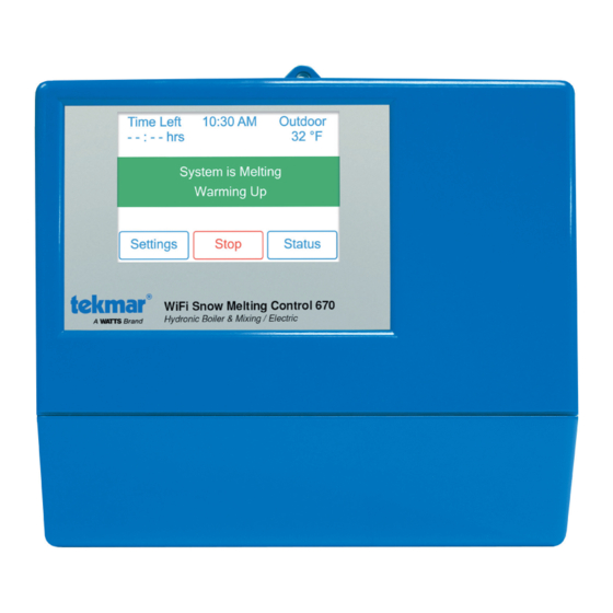
User Interface Home Screen Information about slab Remaining melting and outdoor conditions run time System operation information View status of sensor Go to settings menu readings and equipment. to setup control System Operation SYSTEM IS MELTING • The control has either detected snow/ice and automatically started or the control was manually started. -
Page 16: Symbols
Symbols WARNING SYMBOL The control has a error message. Press the warning symbol to determine the error code and information on how to take corrective action. Refer to the Troubleshooting section for a list of error codes. Help Screen The display includes a Help screen for each setting. The Help screen provides a description of the setting that is identical to the description found in the Installation and Operation Manual. -
Page 17: System Status Menu
System Status Menu Description Range Access MANUAL MELT INPUT When Manual Melt wiring terminal 13 is shorted to common wiring terminal 14, the control is enabled User and enters the melting operation unless prevented by warm weather shut down or cold weather Off, Enabled cut out. -
Page 18: Slab Status Screen
Slab Status Screen Description Range Access OUTDOOR – – –, Current outdoor air temperature as measured by the outdoor sensor or from the tekmarNet User system or Internet weather forecast. “– – –” is displayed when no outdoor temperature reading -67 to 149°F Installer is available. -
Page 19: Settings Menu Navigation
Settings Menu Navigation Step 1: Press the Settings button on the Home Screen. Step 2: Press one of the ten buttons. Step 3: Press up or down buttons to scroll through the list. Step 4: Press the highlighted setting name to change the setting value. 19 of 48... -
Page 20: Temp Menu
Temp Menu Description Range Access 32 to 95°F MELTING SETPOINT User (0.0 to 35.0°C) Select the desired temperature of the snow melt surface when melting. Installer Default = 36°F Conditions: Always available. (2.0°C) IDLING SETPOINT OFF, 20 to 95°F Select the desired temperature of the snow melt surface when idling. Idling preheats the slab User when the slab is dry but cold and allows faster reaction time to reach the melting temperature (-6.5 to 35.0°C) -
Page 21: Away Menu
Away Menu At Home Select at home to allow auto- matic snow melting operation. Away Select away to prevent snow melting operation and save energy. The home/away changes devices system-wide. All thermostats and controls that are grouped together as a location on the tekmar Connect mobile app will change together. -
Page 22: Wifi Menu
Before using the WiFi features of this product, you must accept the Terms of Use, as amended from time to time and available at Watts.com/terms-of-use. If you do not accept these terms, this product can still be used without WiFi features. -
Page 23: Energy Menu
Energy Menu View the snow melting system running hours in the past week. View the snow melting system running hours in the past year. 23 of 48... -
Page 24: Monitor Menu
Monitor Menu Description Range Access MELTING ENERGY User Records the amount of energy since the counter was last reset. 0 to 999999 kWh Installer Conditions: Available when Application Mode is set to Electric. MELTING HOURS User 0 to 999999 Records the number of melting hours since the counter was last reset. Installer hours Conditions: Always available. -
Page 25: Setup - System Setup Menu
Setup – System Setup Menu Description Range Access APPLICATION MODE The Application Mode selects the operation of the mechanical equipment. Application Mode “PWM Zone” operates a pump or zone valve to provide heat to the snow melting system. PWM Zone Mixing Application Mode “Mixing”... -
Page 26: Setup - Boiler Setup Menu
Setup – Boiler Setup Menu Description Range Access BOILER TYPE Mod, Select the type of boiler operated by the control. 1 Stage, Mod = Modulating boiler with an adjustable firing rate using a 0-10V (dc) or 4-20 mA signal. 2 Stage, 1 Stage = Single one-stage on/off boiler. -
Page 27: Setup - Mixing Setup Menu
Setup – Mixing Setup Menu Description Range Access MIXING TYPE Select the mixing output type. Floating, Floating = Floating action mixing output to operate a mixing valve. Injection, Injection = Injection mixing output to operate a wet-rotor, impedance protected pump with a current 0-10 V, Installer less than 2.4 A. -
Page 28: Tekmarnet Menu
tekmarNet Menu Description Range Access Auto, ADDRESSING b:01 to b:24, The tekmarNet address of this control. Select between automatic and manual addressing. Installer 1:01 to 1:24, To manually set the address, use the up or down buttons. 2:01 to 2:24, Conditions: Available when the 670 is connected to other controls using tekmarNet communication. -
Page 29: Toolbox Menu
Toolbox Menu Description Range Access ERROR CODE User See Error Code The current error code is displayed. Section Installer Conditions: Always available. ACCESS LEVEL User User or Installer Select the access level of the control. This determines which menus and items are available through the user interface. -
Page 30: Override Menu
Override Menu Description Range Access MANUAL OVERRIDE Manually override the normal automatic operation of the control to test the equipment or operate Auto, the system at the maximum temperature limits. Hand, Auto = Normal operation. User Max Heat, Hand = Manual override of each relay output. Test, Installer Max Heat = Operate hydronic system at maximum heat. -
Page 31: Watts ® Home App
Watts Home App ® To view and adjust the WiFi Snow Melting Control 670 using a mobile phone or tablet, download the Watts Home mobile app from the Apple iTunes Store or from the Google Play Store. ® ® ®... -
Page 32: Using The App
Using the App Settings Locations Toggle to toggle-o Away to save energy when you are away for a day or more Swipe left or long hold to Press Bars for settings edit or remove location Devices Control Current system operation status Select between Off and Melt operation Swipe left or long hold to... -
Page 33: Sequence Of Operation
Sequence of Operation Snow Melting Overview A snow melting system can offer a safe, convenient, and cost Storm Temporarily preheats the slab just below freezing to effective way of removing snow and ice from the snow melting shorten the time required to melt snow. Default is off. slab and similar surfaces. -
Page 34: Melt - Economelt
Melt EconoMelt – When a Snow/Ice Sensor 090 or 094 is installed, the installer Push Melt Button can choose to select to either automatically or manually start Mobile App Melt Button the snow melting system. Selecting EconoMelt to On allows Gateway 482 or 485 Melt Message snow removal using a snow plow or shovel. -
Page 35: Tandem Snow/Ice Detection
Tandem Snow/Ice Detection The 670 can be paired together with a 654 to allow two Snow/ Ice sensors 090 or 094 or Snow Sensors 095 to be installed for a single zone. This provides full redundancy and increases the snow detection area. Both sensors are used to detect snow or ice and if either sensor is wet the snow melting zone starts melting. -
Page 36: Idle Operation
Idle Operation When the snow melting system starts from a cold temperature, These types of systems may also use Idling but usually set there may be a long time delay before the slab is warm enough at a temperature several degrees below freezing to reduce to melt snow. -
Page 37: Slab Protection
Slab Temperature Control Controlling the slab temperature is critical to minimizing the the Status menu displays the actual measured temperature, cost of snow melting. This requires that either a Snow/Ice so it is normal to view slab temperatures that exceed the melt, Sensor 090 or 094 or a Slab Sensor 072 or 073 is installed. - Page 38 Hydronic Priority Levels -- ---------- --------- ---------------- ---------------------- --------------------- -- ---------- --------- ---------------- ---------------------- --------------------- Priority = None MELT All zones have the same priority and can operate at the same time. Zone 1 This setting is recommended when the boiler plant capacity is sized larger than the heat loss of all zones at design conditions.
-
Page 39: Warm Weather Shut Down
Warm Weather Shut Down Manual WWSD During warm weather, the slab is warm enough to naturally melt snow or ice. The control has a Warm Weather Shut Down The control enters WWSD when the outdoor air temperature (WWSD) setting in the Temperatures menu that prevents the exceeds the WWSD setting by 1°F (0.5°C) and when the control from entering Melt, Idle or Storm operation in order to slab temperature exceeds 34°F (1°C). -
Page 40: Application Modes
Application Modes The snow melting control can operate either an electric or • PWM Zone Pulse Width Modulation Zone Operation a hydronic snow melting system. A hydronic system can be • Boiler Boiler Operation categorized as boiler, mixing, boiler and mixing, or pulse •... -
Page 41: Boiler Operation
Boiler Operation The Application Mode should be set to Boiler when the snow EMS ------ ---------------------- ----------------- ------ ---------------------- ----------------- melting system has a dedicated boiler or heat source and there When the boiler is required to operate, the control's boiler is no mixing device. -
Page 42: Mixing Operation
Mixing Operation The Application Mode should be set to Mixing when a mixing • Heat relay — closes when the mixing valve is open or the valve or a mixing injection pump is installed with a shared variable speed injection pump is operating. boiler plant. -
Page 43: Troubleshooting
Troubleshooting It is recommended to complete all wiring to ensure trouble free operation. Should an error occur, simply follow these steps: 1. Find: If the control shows the Warning Symbol on the screen, it is indicating a problem on the system. 2. -
Page 44: Error Messages (2 Of 4)
Error Messages (2 of 4) Description MIX SUPPLY SENSOR OPEN CIRCUIT ERROR Due to an open circuit, the control is unable to read the Mix Supply Sensor 082 on terminals 15 and 16. The control stops operation and does not provide any heat. Check the system supply sensor wire for open circuits according to the sensor installation manual. -
Page 45: Error Messages (3 Of 4)
Error Messages (3 of 4) Description SNOW SENSOR BROWN WIRE OPEN CIRCUIT ERROR Due to an open circuit, the control is unable to read the brown wire connected to the Snow/Ice Sensor 090 or 094 on terminals 7 and 10. Idling and Storm is disabled and energy saving features such as Warm Weather Shut Down (WWSD) and Cold Weather Cut Off (CWCO) are operated using the outdoor temperature only. -
Page 46: Frequently Asked Questions
May need to move the control or router a few inches in any direction. to WiFi strength WARNING: This product contains chemicals known to the State of California to cause cancer and birth defects or other reproductive harm. For more information: Watts.com/prop65 46 of 48... -
Page 47: Technical Data
Technical Data WiFi Snow Melting Control 670 Boiler & Mixing / Electric Literature 670_A, 670_C, 670_D, 670_J, 670_U Control Microprocessor control. This is not a safety (limit) control. Packaged weight 4.3 lb. (1960 g) Dimensions 6-5/8" H x 7-9/16" W x 2-13/16" D (170 x 193 x 72 mm) Display 3.5", color touchscreen Enclosure... -
Page 48: Limited Warranty And Product Return Procedure
Limited Warranty and Product Return Procedure Limited Warranty The liability of tekmar under this warranty is limited. The tekmar harmless from and against any and all claims, liabilities and damages of any Purchaser, by taking receipt of any tekmar product (“Product”), acknowl- kind or nature which arise out of or are related to any such representations or war- edges the terms of the Limited Warranty in effect at the time of such Product ranties by Purchaser to its customers.
Need help?
Do you have a question about the Tekmar WiFi Snow Melting Control 670 and is the answer not in the manual?
Questions and answers