
Subscribe to Our Youtube Channel
Related Manuals for Optika OPTIStar OS-SZ1


Summary of Contents for Optika OPTIStar OS-SZ1
- Page 1 OPTISTAR By OPTIKA Series INSTRUCTION MANUAL Model OS-SZ1 OS-SZ2 OS-SZ3 OS-SZ4 OS-SZ5 OS-SZ6 Ver. 1.0 2021...
-
Page 2: Table Of Contents
Table of contents Warning Safety Information Unpacking Intended use Symbols and conventions Instrument description OS-SZ1 / OS-SZ2 OS-SZ3 / OS-SZ4 OS-SZ5 / OS-SZ6 Ringlight Illuminator Assembling OS-SZ1 / OS-SZ2 7.1.1 Installing focus system 7.1.2 Connecting incident light cable 7.1.3 Installing the head 7.1.4 Installing the eyepieces 7.1.5... -
Page 3: Warning
Warning This microscope is a scientific precision instrument designed to last for many years with a minimum of maintenance. It is built to high optical and mechanical standards and to withstand daily use. We remind you that this manual contains important information on safety and maintenance, and that it must therefore be made accessible to the instrument users. -
Page 4: Instrument Description
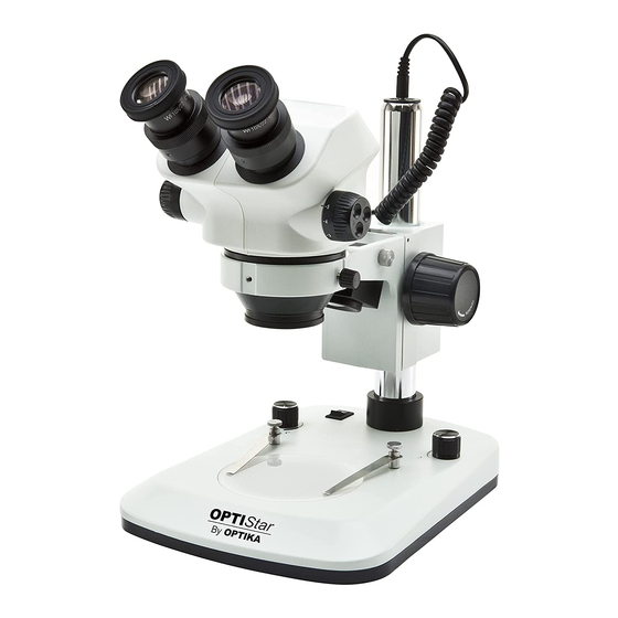
Instrument description OS-SZ1 / OS-SZ2 PHOTO/TV PORT (ONLY OS-SZ2) EYEPIECE ZOOM KNOB DIOPTER COMPENSATION RING FOCUS KNOB MICROSCOPE BODY • OS-SZ1: BINOCULAR INCIDENT LIGHT • OS-SZ2: TRINOCULAR LED ILLUMINATOR ON/OFF SWITCH TRANSMITTED LIGHT ON/OFF - INTENSITY CONTROL KNOB INCIDENT LIGHT ON/OFF - INTENSITY CONTROL KNOB STAGE CLIPS... -
Page 5: Os-Sz5 / Os-Sz6
OS-SZ5 / OS-SZ6 PILLAR HORIZONTAL PHOTO/TV PORT ARM FIXING (ONLY OS-SZ6) DIOPTER KNOB HORIZONTAL COMPENSATION FIXING KNOB FOR RING TILTING HOLDING EYEPIECE PILLAR FIXING KNOB MICROSCOPE BODY • OS-SZ5: BINOCULAR • OS-SZ6: TRINOCULAR DROP PREVENTION RING ZOOM KNOB RINGLIGHT LED ILLUMINATOR FOCUS KNOB BASE... -
Page 6: Assembling
Assembling OS-SZ1 / OS-SZ2 7.1.1 Installing focus system Place the focusing system on the pillar and, once the desired height is reached, tighten the locking knob ① located on the back of the focusing system. (Fig. 1) ① F ig. 1 ig. -
Page 7: Installing The Phototube (Only Trinocular Model)
7.1.5 Installing the phototube (only OS-SZ2) 1. Remove the dust cover by unlocking the fixing screw ①. (Fig. 5) 2. Insert the ring of the photo port ② making sure to leave the ③ fixing screw of the photo adapter ③ facing right. 3. - Page 8 3. Insert the drop preventing ring and fix it at the desired height by screwing the fixing knob. (Fig. 9) F ig. 9 ig. 9 4. Insert the horizontal arm and secure it with the fixing screw ①. (Fig. 10-11) F ig.
- Page 9 6. Once fully inserted, tighten the fixing screw ④ (Fig. 13) ④ F ig. 13 ig. 13 7. Insert from below the focusing system, tighten the fixing screw ⑤ and re-tighten the locking knob ③ from below. (Fig. 14-15) 8. Repeat steps from 7.1.3 to 7.1.5 for the installation of the head.
-
Page 10: Os-Sz5 / Os-Sz6
OS-SZ5 / OS-SZ6 1. Screw the pillar on the base. (Fig. 16) F ig. 16 ig. 16 2. Tighten the screw to lock the pillar. (Fig. 17) F ig. 17 ig. 17 3. Insert the drop preventing ring and fix it at the desired height by screwing the fixing knob. - Page 11 5. For a bigger safety, lock the fixing screw ② with the provided ② Allen wrench. (Fig. 20) F ig. 20 ig. 20 6. Install the head holder. Unscrew the prevention knob ③ and insert the head holder from below in the pillar. Lock the fixing knob ④.At the end screw again the prevention knob ③.
-
Page 12: Installing Ringlight Illuminator (Os-Sz3 / Os-Sz6)
Installing Ringlight illuminator (OS-SZ3 / OS-SZ6) 1. Screw the fixing ring ① on the bottom of the Stereo head. (Fig. 23) ① F ig. 23 ig. 23 2. Place the illuminator on the fixing ring, using the three lock- ing screws ②. (Fig. 24) ②... -
Page 13: Use Of The Microscope
Use of the microscope Adjusting interpupillary distance 1. Hold the right and left eyepiece tube with both hands and ad- just the interpupillary distance by moving the two parts until one circle of light can be seen. (Fig. 26) • If two circles appear, the interpupillary distance is too big, and if two overlapped circles appear, the interpupillary dis- tance is too small. -
Page 14: Magnification
4. Adjust the diopter compensation ring of the right eyepiece ⑥ (Fig. 30) until the image of the right eyepiece is clear and sharp. Repeat the procedure for the left eyepiece. 5. Check the focus of the image for the whole zoom range. It should be perfectly parfocal (focus is maintained during the change of magnification). -
Page 15: Black/White Stage Plate (Os-Sz1 / Os-Sz2)
Black/white stage plate (OS-SZ1 / OS-SZ2) • You can use a black/white contrast disc to increase the contrast of the image when working in incident light. (Fig. 33) 1. If you are looking at bright samples, place the disc with the black part facing up. -
Page 16: Use Of Overhanging Stand
Use of overhanging stand 8.9.1 OS-SZ3 / OS-SZ4 Moving the horizontal arm 1. Unlock the knob on the right side of the horizontal arm ①. (Fig. 35) ① F ig. 35 ig. 35 2. The arm can be extended or shortened according to specific needs. -
Page 17: Os-Sz5 / Os-Sz6
8.9.2 OS-SZ5 / OS-SZ6 Moving the horizontal arm 1. Unlock the knob on the left side of the horizontal arm ①. (Fig. F ig. 39 ig. 39 ① 2. The arm can be extended or shortened according to specific needs. (Fig. 40) F ig. -
Page 18: 8.10 Use Of Ringlight Illuminator
F ig. 43 ig. 43 Rotating the horizontal arm 1. Loosen the horizontal arm fixing knob ④ and rotate the arm, then tighten again the knob. (Fig. 44) • NOTE: 180° rotation of the microscope with respect to the base could cause a rollover of the entire system. ④... -
Page 19: Microphotography
Microphotography • Refer to specific camera Instruction manual for detailed explanation about microphotography procedure. • Instruction manual can be downloaded from this link: https://www.optikamicroscopes.com/optikamicroscopes/down- load/optistar-by-optika-digital-cameras/ Page 19... -
Page 20: Maintenance
Maintenance Microscopy environment This microscope is recommended to be used in a clean, dry and shock free environment with a temperature of 5°-40°C and a maximum relative humidity of 75 % (non condensing). Use a dehumidifier if needed. To think about when and after using the microscope •... -
Page 21: 11. Troubleshooting
11. Troubleshooting Review the information in the table below to troubleshoot operating problems. PROBLEM CAUSE SOLUTION I. Optical Section: The illumination is ON, but the field of The plug is not connected to the illu- Connect the cable view is dark. mination The brightness is too low Adjust to a proper setting... -
Page 22: Equipment Disposal
Equipment disposal Art.13 Dlsg 25 July 2005 N°151. “According to directives 2002/95/EC, 2002/96/EC and 2003/108/EC relating to the reduc- tion in the use of hazardous substances in electrical and electronic equipment and waste disposal.” The basket symbol on equipment or on its box indicates that the product at the end of its useful life should be collected sep- arately from other waste. - Page 24 Serie OPTISTAR di OPTIKA MANUALE DI ISTRUZIONI Modello OS-SZ1 OS-SZ2 OS-SZ3 OS-SZ4 OS-SZ5 OS-SZ6 Ver. 1.0 2021...
- Page 25 Sommario Avvertenza Informazioni sulla sicurezza Disimballaggio Uso previsto Simboli Descrizione dello strumento OS-SZ1 / OS-SZ2 OS-SZ3 / OS-SZ4 OS-SZ5 / OS-SZ6 lluminatore Anulare Assemblaggio OS-SZ1 / OS-SZ-2 7.1.1 Installare il sistema di messa a fuoco 7.1.2 Connettere il cavo della luce incidente 7.1.3 Installare la testa 7.1.4...
-
Page 26: Avvertenza
Avvertenza Questo microscopio è uno strumento scientifico di alta precisione, progettato per durare a lungo con una minima manutenzione; la realizzazione è secondo i migliori standard ottici e meccanici, per poter essere utilizzato quotidianamente. Vi ricordiamo che questo manuale contiene informazioni importanti per la sicurezza e per la manutenzione dello strumento, e deve quindi essere messo a disposizione di coloro che lo utilizzeranno. -
Page 27: Descrizione Dello Strumento
Descrizione dello strumento OS-SZ1 / OS-SZ2 USCITA FOTO (SOLO OS-SZ2) OCULARE SELETTORE ZOOM ANELLO COMPENSAZIONE MESSA A DIOTTRICA FUOCO CORPO MICROSCOPIO • OS-SZ1: BINOCULARE ILLUMINATORE LED • OS-SZ2: TRINOCULARE LUCE INCIDENTE INTERRUTTORE MANOPOLA ON/OFF E REGOLAZIONE INTENSITÀ MANOPOLA ON/OFF E LUCE TRASMESSA REGOLAZIONE INTENSITÀ... -
Page 28: Os-Sz5 / Os-Sz6
OS-SZ5 / OS-SZ6 USCITA FOTO MANOPOLA DI (SOLO OS-SZ6) COLONNA FISSAGGIO BRACCIO MANOPOLA DI BRACCIO ANELLO ORIZZONTALE FISSAGGIO ORIZZONTALE COMPENSAZIONE INCLINAZIONE DIOTTRICA BRACCIO DI OCULARE SUPPORTO MANOPOLA DI FISSAGGIO COLONNA CORPO MICROSCOPIO • OS-SZ5: BINOCULARE • OS-SZ6: TRINOCULARE ANELLO DI PREVENZIONE DISCESA SELETTORE... -
Page 29: Os-Sz1 / Os
Assemblaggio OS-SZ1 / OS-SZ-2 7.1.1 Installare il sistema di messa a fuoco Inserire il sistema di messa a fuoco sulla colonna e, una volta raggiunta l’altezza desiderata, serrare la manopola di bloccaggio ① posta nella parte posteriore del sistema di messa a fuoco. ①... -
Page 30: Installare L'uscita Foto (Solo Os-Sz2)
7.1.5 Installare l’uscita foto (solo OS-SZ2) 1. Allentare le viti di fissaggio ① dell’uscita foto in dotazione e rimuovere l’uscita foto esistente. (Fig. 5) 2. Inserire l’anello dell’uscita foto ② facendo attenzione a la- ③ sciare la vite di fissaggio dell’adattatore fotografico ③ rivolta verso destra. - Page 31 3. Inserire l’anello di prevenzione discesa e fissarlo all’altezza desiderata avvitando la manopola di fissaggio. (Fig. 9) F ig. 9 ig. 9 4. Inserire il braccio orizzontale e bloccarlo con la vite di fissag- gio ①. (Fig. 10-11) F ig. 10 ig.
- Page 32 6. Una volta inserito a fondo bloccare la vite di fissaggio ④. (Fig. 13) ④ F ig. 13 ig. 13 7. Inserire dal basso il sistema di messa a fuoco, serrare la vite di fissaggio ⑤ ed avvitare nuovamente la manopola di bloc- co ③...
-
Page 33: Os-Sz5 / Os-Sz6
OS-SZ5 / OS-SZ6 1. Avvitare la colonna alla base. (Fig. 16) F ig. 16 ig. 16 2. Avvitare le viti per bloccare la colonna. (Fig. 17) F ig. 17 ig. 17 3. Inserire l’anello di prevenzione discesa e fissarlo all’altezza desiderata avvitando la manopola di fissaggio. - Page 34 5. Per una maggiore sicurezza, serrare la vite di fissaggio ② ② con la brugola in dotazione. (Fig. 20) F ig. 20 ig. 20 6. Installare il sistema di messa a fuoco. Svitare la manopola di blocco ③ ed inserire il supporto ④ dal basso nella colonna. Al termine riavvitare la manopola di blocco ③.
-
Page 35: Installare L'illuminatore Anulare (Os-Sz3 / Os-Sz6)
Installare l’illuminatore Anulare (OS-SZ3 / OS-SZ6) 1. Avvitare l’anello di fissaggio ① nella parte inferiore della te- sta stereo. (Fig. 23) ① F ig. 23 ig. 23 2. Posizionare l’illuminatore sull’anello di fissaggio, usando le tre viti di bloccaggio ②. (Fig. 24) ②... -
Page 36: Uso Del Microscopio
Uso del microscopio Regolazione della distanza interpupillare 1. Afferrare con entrambe le mani i portaoculari destro e sinistro e regolare la distanza interpupillare spostando i tubi fino a che si osserva una sola immagine (Fig. 26). • Se si osservano due immagini la distanza è troppo elevata. •... -
Page 37: Ingrandimento
4. Regolare l’anello di regolazione diottrica dell’oculare destro ⑥ (Fig. 30) fino a che l’immagine è a fuoco. Ripetere la pro- cedura per l’oculare sinistro. 5. Ora verificare la messa a fuoco del campione lungo l’intero range di zoom. Il sistema ora è perfettamente parafocale (il fuoco è... -
Page 38: Piattello Bianco/Nero (Os-Sz1 / Os-Sz2)
Piattello bianco/nero (OS-SZ1 / OS-SZ2) • È possibile usare un disco di contrasto banco/nero per au- mentare il contrasto dell’immagine quando si lavora in luce incidente. (Fig. 33) 1. Se si osservano campioni chiari, posizionare il disco con la parte nera rivolta verso l’alto. 2. -
Page 39: Uso Delle Basi A Sbalzo
Uso delle basi a sbalzo 8.9.1 OS-SZ3 / OS-SZ4 Spostare il braccio orizzontale 1. Allentare le manopole sulla parte destra del braccio orizzontale ①. (Fig. 35) ① F ig. 35 ig. 35 2. Il braccio può essere allungato o accorciato in base alle specifiche esigenze. -
Page 40: Os-Sz5 / Os-Sz6
8.9.2 OS-SZ5 / OS-SZ6 Spostare il braccio orizzontale 1. Allentare la manopola sulla parte sinistra del braccio orizzontale ①. (Fig. 39) F ig. 39 ig. 39 ① 2. Il braccio può essere allungato o accorciato in base alle specifiche esigenze. (Fig. 40) F ig. -
Page 41: 8.10 Uso Dell'illuminatore Anulare
F ig. 43 ig. 43 Ruotare il braccio orizzontale 1. Allentare la vite di fissaggio del braccio orizzontale ④ e ruotare il braccio, quindi serrare la vite di fissaggio. (Fig. 44) • NOTA: Una rotazione del microscopio di 180° rispetto alla base potrebbe causare un rovesciamento di tutto il sistema. -
Page 42: Microfotografia
Microfotografia • Consultare il manuale d’istruzioni specifico della fotocamera per una spiegazione dettagliata della procedura di micro- fotografia. • Il manuale di istruzioni può essere scaricato da questo link: https://www.optikamicroscopes.com/optikamicroscopes/ download/optistar-by-optika-digital-cameras/ Pagina 42... -
Page 43: 10. Manutenzione
10. Manutenzione Ambiente di lavoro Si consiglia di utilizzare il microscopio in un ambiente pulito e secco, privo di urti, ad una temperatura fra 0°C e 40°C e con una umidità relativa massima dell’85% (in assenza di condensazione). Si consiglia l’uso di un deumidificatore se necessario. Prima e dopo l’utilizzo del microscopio •... -
Page 44: 11. Guida Alla Risoluzione Dei Problemi
11. Guida alla risoluzione dei problemi Consultare le informazioni riportate nella tabella seguente per risolvere eventuali problemi operativi. PROBLEMA CAUSA SOLUZIONE I. Sezione Ottica: Il LED è acceso, ma il campo visivo è L’alimentatore è scollegato. Collegarlo scuro La luminosità è troppo bassa Regolarla ad un livello adeguato I bordi del campo visivo sono vignettati L’illuminatore per luce incidente non è... -
Page 45: Smaltimento
Smaltimento Ai sensi dell’articolo 13 del decreto legislativo 25 luglio 2005 n°151. “Attuazione delle direttive 2002/95/CE, 2002/96/CE e 2003/108/CE, relative alla riduzione dell’uso di sostanze pericolose nelle apparecchiature elettriche ed elettroniche, nonché allo smaltimento dei rifiuti”. Il simbolo del cassonetto riportato sulla apparecchiatura o sulla sua confezione indica che il prodotto alla fine della propria vita utile deve essere raccolto separatamente degli altri rifiuti. - Page 47 Serie OPTISTAR de OPTIKA MANUAL DE INSTRUCCIONES Modelo OS-SZ1 OS-SZ2 OS-SZ3 OS-SZ4 OS-SZ5 OS-SZ6 Ver. 1.0 2021...
- Page 48 Índice Advertencia Información de seguridad Desembalaje Utilización Símbolos Descripción del instrumento OS-SZ1 / OS-SZ2 OS-SZ3 / OS-SZ4 OS-SZ5 / OS-SZ6 Illuminador Anular Montaje OS-SZ1 / OS-SZ-2 7.1.1 Instalar el sistema de enfoque 7.1.2 Conexión del cable de luz incidente 7.1.3 Instalar el cabezal 7.1.4 Inserción de oculares...
-
Page 49: Advertencia
Advertencia Este microscopio es un instrumento científico de precisión. Su utilización está pensada para una larga duración con un mínimo nivel de mantenimiento. Para su fabricación se han utilizado elementos ópticos y mecánicos de elevada calidad que lo convierten en el instrumento ideal para la utilización diaria en las aulas y el laboratorio. Informamos que esta guía contiene importantes informaciones sobre la seguridad y el mantenimiento del producto y por lo tanto debe ser accesible a todos aquellos que utilizan dicho instrumento. -
Page 50: Descripción Del Instrumento
Descripción del instrumento OS-SZ1 / OS-SZ2 PUERTO DE FOTO/ TV (SÓLO OS-SZ2) OCULAR MANDO ZOOM ANILLO DE COMPENSACIÓN MANDO DE DIÓPTRICA ENFOQUE CUERPO MICROSCOPIO • OS-SZ1: BINOCULAR ILUMINADOR LED • OS-SZ2: TRINOCULAR LUZ INCIDENTE INTERRUPTOR BOTÓN ON/OFF - BOTÓN ON/OFF - CONTROL CONTROL DE INTENSIDAD DE LA... -
Page 51: Os-Sz5 / Os-Sz6
OS-SZ5 / OS-SZ6 PUERTO DE FOTO/ POMO DE TV (SÓLO OS-SZ6) PILAR FIJACIÓN DE BRAZO POMO DE BRAZO ANILLO DE HORIZONTAL FIJACIÓN PARA HORIZONTAL COMPENSACIÓN LA INCLINACIÓN DIÓPTRICA DEL BRAZO DE SOPORTE OCULAR POMO DE FIJACIÓN PILAR CUERPO MICROSCOPIO • OS-SZ5: BINOCULAR •... -
Page 52: Montaje
Montaje OS-SZ1 / OS-SZ-2 7.1.1 Instalar el sistema de enfoque Coloque el sistema de enfoque en la columna y, una vez alcan- zada la altura deseada, apriete la perilla de bloqueo ① situada en la parte posterior del sistema de enfoque. (Fig. 1) ①... -
Page 53: Instalar La Salida De Fotos (Sólo Os-Sz2)
7.1.5 Instalar la salida de fotos (sólo OS-SZ2) 1. Afloje los tornillos de fijación ① de la salida de foto suminis- trada y retire la salida de foto existente. (Fig. 5) ③ 2. Inserte el anillo de la salida de foto ② asegurándose de dejar el tornillo de fijación del adaptador de foto ③... - Page 54 3. Inserte el anillo de prevención de caídas y fíjelo a la altura deseada atornillando el pomo de fijación. (Fig. 9) F ig. 9 ig. 9 4. Insertar el brazo horizontal y fijarlo con el tornillo de fijación ①. (Fig. 10-11) F ig.
- Page 55 6. Una vez insertado completamente, apriete el tornillo de fija- ción ④ (Fig. 13) ④ F ig. 13 ig. 13 7. Inserte el sistema de enfoque desde abajo, apriete el tornillo de fijación ⑤ y vuelva a apretar la perilla de bloqueo ③ des- de abajo.
- Page 56 OS-SZ5 / OS-SZ6 1. Atornille el pilar a la base. (Fig. 16) F ig. 16 ig. 16 2. Apriete los tornillos para bloquear el pilar. (Fig. 17) F ig. 17 ig. 17 3. Inserte el anillo de prevención de caídas y fíjelo a la altura deseada atornillando el pomo de fijación.
- Page 57 5. Para mayor seguridad, fije el tornillo de fijación ② con la lla- ② ve Allen suministrada. (Fig. 20) F ig. 20 ig. 20 6. Instale el soporte del cabezal. Desenrosque el botón de pre- vención ③ e inserte el reposacabezas desde abajo en el bra- zo vertical.
-
Page 58: Instalación Del Iluminador Anular (Os-Sz3 / Os-Sz6)
Instalación del iluminador Anular (OS-SZ3 / OS-SZ6) 1. Atornille el anillo de fijación ① en la parte inferior del cabe- zal. (Fig. 23) ① F ig. 23 ig. 23 2. Coloque el iluminador en el anillo de fijación, utilizando los tres tornillos de bloqueo ②. -
Page 59: Uso Del Microscopio
Uso del microscopio Regulación de la distancia interpupilar 1. Sujete los portaoculares izquierdo y derecho con ambas ma- nos y ajuste la distancia interpupilar moviendo los tubos has- ta que sólo se observe una imagen. (Fig. 26) • Si miras dos imágenes, la distancia es demasiado grande. •... -
Page 60: Aumento
4. Ajuste el anillo de compensación de dioptrías del ocular de- recho ⑥ (Fig. 30) hasta que la imagen del ocular derecho sea clara y nítida. Repita el procedimiento para el ocular iz- quierdo. 5. A continuación, compruebe el enfoque de la imagen para todo el rango de zoom. -
Page 61: Placa Blanco/Negro (Os-Sz1 / Os-Sz2)
Placa blanco/negro (OS-SZ1 / OS-SZ2) • Puede utilizar un disco de contraste de banco/negro para aumentar el contraste de la imagen cuando trabaje con luz incidente. (Fig. 33) 1. Si se observan muestras claras, coloque el disco con la parte negra hacia arriba. -
Page 62: Uso De Bases En Voladizo
Uso de bases en voladizo 8.9.1 OS-SZ3 / OS-SZ4 Mover el brazo horizontal 1. Afloje las perillas del lado derecho del brazo horizontal ①. (Fig. 35) ① F ig. 35 ig. 35 2. El brazo puede ser extendido o acortado de acuerdo a las necesidades específicas. - Page 63 8.9.2 OS-SZ5 / OS-SZ6 Mover el brazo horizontal 1. Afloje la perilla del lado izquierdo del brazo horizontal ①. (Fig. 39) F ig. 39 ig. 39 ① 2. El brazo puede ser extendido o acortado de acuerdo a las necesidades específica. (Fig. 40) F ig.
-
Page 64: Uso Del Iluminador Anular
F ig. 43 ig. 43 Girar el brazo horizontal 1. Afloje el tornillo de fijación del brazo horizontal ④ y gire el brazo, luego apriete el tornillo de fijación. (Fig. 44) • NOTA: Girar el microscopio 180° desde la base puede causar que todo el sistema se vuelque. -
Page 65: Microfotografía
Microfotografía • Consulte el manual de instrucciones específico de su cámara para obtener una explicación detallada del procedimiento de microfotografía. • El manual de instrucciones puede descargarse desde este enlace: https://www.optikamicroscopes.com/optikamicro- scopes/download/optistar-by-optika-digital-cameras/ Página 65... -
Page 66: Mantenimiento
10. Mantenimiento Ambiente de trabajo Se aconseja utilizar este microscopio en un ambiente limpio y seco; también se deben evitar los impactos. La temperatura de trabajo recomendada es de 0-40°C y la humedad relativa máxima es de 85 % (en ausencia de condensación). Si es necesario, utilizar un deshumidificador. -
Page 67: Guía De Solución De Problemas
11. Guía de solución de problemas Revisar la información en la tabla a continuación para solucionar problemas de funcionamiento. PROBLEMA CAUSA SOLUCIÓN I. Sección Óptica: El iluminador está encendido, pero el El enchufe no está conectado al siste- Conectar campo visible está oscuro ma de iluminación La luminosidad es demasiado baja Regular la luminosidad... -
Page 68: Medidas Ecológicas Y Reciclaje
Medidas ecológicas y reciclaje De conformidad con el artículo 13 del Decreto Legislativo Nº 151, de 25 de julio de 2005. “Aplicación de las Directivas 2002/95/CE, 2002/96/CE y 2003/108/CE sobre la reducción del uso de sustancias peligrosas en aparatos eléctricos y elec- trónicos y la eliminación de residuos. - Page 70 Série OPTISTAR par OPTIKA MANUEL D’UTILISATION Modèle OS-SZ1 OS-SZ2 OS-SZ3 OS-SZ4 OS-SZ5 OS-SZ6 Ver. 1.0 2021...
- Page 71 Sommaire Avertissement Précautions Déballage Emploi prévu Symboles Description de l’instrument OS-SZ1 / OS-SZ2 OS-SZ3 / OS-SZ4 OS-SZ5 / OS-SZ6 Iluminateur Annulaire Assemblage OS-SZ1 / OS-SZ-2 7.1.1 Installation du système de mise au point 7.1.2 Connexion du câble de la lumière incidente 7.1.3 Installer la tête 7.1.4...
-
Page 72: Avertissement
Avertissement Le présent microscope est un appareil scientifique de précision créé pour offrir une durée de vie de plusieurs années avec un niveau d’entretien minimum. Les meilleurs composants optiques et mécaniques ont été utilisés pour sa conception ce qui fond de lui un appareil idéal pour une utilisation journalière. Ce guide contient des informations importantes sur la sécurité... -
Page 73: Description De L'instrument
Description de l’instrument OS-SZ1 / OS-SZ2 SORTIE PHOTO/TV (SEULEMENT OS-SZ2) OCULAIRE BOUTON DE ZOOM ANNEAU DE COMPENSATION BOUTON DE DIOPTRIQUE MISE AU POINT CORPS DU MICROSCOPE • OS-SZ1: BINOCULAIRE ILLUMINATEUR LED • OS-SZ2: TRINOCULAIRE LUMIÈRE INCIDENTE INTERRUPTEUR BOUTON MARCHE/ARRÊT ET RÉGLAGE DE BOUTON MARCHE/ L’INTENSITÉ... -
Page 74: Os-Sz5 / Os-Sz6
OS-SZ5 / OS-SZ6 SORTIE PHOTO/TV BOUTON DE (SEULEMENT OS-SZ6) PILIER FIXATION DU BRAS BOUTON DE HORIZONTAL ANNEAU DE BRAS FIXATION POUR COMPENSATION HORIZONTAL L’INCLINATION DIOPTRIQUE DU BRAS DE OCULAIRE SUPPORT BOUTON DE FIXATION DU PILIER CORPS DU MICROSCOPE • OS-SZ5: BINOCULAIRE •... -
Page 75: Assemblage
Assemblage OS-SZ1 / OS-SZ-2 7.1.1 Installation du système de mise au point Placez le système de mise au point sur la colonne et, une fois la hauteur souhaitée atteinte, serrez le bouton de verrouillage ① situé à l’arrière du système de mise au point. (Fig. 1) ①... -
Page 76: Installer La Sortie Photo (Seulement Os-Sz2)
7.1.5 Installer la sortie photo (seulement OS-SZ2) 1. Desserrez les vis de fixation ① de la sortie photo fournie et retirez la sortie photo existante. (Fig. 5) 2. Insérez la bague de la sortie photo ② en veillant à laisser la ③... - Page 77 3. Insérez la bague de prévention de descente et fixez-la à la hauteur désirée en vissant le bouton de fixation. (Fig. 9) F ig. 9 ig. 9 4. Insérer le bras horizontal et le fixer à l’aide de la vis de fixa- tion ①.
- Page 78 6. Une fois complètement inséré, serrer la vis de fixation ④ (Fig. 13) ④ F ig. 13 ig. 13 7. Insérer le système de mise au point par le bas, serrer la vis de fixation ⑤ et resserrer le bouton de verrouillage ③ par le bas.
- Page 79 OS-SZ5 / OS-SZ6 1. Visser le pilier à la base. (Fig. 16) F ig. 16 ig. 16 2. Serrer les vis pour bloquer le pilier. (Fig. 17) F ig. 17 ig. 17 3. Insérez la bague de prévention de descente et fixez-la à la hauteur désirée en vissant le bouton de fixation.
- Page 80 5. Pour plus de sécurité, serrez la vis de fixation ② avec la clé ② Allen fournie ②. (Fig. 20) F ig. 20 ig. 20 6. Installez le système de mise au point. Dévisser le bouton de verrouillage ③ et insérer le support ④ par le bas dans le pilier.
-
Page 81: Installer L'illuminateur Annulaire (Os-Sz3 / Os-Sz6)
Installer l’illuminateur Annulaire (OS-SZ3 / OS-SZ6) 1. Visser l’anneau de fixation ① dans le fond de la tête. (Fig. ① F ig. 23 ig. 23 2. Positionnez l’illuminateur sur la bague de fixation, en utilisant les trois vis de blocage. ②. (Fig. 24) ②... -
Page 82: Utilisation Du Microscope
Utilisation du microscope Ajuster la distance interpupillaire 1. Tenez le tube oculaire droit et gauche avec les deux mains et réglez la distance interpupillaire en déplaçant les deux par- ties jusqu’à ce qu’un cercle lumineux soit visible. • Si deux cercles apparaissent, la distance interpupillaire est trop grande. -
Page 83: Grossissement
4. Régler la bague de compensation dioptrique de l’oculaire droit ⑥ (Fig. 30) jusqu’à ce que l’image de l’oculaire droit soit nette. Répéter la procédure pour l’oculaire gauche. 5. Ensuite, vérifiez la mise au point de l’image pour toute la plage de zoom. -
Page 84: Plaque Noir/Blanc (Os-Sz1 / Os-Sz2)
Plaque noir/blanc (OS-SZ1 / OS-SZ2) • Vous pouvez utiliser un disque de contraste noir/blanc pour augmenter le contraste de l’image lorsque vous travaillez en lumière incidente. (Fig. 33) 1. Si vous regardez des échantillons clairs, placez le disque avec la partie noire vers le haut. 2. -
Page 85: Utilisation D'une Base En Surplomb
Utilisation d’une base en surplomb 8.9.1 OS-SZ3 / OS-SZ4 Déplacer le bras horizontal 1. Desserrez les boutons du côté droit du bras horizontal ①. (Fig. 35) ① F ig. 35 ig. 35 2. Le bras peut être allongé ou raccourci selon les besoins spécifiques. - Page 86 8.9.2 OS-SZ5 / OS-SZ6 Déplacer le bras horizontal 1. Desserrez le bouton sur le côté gauche du bras horizontal ①. (Fig. 39) F ig. 39 ig. 39 ① 2. Le bras peut être allongé ou raccourci selon les besoins spécifiques. (Fig. 40) F ig.
-
Page 87: 8.10 Utilisation De L'illuminateur Annulaire
F ig. 43 ig. 43 Tourner le bras horizontal 1. Desserrer la vis de fixation du bras horizontal ④ et tourner le bras, puis serrer la vis de fixation. (Fig. 44) • REMARQUE : Une rotation du microscope de 180° par rapport à... -
Page 88: Microphotographie
Microphotographie • Veuillez vous référer au manuel d’instructions de votre appareil photo spécifique pour une explication détaillée de la procédure de microphotographie. de microfotografía. • Le manuel d’instruction peut être téléchargé à partir de ce lien: https://www.optikamicroscopes.com/optikamicroscopes/ download/optistar-by-optika-digital-cameras/ Page 88... -
Page 89: 10. Réparation Et Entretien
10. Réparation et entretien Environnement de travail Il est conseillé d’utiliser le microscope dans un environnement propre et sec, protégé des impactes, à une température comprise entre 0°C y 40°C et avec une humidité relative maximale de 85% (en absence de condensation). Il est conseillé d’utiliser un déshumidificateur si nécessaire. -
Page 90: 11. Guide Résolution Des Problèmes
11. Guide résolution des problèmes Passer en revue les informations dans le tableau ci-dessous pour résoudre les problèmes opérationnels. PROBLÈME CAUSE SOLUTION I. Section Optique: La lampe est allumée mais le champ Les câbles d’alimentation ne sont Brancher les correctement visuel est sombre. -
Page 91: Ramassage
Ramassage Conformément à l’Article 13 du D.L du 25 Juillet 2005 nº151 Action des Directives 2002/95/CE, 2002/96/CE et 2003/108/CE, relatives à la réduction de l’utilisation de substances dan- gereuses dans l’appareil électrique et électronique et à l’élimination des résidus. Le Symbole du conteneur qui figure sur l’appareil électrique ou sur son emballage indique que le produit devra être, à la fin de sa vie utile, séparé... - Page 93 OPTISTAR-Serie von OPTIKA BEDIENUNGSANLEITUNG Modell OS-SZ1 OS-SZ2 OS-SZ3 OS-SZ4 OS-SZ5 OS-SZ6 Ver. 1.0 2021...
- Page 94 Inhalt Hinweis Sicherheitsinformationen Verwendung Wartung- und Gefahrzeichen Beschreibung des Instruments OS-SZ1 / OS-SZ2 OS-SZ3 / OS-SZ4 OS-SZ5 / OS-SZ6 Ringlicht Beleuchter Montage OS-SZ1 / OS-SZ2 7.1.1 Installation des Fokussystems 7.1.2 Anschluss des Auflichtkabels 7.1.3 Montage des Kopfes 7.1.4 Okulare montieren 7.1.5 Montage des Fototubus (nur OS-SZ2) 7.1.6 Anschluss des Netzteils OS-SZ3 / OS-SZ4...
-
Page 95: Hinweis
Hinweis Dieses Mikroskop ist ein wissenschaftliches Präzisionsgerät, es wurde entwickelt für eine jahrelange Verwendung bei einer minimalen Wartung. Dieses Gerät wurde nach den höchsten optischen und mechanischen Standards und zum täglichen Gebrauch hergestellt. Diese Bedienungsanleitung enthält wichtige Informationen zur korrekten und sicheren Benutzung des Geräts. -
Page 96: Beschreibung Des Instruments
Beschreibung des Instruments OS-SZ1 / OS-SZ2 FOTO/TV AUSGANG (NUR OS-SZ2) OKULARE ZOOMSCHALTER DIOPTRISCHER KOMPENSATIONSRING FOKUSSIERKNOPF KÖRPERMIKROSKOP • OS-SZ1: BINOKULAR AUFLICHT LED • OS-SZ2: TRINOKULAR BELEUCHTUNG EIN/AUS- SCHALTER EIN/AUS-KNOPF UND DURCHLICHTREGELUNG EIN/AUS-KNOPF UND AUFLICHTREGELUNG MUSTER-CLIPS DURCHLICHT BELEUCHTUNG BASE OS-SZ3 / OS-SZ4 STÜTZE HORIZONTALER HORIZONTALER ARM... -
Page 97: Os-Sz5 / Os-Sz6
OS-SZ5 / OS-SZ6 STÜTZE FOTO/TV AUSGANG HORIZONTALER ARM (NUR OS-SZ6) DIOPTRISCHER FIXIERKNÖPFE HORIZONTALER KOMPENSA- BEFESTIGUNGSKNOPF TIONSRING FÜR DIE NEIGUNG DES TRAGARMS OKULARE STÜTZE FIXIERKNÖPFE KÖRPERMIKROSKOP • OS-SZ5: BINOKULAR ABSTURZSICHE- • OS-SZ6: TRINOKULAR RUNGSRING ZOOMSCHALTER RINGLICHT LED BELEUCHTER FOKUSSIERKNOPF BASE Ringlicht Beleuchter FIXIERRING SCHRAUBEN- SCHLÜSSE... -
Page 98: Montage
Montage OS-SZ1 / OS-SZ2 7.1.1 Installation des Fokussystems Stellen Sie das Fokussiersystem auf die Stütze und ziehen Sie, sobald die gewünschte Höhe erreicht ist, den Verriegelungs- knopf ① auf der Rückseite des Fokussiersystems fest. (Fig. 1) ① F ig. 1 ig. -
Page 99: Montage Des Fototubus (Nur Os-Sz2)
7.1.5 Montage des Fototubus (nur OS-SZ2) 1. Lösen Sie die Befestigungsschrauben ① des mitgelieferten Foto-Ausgangs und entfernen Sie den vorhandenen Foto- Ausgang. (Fig. 5) ③ 2. Setzen Sie den Ring des Fotoausgangs ② ein und achten Sie darauf, dass die Befestigungsschraube des Fotoadap- ters ③... - Page 100 3. Setzen Sie den Absturzsicherungsring ein und befestigen Sie ihn in der gewünschten Höhe durch Aufschrauben des Befestigungsknopfes. (Fig. 9) F ig. 9 ig. 9 4. Setzen Sie den Horizontalarm ein und sichern Sie ihn mit der Befestigungsschraube ①. (Fig. 10-11) F ig.
- Page 101 6. Nach dem vollständigen Einsetzen die Befestigungsschrau- be ④ sichern. (Fig. 13) ④ F ig. 13 ig. 13 7. Setzen Sie das Fokussiersystem von unten ein, ziehen Sie die Befestigungsschraube ⑤ an und ziehen Sie den Verrie- gelungsknopf ③ von unten wieder an. (Fig. 14-15) 8.
-
Page 102: Os-Sz5 / Os-Sz6
OS-SZ5 / OS-SZ6 1. Schrauben Sie die Stütze an den Sockel. (Fig. 16) F ig. 16 ig. 16 2. Ziehen Sie die Schrauben an, um die Stütze zu sichern. (Fig. F ig. 17 ig. 17 3. Setzen Sie den Absturzsicherungsring ein und befestigen Sie ihn in der gewünschten Höhe durch Aufschrauben des Befestigungsknopfes. - Page 103 5. Zur zusätzlichen Sicherheit ziehen Sie die Befestigungs- ② schraube ② mit dem mitgelieferten Inbusschlüssel an. (Fig. F ig. 20 ig. 20 6. Installieren Sie das Fokussiersystem. Lösen Sie den Verrie- gelungsknopf ③ und setzen Sie die Halterung ④ von un- ten in den Vertikalarm ein.
-
Page 104: Montage Der Ringlicht-Beleuchtung (Os-Sz3 / Os-Sz6)
Montage der Ringlicht-Beleuchtung (OS-SZ3 / OS- SZ6) 1. Schrauben Sie den Befestigungsring ① auf die Unterseite des Stereokopfes. (Fig. 23) ① F ig. 23 ig. 23 2. Setzen Sie den Illuminator mit den drei Feststellschrauben auf den Befestigungsring ②. (Fig. 24) ②... -
Page 105: Verwendung Des Mikroskops
Verwendung des mikroskops Einstellen des Augenabstandes 1. Halten Sie den linken und rechten Okularhalter mit beiden Händen und stellen Sie den Augenabstand durch Bewegen der Röhren ein, bis nur noch ein Bild zu sehen ist. (Fig. 26). • Wenn man sich zwei Bilder ansieht, ist der Abstand zu groß. •... -
Page 106: Vergrößerung
4. Stellen Sie den dioptrischen Einstellring des rechten Okulars ⑥ so ein, dass das betrachtete Bild scharf und fokussiert ist (Fig. 30). Wiederholen Sie den Vorgang mit dem linken Okularring. 5. Überprüfen Sie nun den Fokus des Samples über den ge- samten Zoombereich. -
Page 107: Schwarz/Weiß Platte (Os-Sz1 / Os-Sz2)
Schwarz/weiß Platte (OS-SZ1 / OS-SZ2) • Sie können eine Schwarz/Weiß-Kontrastscheibe verwenden, um den Kontrast des Bildes beim Arbeiten im Auflicht zu er- höhen. (Fig. 33). 1. Wenn Sie helle Proben betrachten, legen Sie die Scheibe mit dem schwarzen Teil nach oben ein. 2. -
Page 108: Verwendung Von Kragarmstützen
Verwendung von Kragarmstützen 8.9.1 OS-SZ3 / OS-SZ4 Bewegen Sie den horizontalen Arm 1. Lösen Sie die Knöpfe auf der rechten Seite des horizontalen Arms ①. (Fig. 35) ① F ig. 35 ig. 35 2. Der Arm kann je nach Bedarf verlängert oder verkürzt werden. - Page 109 8.9.2 OS-SZ5 / OS-SZ6 Bewegen Sie den horizontalen Arm 1. Lösen Sie den Knopf auf der linken Seite des horizontalen Arms ①. (Fig. 39) F ig. 39 ig. 39 ① 2. Der Arm kann je nach Bedarf verlängert oder verkürzt werden.
-
Page 110: 8.10 Verwendung Des Ringlicht-Beleuchtung
F ig. 43 ig. 43 Drehen Sie den horizontalen Arm 1. Lösen Sie die Befestigungsschraube des Horizontalarms ④ und drehen Sie den Arm, dann ziehen Sie die Befestigungsschraube an. (Fig. 44) • HINWEIS: Wenn Sie das Mikroskop um 180° von der Basis aus drehen, kann das gesamte System umkippen. -
Page 111: Mikrofotografie
Mikrofotografie • Ausführliche Erläuterungen zum Mikrofotografieverfahren finden Sie in der Bedienungsanleitung der jeweiligen Kame- • Die Bedienungsanleitung kann über diesen Link heruntergeladen werden: https://www.optikamicroscopes.com/optika- microscopes/download/optistar-by-optika-digital-cameras/ Seite 111... -
Page 112: 10. Wartung
10. Wartung Arbeitsumfeld Es wird empfohlen, das Mikroskop an einem sauberen, trockenen und stoßsicheren Ort zu verwenden, bei einer Tempe- ratur zwischen 0° und 40° und einer Feuchtigkeit nicht über 85% (ohne Kondensation). Wenn nötig wird die Verwendung eines Luftentfeuchters empfohlen. Vor und nach dem Gebrauch des Mikroskops •... -
Page 113: 11. Probleme Und Lösungen
11. Probleme und Lösungen Lesen Sie die Informationen in der folgenden Tabelle, um Probleme bei der Bedienung zu beheben. PROBLEM URSACHE LÖSUNG I. Optisches System: Die Beleuchtung ist eingeschaltet, Stromversorgungsstecker sind nicht Verbinden Sie sie aber das Sichtfeld ist dunkel gut angeschlossen. -
Page 114: Wiederverwertung
Wiederverwertung Gemäß dem Artikel 13 vom Dekret Nr. 151 vom 25.07.2005 “Umsetzung der Richtlinien 2002/95/EG, 2002/96/EG und 2003/108/EG in Bezug auf die Verwendung gefährlicher Stoffe in elektrischen und elektronischen Geräten sowie die Ab- fallentsorgung”. Das Symbol vom Müllcontainer erscheint auf dem Gerät oder der Verpackung und weist darauf hin, dass das Produkt Ende des Lebens separat von anderen Abfällen entsorgt werden muss. - Page 116 OPTISTAR Por OPTIKA Series MANUAL DE INSTRUÇÕES Modelo OS-SZ1 OS-SZ2 OS-SZ3 OS-SZ4 OS-SZ5 OS-SZ6 Ver. 1.0 2021...
- Page 117 Tabela de Conteúdos Advertência Informações sobre a segurança Desembalando Uso previsto Simbolos Descrição do instrumento OS-SZ1 / OS-SZ2 OS-SZ3 / OS-SZ4 OS-SZ5 / OS-SZ6 Iluminador Anular Montagem OS-SZ1 / OS-SZ-2 7.1.1 Instalar o sistema de focagem 7.1.2 Ligar o cabo de luz incidente 7.1.3 Instalar a cabeça 7.1.4...
-
Page 118: Advertência
Advertência Este microscópio é um instrumento científico de alta precisão, projectado para durar um longo tempo com manutenção mínima; a sua realização respeita os melhores padrões ópticos e mecânicos, para que possa ser utilizado diariamente. Recordamos que este manual contém informações importantes para a segurança e a manutenção do instrumento, portanto deve ser colocado à... -
Page 119: Descrição Do Instrumento
Descrição do instrumento OS-SZ1 / OS-SZ2 SAÍDA DE FOTO (APENAS OS-SZ2) OCULAR VARIADOR DE AMPLIAÇÃO ANEL DE COMPENSAÇÃO BOTÃO DE DIÓPTRICA FOCAGEM CORPO DO MICROSCÓPIO • OS-SZ1: BINOCULAR ILUMINADOR LED DE • OS-SZ2: TRINOCULAR LUZ INCIDENTE INTERRUPTOR BOTÃO DE LIGAR/DESLI- GAR E CONTROLO DA BOTÃO DE LIGAR/DESLI- INTENSIDADE DA LUZ... -
Page 120: Os-Sz5 / Os-Sz6
OS-SZ5 / OS-SZ6 SAÍDA DE FOTO BOTÃO DE (APENAS OS-SZ6) PILAR FIXAÇÃO BRAÇO BRAÇO ANELLO HORIZONTAL BOTÃO DE FIXAÇÃO HORIZONTAL COMPENSAZIONE INCLINAÇÃO DIOTTRICA DO BRAÇO DE SUPORTE OCULAR BOTÃO DE FIXAÇÃO DO PILAR CORPO DO MICROSCÓPIO • OS-SZ5: BINOCULAR ANEL DE •... -
Page 121: Instalar O Sistema De Focagem
Montagem OS-SZ1 / OS-SZ-2 7.1.1 Instalar o sistema de focagem Coloque o sistema de focagem no pilar e, uma vez atingida a al- tura desejada, aperte o botão de bloqueio ① localizado na parte posterior do sistema de focagem. (Fig. 1) ①... -
Page 122: Instalar A Saída De Foto (Os-Sz2)
7.1.5 Instalar a saída de foto (OS-SZ2) 1. Desaperte os parafusos de fixação ① da saída de foto forne- cida e remova a saída de foto existente. (Fig. 5) 2. Insira o anel da saída da foto ② certificando-se de deixar o ③... - Page 123 3. Insira o anel de prevenção de descenso e fixe-o na altura desejada aparafusando o botão de fixação. (Fig. 9) F ig. 9 ig. 9 4. Inserir o braço horizontal e fixa-lo com o parafuso de fixação ①. (Fig. 10-11) F ig.
- Page 124 6. Uma vez completamente inserido, aperte o parafuso de fixa- ção ④. (Fig. 13) ④ F ig. 13 ig. 13 7. Insira o sistema de focagem por baixo, aperte o parafuso de fixação ⑤ e volte a apertar o botão de bloqueio ③ por baixo. (Fig.
- Page 125 OS-SZ5 / OS-SZ6 1. Aparafusar o pilar à base. (Fig. 16) F ig. 16 ig. 16 2. Aperte os parafusos para bloquear o pilar. (Fig. 17) F ig. 17 ig. 17 3. Insira o anel de prevenção de descenso e fixe-o na altura desejada aparafusando o botão de fixação.
- Page 126 5. Para maior segurança, aperte o parafuso de fixação ② com ② a chave Allen fornecida. (Fig. 20) F ig. 20 ig. 20 6. Instale o sistema de foco. Desaperte o botão de bloqueio ③ e insira o suporte ④ por baixo no braço vertical. Em seguida, volte a aparafusar o botão de bloqueio ③.
-
Page 127: Instalar O Iluminador Anular (Os-Sz3 / Os-Sz6)
Instalar o iluminador Anular (OS-SZ3 / OS-SZ6) 1. Aparafusar o anel de fixação ① na parte inferior da cabeça. (Fig. 23) ① F ig. 23 ig. 23 2. Posicionar o iluminador sobre o anel de fixação, utilizando os três parafusos de bloqueio ②. (Fig. 24) ②... -
Page 128: Uso Do Microscópio
Uso do microscópio Ajuste da distância interpupilar 1. Segure os lados esquerdo e direito da cabeça de observa- ção com ambas as mãos e ajuste a distância interpupilar rodando os dois lados até que um único círculo de luz seja visível. -
Page 129: Ampliação
4. Ajuste o anel de ajuste dióptrico da ocular direita ⑥ até que a imagem observada esteja nítida e focada (Fig. 30). Repita o procedimento com o anel da ocular esquerda. 5. Agora verifique o foco da amostra em todo o intervalo de zoom. -
Page 130: Disco Preto/Branco (Os-Sz1 / Os-Sz2)
Disco preto/branco (OS-SZ1 / OS-SZ2) • Você pode usar um disco de contraste preto/branco para aumentar o contraste da imagem ao trabalhar com luz incidente. (Fig. 33). 1. Se você estiver olhando para amostras claras, coloque o disco com a parte preta voltada para cima. 2. -
Page 131: Uso De Bases Em Balanço
Uso de bases em balanço 8.9.1 OS-SZ3 / OS-SZ4 Deslocar o braço horizontal 1. Desaperte os botões do lado direito do braço horizontal ①. (Fig. 35) ① F ig. 35 ig. 35 2. O braço pode ser estendido ou encurtado de acordo com necessidades específicas. - Page 132 8.9.2 OS-SZ5 / OS-SZ6 Deslocar o braço horizontal 1. Desaperte o botão no lado esquerdo do braço horizontal ①. (Fig. 39) F ig. 39 ig. 39 ① 2. O braço pode ser estendido ou encurtado de acordo com necessidades específicas. (Fig. 40) F ig.
-
Page 133: Utilização Do Iluminador Anular
F ig. 43 ig. 43 Girar o braço horizontal 1. Desaperte o parafuso de fixação do braço horizontal ④ e rode o braço, depois aperte o parafuso de fixação. (Fig. 66) • NOTA: Girar o microscópio 180° a partir da base pode fazer com que todo o sistema tombe. -
Page 134: Microfotografia
Microfotografia • Consulte o manual de instruções específico da câmara para uma explicação detalhada sobre o procedimento de mi- crofotografia. • O manual de instruções pode ser descarregado a partir desta ligação: https://www.optikamicroscopes.com/optikami- croscopes/download/optistar-by-optika-digital-cameras/ Page 134... -
Page 135: Manutenção
10. Manutenção Ambiente de trabalho Recomenda-se de utilizar o microscópio em um ambiente limpo e seco, sem o risco de colisões, a uma temperatura entre 0°C e 40°C e com uma humidade relativa máxima de 85% (em ausência de condensação). Recomenda-se o uso de um desumidificador, se necessário. -
Page 136: Resolução De Problemas
11. Resolução de problemas Reveja a informação na tabela abaixo para tentar solucionar problemas de operação. PROBLEMA CAUSA SOLUÇÃO I. Secção Óptica: A iluminação está ligada, mas o campo O plugue do suporte da lâmpada não Conecte-os de visão está escuro está... -
Page 137: Eliminação
Eliminação Art.13 Dlsg 25 de Julho de 2005 N°151. “De acordo com as Directivas 2002/95/CE, 2002/96/CE e 2003/108/CE relativas à redução do uso de substâncias perigosas em equipamentos eléctricos e electrónicos e à eliminação de resíduos. O símbolo do cesto no equipamento ou na sua caixa indica que o produto no final da sua vida útil deve ser recolhido sepa- radamente dos outros resíduos.
Need help?
Do you have a question about the OPTIStar OS-SZ1 and is the answer not in the manual?
Questions and answers