
Related Manuals for Optika XDS-3


Summary of Contents for Optika XDS-3
- Page 1 Ver. 4.0.0 XDS-3 OPERATION MANUAL GUIDA UTENTE OPTIKA MICROSCOPES - ITALY www.optikamicroscopes.com - info@optikamicroscopes.com...
-
Page 2: Table Of Contents
INDEX 1.0 WARNINGS page 4 2.0 COMPONENTS page 6 3.0 INSTALLATION page 7 4.0 ADJUSTING THE MICROSCOPE page 11 5.0 PHASE CONTRAST OPERATION page 15 6.0 MICROPHOTOGRAPHY AND VIDEO page 16 7.0 TECHNICAL SPECIFICATIONS page 17 8.0 TROUBLESHOOTING page 18 9.0 RECOVERY AND RECYCLING page 21 Page 2... - Page 3 Please read this manual carefully before using the equipment. To ensure safe use, the user must read and follow all instructions in this manual. OPTIKA products are designed for safe use in normal operating conditions. The equipment and accessories described in the manual are manufactured and tested according to industry standards for safety instrumentation laboratory.
-
Page 4: Warnings
1.0 WARNINGS SAFETY NOTE Do not store the instrument under direct sunlight, high temperature or high humidity, nor in dusty environments. Make sure the stage is plane, horizontal and stable. When moving the microscope, please hold the instru- ment with one hand on the lower side of the eyepiece tube (1), and the other hand on the illumination bracket (2) (Figure 1). - Page 5 1.0 WARNINGS SAFETY SYMBOLS Symbol Meaning The surface may be hot, do not touch. Please read the instruction carefully, before use. Improper operation will result in injuries or malfunction. Main switch – ON position. Main switch – OFF position. Page 5...
-
Page 6: Components
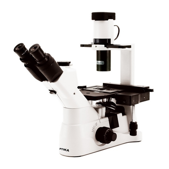
2.0 COMPONENTS Objectives LED housing Phase contrast slider - 10X (PH) - 20X (PH) - 40X Illumination bracket Eyepieces Condenser Trinocular viewing Stage insert tube (fixed Objective turret (Nosepiece) (fixed) Microscope base Stage (fixed) - Stage extension - Glass stage Page 6... -
Page 7: Installation
3.0 INSTALLATION 3.1 INSTALLATION DIAGRAM The following figure shows the installation sequence of the components. The number in the figure shows the installation steps. ► Before installing, be sure every component is clean. Take care not to scratch parts or surfaces. ► Store the supplied hexagon wrench in a safe place. When changing the components, you will need it again. Microscope base Condenser illumination unit Mechanical stage LED housing Eyepiece Stage extension Objectives Glass stage... - Page 8 3.0 INSTALLATION 3.2 INSTALLATION STEPS 3-2-1 Installing the condenser illumination unit and the LED housing (fig. 3) 1. Insert the condenser illumination unit (1) into the bracket, according to figure . 2. Turn the condenser illumination unit clockwise about 90°, with the “AS” mark of filter holder (3) facing forwards. Align the screw of the condenser illumination unit and the hole of the holder, then screw the bolt in the hole with the supplied Figure 3...
- Page 9 3.0 INSTALLATION 3-2-3 Installing the stage extension and the mechanical stage (fig. 6) (Not included in LT version) The stage extension can be installed on either side of the stage to en- large the working surface. The mechanical stage must be installed on the side opposite the extension. For right-handed operators, the mechanical stage is normally installed on the right side.
- Page 10 3.0 INSTALLATION 3-2-7 Connecting the power cord (fig.10, 11 & 12) ► Do not tension or otherwise stress the power cord. If bent, the wires may easily break. 1. Turn the main switch (1) to “O”(off) before connecting the power cord. 2. Insert the plug into the power jack (2) of the microscope. 3. Plug the power cord (4) into the mains socket. Check for a safe Figure 10 connection.
-
Page 11: Adjusting The Microscope
4.0 ADJUSTING THE MICROSCOPE Aperture diaphragm adjustment lever Color filter holder Phase centering bolt Phase contrast slider Dioptric adjustment ring Light path selector lever Fine focus knob Tension Coarse adjustment collar focus knob Page 11... - Page 12 4.0 ADJUSTING THE MICROSCOPE 4-1 MICROSCOPE BASE 4-1-1 Turning on the LED (fig. 13) Connect the power, turn on the main switch (1). 4-1-2 Adjusting the brightness (fig. 13) Turn the brightness adjustment knob (2) to increase and de- crease the brightness. Figure 13 4-1-3 Adjusting the tension (fig. 14) ► The coarse focusing knob (1) is preadjusted to a tight tension upon leaving the factory. If the nosepiece drops down by itself, or the specimen de- focuses while adjusting the fine focus knob (3), the coarse focus knob is too loose.
- Page 13 4.0 ADJUSTING THE MICROSCOPE 4-2-2 Moving the specimen Move the specimen to the desired position by freehand or by tur ning the knobs of the mechanical stage. ► When switching objectives, take care not to touch the adaptor plates with the objectives, as their weight may damage the front lens. 4-3 VIEWING TUBE 4-3-1 Dioptric adjustment (fig. 17) 1. Look into the right eyepiece with your right eye only, and focus on the specimen.
- Page 14 4.0 ADJUSTING THE MICROSCOPE 4-4 ILLUMINATION UNIT 4-4-1 Using color filters (fig. 20) Selecting the appropriate color filters according your need. You can stack a group of color filters in the filter holder, if you ensure that they are level and that the whole thickness is less Figure 20 than 11mm.
-
Page 15: Phase Contrast Operation
5.0 PHASE CONTRAST OPERATION 5-1 IDENTIFYING THE COMPONENTS 5-1-1 Phase contrast objectives (fig. 22) The magnifications of the optional phase contrast objectives are: 10X and 20X. These objectives are marked “PH”. Figure 22 Mount the objectives on the turret using the same procedures as the standard objectives (3-2-2). -
Page 16: Microphotography And Video
6.0 MICROPHOTOGRAPHY AND VIDEO 6-1 VIDEO PORT (VIDEO) 6-1-1 Selecting the light path (fig. 26) 1. To activate the video port, pull out the light path selector lever. ► For observation of dark specimens, first focus, then pull out the lever. 6-1-2 Installing the video adapter (fig. 27) 1. Loosen the locking bolt (1) on the trinocular viewing tube, and take out the dust cap (2). Figure 26 2. -
Page 17: Technical Specifications
6.0 MICROPHOTOGRAPHY AND VIDEO 6-2-3 Focus During a binocular observation at 20% brightness, look at the image on the video imaging system, refocusing the adapter if necessary. 7.0 TECHNICAL SPECIFICATIONS 7-1 MAIN SPECIFICATIONS Illumination Light source type X-LED8 with white 8W LED; light intensity control using a knob on left side of the frame. -
Page 18: Troubleshooting
8.0 TROUBLESHOOTING Under certain conditions, some no-fault factors will bring a reversible influence to the instrument’s performance. If this happens, please take proper measures according to the follow table. If you can’t solve the trouble as indicated, please contact the sales department of our Company. PROBLEM REASON SOLUTION... - Page 19 8.0 TROUBLESHOOTING 6. One side of the image The nosepiece is not in the cen- Turn the nosepiece to a click stop is out of focus. ter of the light path The specimen is out of place Place the specimen flat on the stage. (tilted) The optical performance of the Use a cover glass of better quality...
-
Page 20: Recovery And Recycling
9.0 RECOVERY AND RECYCLING Art.13 Dlsg 25 july 2005 N°151. “According to directives 2002/95/EC, 2002/96/EC and 2003/108/EC relating to the reduction in the use of hazardous substances in electrical and electronic equipment and waste dispo- sal.” The basket symbol on equipment or on its box indicates that the product at the end of its useful life should be collected separately from other waste. - Page 22 INDICE 1.0 AVVERTENZE pagina 24 2.0 COMPONENTI pagina 26 3.0 INSTALLAZIONE pagina 27 4.0 REGOLAZIONE DEL MICROSCOPIO pagina 31 5.0 OSSERVAZIONI IN CONTRASTO DI FASE pagina 35 6.0 MICROFOTOGRAFIA E VIDEO pagina 36 7.0 SPECIFICHE TECNICHE pagina 37 8.0 RISOLUZIONE DEI PROBLEMI pagina 38 9.0 MISURE ECOLOGICHE pagina 40...
- Page 23 Optika ricorda che il presente manuale contiene informazioni importanti per un uso sicuro e una corretta ma- nutenzione dello strumento. Esso deve quindi essere accessibile a chiunque lo utilizzi.
- Page 24 1.0 AVVERTENZE SICUREZZA Non lasciare lo strumento alla luce solare diretta, in am- bienti con temperature o umidità elevate, né in luoghi sporchi e polverosi. Assicurarsi che il piano portaprepa- rati sia livellato, orizzontale e stabile. Durante gli spostamenti del microscopio, tenere lo stru- mento con una mano sulla parte bassa del tubo por- taoculari (1) e l’altra sul braccio porta illuminatore (2) (Figura 1).
- Page 25 1.0 AVVERTENZE SIMBOLI DI SICUREZZA Simbolo Significato La superficie potrebbe scottare. Non toccare. Leggere attentamente le istruzioni prima dell’uso. Un utilizzo scorretto potrebbe portare a lesioni o malfunzionamento. Interruttore principale acceso – ON. Interruttore principale spento – OFF. Pagina 25...
- Page 26 2.0 COMPONENTI Obiettivi Allogiamento LED Slider per contrasto di fase - 10X (PH) - 20X (PH) - 40X Braccio porta-illuminatore Oculari Condensatore Tubo di inquadratura Inserto piano trinoculare (fisso) Torretta portaobiettivi (Revolver) Base del microscopio (fissa) Piano (fisso) - Prolungamento del piano - Piano in vetro Pagina 26...
- Page 27 3.0 INSTALLAZIONE 3.1 SCHEMA D’INSTALLAZIONE Nella figura seguente si mostra la sequenza di installazione dei componenti. A ciascun numero in figura corrisponde un passaggio nella procedura di installazione. ► Assicurarsi che tutti i componenti siano puliti prima di procedere all’installazione. Assicurarsi che non vi siano graffi sulle componenti ottiche né sulle superfici. ► Riporre la chiave esagonale fornita in dotazione in un posto sicuro, perché sarà neces- saria di nuovo al momento della sostituzione delle parti. Base del microscopio Gruppo condensatore-illuminatore Tavolo traslatore Allogiamento LED Oculari Prolungamento del...
- Page 28 3.0 INSTALLAZIONE 3.2 PROCEDURA D’INSTALLAZIONE 3-2-1 Installazione del gruppo condensatore-illuminatore e dell’alloggiamento LED (fig. 3) 1. Inserire il gruppo condensatore-illuminatore (1) nell’appo- sito braccio (si veda figura 3). 2. Ruotare il gruppo in senso orario di circa 90°: il marchio “AS” del portafiltri (3) deve essere rivolto in avanti. Allinea- re la vite del gruppo condensatore-illuminatore con il foro nel portafiltri, quindi avvitare il bullone nel foro servendosi Figura 3...
- Page 29 3.0 INSTALLAZIONE 3-2-3 Installazione del prolungamento del piano e del tavolo traslatore (fig. 6) (Non incluso nella versione LT) Il prolungamento può essere montato su entrambi i lati del piano por- tapreparati per aumentare la superficie di lavoro. Il tavolo traslatore va installato sul lato opposto a quello del prolungamento. Per operatori destrimani, solitamente il tavolo traslatore si installa sul lato destro.
- Page 30 3.0 INSTALLAZIONE 3-2-7 Collegamento del cavo di alimentazione (fig.10, 11 & 12) ► Non allungare o sottoporre a nessuna tensione il cavo di alimentazione. Se lo si piega, il filo può rompersi facilmen- 1. Mettere l’interruttore (1) su “O”(off) prima di collegare il cavo di alimentazione. 2. Inserire la spina nella presa jack (2) del microscopio. Figura 10 3. Inserire il cavo di alimentazione (4) nella presa di rete. Attenzio- ne alla sicurezza del collegamento.
- Page 31 4.0 REGOLAZIONE DEL MICROSCOPIO Leva di regolazione del diaframma di apertura Portafiltri per filtri cromatici Bullone di centratura fase Slider per contrasto di fase Anello di regolazione diottrica Selezionatore percorso luminoso Manopola di Anello di regolazione della Manopola di regolazione della messa a fuoco regolazione della tensione...
- Page 32 4.0 REGOLAZIONE DEL MICROSCOPIO 4-1 BASE DEL MICROSCOPIO 4-1-1 Accensione dell’illuminazione (fig. 13) Collegare l’alimentazione, quindi accendere l’interruttore (1). 4-1-2 Regolazione della luminosità (fig. 13) Ruotare l’apposita manopola per aumentare o diminuire la luminosità. Figura 13 4-1-3 Regolazione della tensione (fig. 14) ► La manopola di regolazione macrometrica (1) è pre-re- golata sulla tensione massima prima della spedizione. Se la torretta portaoculari cade da sola oppure il preparato perde la messa a fuoco durante la regolazione micrometrica (3), significa che la manopola di regolazione macrometrica è...
- Page 33 4.0 REGOLAZIONE DEL MICROSCOPIO 4-2-2 Spostamento del preparato Si può sistemare il preparato nella posizione desiderata a mano op- pure operando sui comandi coassiali del tavolo traslatore. ► Nel cambiare gli obiettivi, fare attenzione a non toccare i piani adattatori con gli obiettivi, in quanto il loro peso potrebbe dan- neggiare la lente frontale. 4-3 OCULARI 4-3-1 Compensazione diottrica (fig. 17) 1. Osservare e mettere a fuoco il preparato guardando con l’occhio destro attraverso l’oculare destro.
- Page 34 4.0 REGOLAZIONE DEL MICROSCOPIO 4-4 GRUPPO ILLUMINATORE 4-4-1 Utilizzo filtri cromatici (fig. 20) Scegliere i filtri cromatici a seconda delle proprie esigenze. Nel portafiltri si possono ammucchiare una serie di filtri purché siano disposti piani e lo spessore totale sia inferiore a 11mm. Figura 20 Filtro cromatico IF550 Filtro cromatico a contrasto singolo...
- Page 35 5.0 OSSERVAZIONI IN CONTRASTO DI FASE 5-1 IDENTIFICAZIONE DEI COMPONENTI 5-1-1 Obiettivi per contrasto di fase (fig. 22) Il potere di ingrandimento degli obiettivi opzionali per contrasto di fase sono i seguenti: 10X, 20X. Tali obiettivi sono contrassegnati “PH”. Montare gli obiettivi sulla torretta con la stessa procedura utilizzata Figura 22 per gli obiettivi standard (2-2-3).
- Page 36 6.0 MICROFOTOGRAFIA E VIDEO 6-1 TUBO PER ACQUISIZIONI VIDEO 6-1-1 Selezione del percorso luminoso (fig. 26) 1. Per attivare l’acquisizione video, tirare verso l’esterno la levet- ta di selezione del percorso luminoso.. ► Per l’osservazione di preparati scuri, mettere a fuoco il preparato prima di estrarre la levetta. 6-1-2 Installazione dell’adattatore video (fig. 27) 1. Svitare il bullone di bloccaggio (1) sul tubo trinoculare e ri- Figura 26 muovere il tappo antipolvere (2).
- Page 37 6.0 MICROFOTOGRAFIA E VIDEO 6-2-3 Messa a fuoco Nelle osservazioni binoculari con luminosità al 20%, guardare all’immagine sul sistema immagini video, rifocalizzando l’a- dattatore se necessario. 7.0 SPECIFICHE TECNICHE 7-1 SPECIFICHE TECNICHE Illuminazione Sorgente luminosa di tipo X-LED8 con LED bianco 8W. Controllo della luminosità...
- Page 38 8.0 RISOLUZIONE DEI PROBLEMI In certe condizioni alcuni fattori possono causare una riduzione delle prestazioni dello strumento. In tal caso, nella tabella seguente si indicano alcune misure per ripristinare il buon funzionamento del microscopio. Se tuttavia il problema non si risolve, si consiglia di contattare l’assistenza tecnica. PROBLEMA CAUSA SOLUZIONE...
- Page 39 8.0 RISOLUZIONE DEI PROBLEMI 6. Un lato dell’immagine Il revolver non è al centro del Ruotare il revolver finché non si blocca con non è a fuoco percorso luminoso un click Il preparato non si trova nella Posizionare il preparato orizzontalmente sul posizione corretta (es.
- Page 40 9.0 MISURE ECOLOGICHE Ai sensi dell’articolo 13 del decreto legislativo 25 luglio 2005 n°151. “Attuazione delle direttive 2002/95/CE, 2002/96/CE e 2003/108/CE, relative alla riduzione dell’uso di sostanze pericolose nelle apparecchiature elet- triche ed elettroniche, nonché allo smaltimento dei rifiuti”. Il simbolo del cassonetto riportato sulla apparecchiatura o sulla sua confezione indica che il prodotto alla fine della propria vita utile deve essere raccolto separatamente degli altri rifiuti.
- Page 42 Puig i Pidemunt, nº 28 1º 2ª - (Pol. Ind. Plà d’en Boet) 08302 MATARO (Barcelona) España Tel: +34 937.586.245 +34 937.414.529 New York Microscope Company Inc 100 Lauman Lane, Suite A, Hicksville, New York 11801, USA Tel.: 877.877.7274 - Fax: 516.801.2046 www.microscopeinternational.com - info@nyscopes.com OPTIKA MICROSCOPES - ITALY www.optikamicroscopes.com - info@optikamicroscopes.com...
Need help?
Do you have a question about the XDS-3 and is the answer not in the manual?
Questions and answers