Table of Contents
Advertisement
Quick Links
Smart encoders & actuators
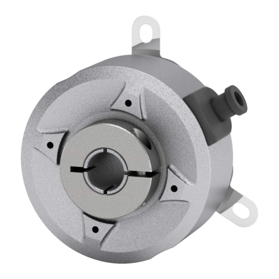
C50MI
C50MA
• Small size hollow shaft encoder with magnetic scanning
• Several mounting options with fixing plates
• Incremental: TTL/RS-422 output, resolution up to 65,536 PPR
• Absolute: SSI & BiSS C-mode interfaces, resolution up to 35
bits, singleturn and multiturn versions
• Feedback on motors and automation applications
Suitable for the following models:
C50MI-L1-...
•
C50MA-BG1-...
•
C50MA-SC1-...
•
Lika Electronic
User's guide
•
Tel. +39 0445 806600
Incremental and absolute rotary encoder
General contents
Preliminary information
1 - Safety summary
2 - Identification
3 - Mounting instructions
4 - Electrical connections
5 - Incremental signals
6 - SSI interface
7 - BiSS C-mode interface
•
info@lika.biz
10
11
17
21
23
27
•
www.lika.biz
7
8
Advertisement
Table of Contents

Related Manuals for Lika C50MI-L1 Series


Summary of Contents for Lika C50MI-L1 Series
-
Page 1: User's Guide
1 - Safety summary C50MA-BG1-... • 2 - Identification C50MA-SC1-... • 3 - Mounting instructions 4 - Electrical connections 5 - Incremental signals 6 - SSI interface 7 - BiSS C-mode interface Lika Electronic • Tel. +39 0445 806600 • info@lika.biz • www.lika.biz... - Page 2 Tous droits réservés. This document and information contained herein are the property of Lika Electronic s.r.l. and shall not be reproduced in whole or in part without prior written approval of Lika Electronic s.r.l. Translation, reproduction and total or partial modification (photostat copies, film and microfilm included and any other means) are forbidden without written authorisation of Lika Electronic s.r.l.
-
Page 3: Table Of Contents
Table of Contents User's guide......................................1 Table of Contents....................................3 Subject Index......................................5 Typographic and iconographic conventions........................6 Preliminary information..................................7 1 - Safety summary............................8 1.1 Safety......................................8 1.2 Electrical safety..................................8 1.3 Mechanical safety..................................9 2 - Identification............................10 3 - Mounting instructions......................... 11 3.1 Encumbrance sizes................................11 3.2 Installation with standard fixing plate (KIT MOL2428)..................13 3.3 Installation with B type fixing plate (KIT MOL2546)....................14 3.4 Installation with D type fixing plate (KIT MOL2433)....................15... - Page 4 7.3 Application notes................................29 7.4 Recommended BiSS input circuit..........................30 8 – Warnings and errors..........................31 8.1 Warnings....................................31 Signal warning.................................31 Frequency warning..............................31 8.2 Errors......................................31 Startup error................................31 Command execution in progress........................31 Consistency error..............................32 Communication error............................32 Invalid checksum..............................32...
-
Page 5: Subject Index
Subject Index Command execution in progress......31 Invalid checksum..............32 Communication error.............32 Consistency error.............32 Position.................28 CRC..................29 Signal warning..............31 Error..................28 Startup error..............31 Frequency warning............31 Warning................29... -
Page 6: Typographic And Iconographic Conventions
In this guide, to make it easier to understand and read the text the following typographic and iconographic conventions are used: parameters and objects both of Lika device and interface are coloured in GREEN; • alarms are coloured in RED;... -
Page 7: Preliminary Information
Preliminary information This guide is designed to provide the most complete and exhaustive information the operator needs to correctly and safely install and operate the C50MI incremental rotary encoder and the C50MA absolute rotary encoder. C50Mx encoder can be equipped with incremental interface (C50MI model: Line Driver RS-422 signal level) and with absolute interface (C50MA model: SSI and BiSS C-mode interfaces). -
Page 8: Safety Summary
• failure to comply with these precautions or with specific warnings elsewhere in this manual violates safety standards of design, manufacture, and intended use of the equipment; • Lika Electronic assumes no liability for the customer's failure to comply with these requirements. 1.2 Electrical safety •... -
Page 9: Mechanical Safety
C50MI • C50MA • Incremental, SSI & BiSS out by the user. We suggest providing the ground connection as close as possible to the encoder. 1.3 Mechanical safety • Install the device following strictly the information in the “3 - Mounting instructions”... -
Page 10: Identification
Information is listed in the delivery document too. Please always quote the order code and the serial number when reaching Lika Electronic. For any information on the technical characteristics of the product refer to the technical catalogue. -
Page 11: Mounting Instructions
C50MI • C50MA • Incremental, SSI & BiSS 3 - Mounting instructions WARNING Installation must be carried out by qualified personnel only, with power supply disconnected and mechanical parts compulsorily in stop. 3.1 Encumbrance sizes (values are expressed in mm) Figure 1 - C50MI / C50MA with standard fixing plate (KIT MOL2428) Figure 2 - C50MI / C50MA with version B fixing plate (KIT MOL2546) MAN C50MI_C50MA E 1.0.odt... - Page 12 C50MI • C50MA • Incremental, SSI & BiSS Figure 3 - C50MI / C50MA with version D fixing plate (KIT MOL2433) MAN C50MI_C50MA E 1.0.odt 3 - Mounting instructions 12 of 36...
-
Page 13: Installation With Standard Fixing Plate (Kit Mol2428)
C50MI • C50MA • Incremental, SSI & BiSS 3.2 Installation with standard fixing plate (KIT MOL2428) Mount the encoder on the motor shaft; do not force the encoder shaft; • fasten the fixing plate 1 to the rear of the motor using 3 M3 x 8 •... -
Page 14: Installation With B Type Fixing Plate (Kit Mol2546)
C50MI • C50MA • Incremental, SSI & BiSS 3.3 Installation with B type fixing plate (KIT MOL2546) Mount the encoder on the motor shaft; do not force the encoder shaft; • fasten the fixing plate 1 to the rear of the motor using 2 M4 x 8 •... -
Page 15: Installation With D Type Fixing Plate (Kit Mol2433)
C50MI • C50MA • Incremental, SSI & BiSS 3.4 Installation with D type fixing plate (KIT MOL2433) Mount the encoder on the motor shaft; do not force the encoder shaft; • make sure the anti-rotation pin 6, that is secured to the rear of the •... - Page 16 C50MI • C50MA • Incremental, SSI & BiSS NOTE You are strongly advised not to carry out any mechanical operations (drilling, milling, etc.) on the encoder shaft. This could cause serious damages to the internal parts and an immediate warranty loss. Please contact our technical personnel for the complete availability of "custom made"...
-
Page 17: Electrical Connections
C50MI • C50MA • Incremental, SSI & BiSS 4 - Electrical connections WARNING Power supply must be turned off before performing any electrical connection! If wires of unused signals come in contact, irreparable damage could be caused to the device. Thus they must be cut at different lengths and insulated singularly. -
Page 18: M8 Cable Specifications
C50MI • C50MA • Incremental, SSI & BiSS 4.3 M8 cable specifications Model LIKA HI-FLEX sensor cable type M8 Cross section 2 x 0.25 mm + 6 x 0.14 mm (24/26 AWG) Jacket Polyurethane (PUR, ether base) tinned copper braid, coverage 85%... -
Page 19: Biss C-Mode Interface
C50MI • C50MA • Incremental, SSI & BiSS 4.9 BiSS C-mode interface For complete information on the BiSS C-mode interface please refer to the “7 - BiSS C-mode interface” section on page 27. 4.10 Absolute resolution C50MA encoder with absolute interface can have a singleturn resolution of 32,768 cpr (15 bits), 131,072 cpr (17 bits), 262,144 cpr (18 bits), and 524,288 cpr (19 bits). -
Page 20: Zero Setting Input
C50MI • C50MA • Incremental, SSI & BiSS 4.12 Zero setting input (C50MA-BG1-... and C50MA-SC1-... only) The output position information at a decided point in the shaft rotation can be set to 0. The Zero setting input allows the operator to activate the zero value through an input signal sent by a PLC or other controller. -
Page 21: Incremental Signals
C50MI • C50MA • Incremental, SSI & BiSS 5 - Incremental signals 5.1 AB signals C50MI-L1... encoder provides incremental signals AB0 /ABO. The resolution of the incremental signals AB /AB can be within a range of 1 to 65,536 PPR. The output circuit is the Line Driver / Line Driver (RS-422)/TTL level type. -
Page 22: Reference (0) Signal
C50MI • C50MA • Incremental, SSI & BiSS 5.2 Reference (0) signal The Reference signal (0, /0) provides a single datum position in the revolution of the shaft for use at power-up or following a loss of power. The signal is synchronized with A and B channels and has a duration of one measuring step (90 electrical degrees), see Figure 5. -
Page 23: Ssi Interface
C50MI • C50MA • Incremental, SSI & BiSS 6 - SSI interface Order code: C50MA-BG1-… SSI, MSB Left Aligned protocol, binary code 6.1 SSI (Synchronous Serial Interface) – General Information Synchronous Serial SSI (the acronym for Interface) is a synchronous point-to-point serial interface engineered unidirectional... -
Page 24: Msb Left Aligned Protocol
C50MI • C50MA • Incremental, SSI & BiSS At each change of the clock signal and at each subsequent rising edge (2) one bit is clocked out at a time, up to LSB, so completing the data word transmission. The cycle ends at the last rising edge of the clock signal (3). This means that up to n + 1 rising edges of the clock signals are required for each data word transmission (where n is the bit resolution);... -
Page 25: Recommended Transmission Rates
C50MI • C50MA • Incremental, SSI & BiSS The transmitted position value has the following structure: Bit structure C50MA-BG1-17-... C50MA-BG1-18-... C50MA-BG1-19-... C50MA-BG1-15M-... C50MA-BG1-17M-... C50MA-BG1-18M-... C50MA-BG1-19M-... value … 6.3 Recommended transmission rates The SSI interface has a frequency of data transmission ranging between 100 kHz and 2 MHz. -
Page 26: Recommended Ssi Input Circuit
C50MI • C50MA • Incremental, SSI & BiSS 6.5 Recommended SSI input circuit MAN C50MI_C50MA E 1.0.odt 6 - SSI interface 26 of 36... -
Page 27: Biss C-Mode Interface
7 - BiSS C-mode interface Order code: C50MA-SC1-... BiSS C-mode Lika encoders are always Slave devices and comply with the “BiSS C-mode interface” and the “Standard encoder profile”. Refer to the official BiSS website for all information not listed in this manual (www.biss-interface.com). -
Page 28: Single Cycle Data Scd
C50MI • C50MA • Incremental, SSI & BiSS 7.2 Single Cycle Data SCD 7.2.1 SCD structure SCD data has a variable length according to the resolution of the encoder. It is nbitres+7 long where “nbitres” is the resolution of the encoder expressed in bits. It consists of the following elements: position value (Position), 1 error bit nE (Error), 1 warning bit nW (Warning) and a 6-bit CRC Cyclic Redundancy Check (CRC). -
Page 29: Warning
C50MI • C50MA • Incremental, SSI & BiSS Warning (1 bit) It is intended to communicate the normal or fault status of the Slave. When nW = “0” (low active), a warning is active in the system. For a comprehensive list of the available warning messages and their meaning please refer to the “8 –... -
Page 30: Recommended Biss Input Circuit
C50MI • C50MA • Incremental, SSI & BiSS 7.4 Recommended BiSS input circuit MAN C50MI_C50MA E 1.0.odt 7 - BiSS C-mode interface 30 of 36... -
Page 31: Warnings And Errors
• occurred. Switch the power off and then on again. If the error is still active, please contact Lika's After-Sales Service. The signals are not proper or their amplitude is • too high or too low. It may be due to one of the following reasons: the encoder is not mounted properly (see the “3 - Mounting instructions”... -
Page 32: Consistency Error
I2C. Switch the power off and then on again. If the error is still active, please contact Lika's After-Sales Service. Invalid checksum An invalid checksum occurred in the internal RAM. - Page 33 This page intentionally left blank...
- Page 34 This page intentionally left blank...
- Page 35 This page intentionally left blank...
- Page 36 Ce dispositif doit être alimenté par un circuit de Classe 2 ou à très basse tension ou bien en appliquant une tension maxi de 30Vcc. Voir le code de commande pour la tension d'alimentation. Lika Electronic Via S. Lorenzo, 25 •...
Need help?
Do you have a question about the C50MI-L1 Series and is the answer not in the manual?
Questions and answers