Advertisement
Quick Links
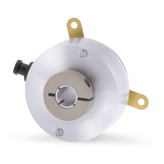
ROTAPULS
Incremental encoders
Series
Warning: encoders having ordering code ending with "/Sxxx" may have mechanical and electrical characteristics different from standard and be supplied with additional documentation for special connections (Technical Info).
Attenzione: gli encoder con codice di ordinazione finale "/Sxxx" possono avere caratteristiche meccaniche ed elettriche diverse dallo standard ed essere provvisti di documentazione aggiuntiva per cablaggi speciali (Technical info).
Achtung: Geräte, deren Bestellschlüssel mit der Kennung /Sxxx enden, können in ihren mech. und elektr. Eigenschaften vom Standard abweichen. Diese werden daher mit einer ergänzenden Dokumentation ausgeliefert (Technical info).
Atención: los encoders con código de pedido acabado en "/Sxxx" pueden tener caracteristicas mecánicas y eléctricas diferentes a las basicas y documentación adicional relativa a conexiones especiales (Technical Info).
Attention: les encodeurs avec code de ordre terminant en "/Sxxx" peuvent avoir des caractéristiques mécaniques et électriques différentes du standard et documentation additionnelle pour les câblages spéciaux (Technical info).
EN
Mounting instructions
• Fasten the fixing plate 1 to the rear of the motor using provided screws 2;
• mount the encoder on the motor shaft;
• keep the encoder at a safety distance from the motor to prevent the fixing
plate 1 from warping;
• fix the collar 3 to the encoder shaft (we suggest applying threadlocker to
screw 3);
• the fixing plate 1 must allow the encoder to move radially in order to absorb
the misalignment between motor shaft and encoder shaft. Fixing plate 1 is
supplied already fixed to the encoder.
ES
Instrucciones de montaje
• Fijar la placa de fijación 1 en la parte posterior del motor mediante los
tornillos previstos 2;
• montar el encoder en el eje del motor;
• asegurarse de que el encoder y el motor sean a una distancia de seguridad
para evitar la deformación de la placa de fijación 1;
• fijar el collar 3 en el eje del encoder (aconsejamos aplicar fijador de roscas);
• la placa de fijación 1 debe permitir el movimiento radial del encoder
suficiente para absorbir el desalineamento entre eje motor y eje encoder. La
placa de fijación 1 viene provista ya montada.
Signals
A
/A
Brown
Marrone
A, B, 0 outputs
Braun
-
(5 wires cable)
Marrón
Marron
EDE 9 pin
1
2
Yellow
Blue
A, /A, B, /B, 0, / 0
Giallo
Blu
outputs
Gelb
Blau
(8 wires cable)
Amarillo
Azul
Jaune
Bleu
Installation has to be carried out with power supply disconnected.
L'installazione deve essere eseguita in assenza di tensione.
Der Anschluss darf nur bei ausgeschalteter Versorgungsspannung erfolgen.
La instalación sólo debe ser efectuada en ausencia total de tensión.
Le montage du dispositif doit être effectué en
C50 • C51
IT
• Fissare la molla di fissaggio 1 sul retro del motore per mezzo delle viti 2;
• inserire l'encoder sull'albero motore;
• tenere l'encoder a una corretta distanza dal motore per evitare la
deformazione della molla di fissaggio 1;
• fissare il collare 3 dell'albero encoder (si consiglia un ulteriore fissaggio della
vite 3 con frenafilletti);
• la molla di fissaggio 1 deve consentire all'encoder un gioco radiale
sufficiente per assorbire il disallineamento tra albero motore e albero
encoder. La molla di fissaggio 1 viene fornita già assemblata sull'encoder.
FR
• Fixer la plaquette de fixation 1 à la partie postérieure du moteur en utilisant
les vis pourvues 2;
• monter l'encodeur sur l'arbre du moteur;
• assurer une distance de sureté entre l'encodeur et le moteur afin de ne
déformer pas la plaquette de fixation 1;
• fixer le collier 3 au niveau de l'arbre encodeur (on conseille d'appliquer du
frein-filet sur la vis 3);
• la plaquette de fixation 1 doit permettre le mouvement radial de l'encodeur
afin d'absorber le mauvais alignement entre l'arbre moteur et l'arbre
encodeur. La plaquette de fixation 1 est fournie déjà installée.
Electrical connections
B
/B
0
/0
Blue
White
Blu
Bianco
Blau
-
Weiß
-
Azul
Blanco
Bleu
Blanc
3
4
5
6
Green
Orange
White
Grey
Verde
Arancione
Bianco
Grigio
Grün
Orange
Weiß
Grau
Verde
Anaranjado
Blanco
Gris
Vert
Orange
Blanc
Gris
absence totale de tension.
Istruzioni di montaggio
Instructions de montage
+VDC
0VDC
Shield
Red
Black
Shield
Rosso
Nero
Schermo
Rot
Schwarz
Schirm
Rojo
Negro
Malla
Rouge
Noir
Blindage
8
9
Case
Red
Black
Shield
Rosso
Nero
Schermo
Rot
Schwarz
Schirm
Rojo
Negro
Malla
Rouge
Noir
Blindage
DE
Montagehinweise
• Befestigungsfeder 1 auf der Rückseite des Motors anschrauben;
• Geber auf die Motorwelle montieren;
• Geber auf die richtige Distanz zum Motor setzen so dass die
Befestigungsfeder 1 nicht deformiert wird;
• Klemmflansch 3 festschrauben (Schraube 3 könnt ggf. zusätzlich mit
geeignetem Klebstoff befestigt werden);
• die Befestigungsfeder 1 nimmt die radiale Toleranzen zwischen Motor- und
Geberwelle auf, sie ist bei Auslieferung bereits am Geber montiert.
Connector type
male frontal side
maschio lato contatti
Aufsicht Stiftseite
macho lado contactos
mâle côté contacts
Wires not used must be cut at different
lengths and insulated singularly
EDE 9 pin
Advertisement

Subscribe to Our Youtube Channel
Related Manuals for Lika ROTAPULS C50 Series


Summary of Contents for Lika ROTAPULS C50 Series
- Page 1 ROTAPULS Incremental encoders C50 • C51 Series Warning: encoders having ordering code ending with "/Sxxx" may have mechanical and electrical characteristics different from standard and be supplied with additional documentation for special connections (Technical Info). Attenzione: gli encoder con codice di ordinazione finale “/Sxxx” possono avere caratteristiche meccaniche ed elettriche diverse dallo standard ed essere provvisti di documentazione aggiuntiva per cablaggi speciali (Technical info). Achtung: Geräte, deren Bestellschlüssel mit der Kennung /Sxxx enden, können in ihren mech.
- Page 2 • utiliser le dispositif tout en respectant les caractéristiques environnementales mentionnées par le constructeur. Lika Electronic reserves the right to make changes in specifications without prior notice – Lika Electronic si riserva il diritto di apportare modifiche senza preavviso - Die Fa. Lika Electronic behält sich das Recht zu Änderungen ohne Vorankündigung vor - Informaciones pueden ser modificadas por Lika Electronic sin preaviso –...
Need help?
Do you have a question about the ROTAPULS C50 Series and is the answer not in the manual?
Questions and answers