Advertisement
Quick Links
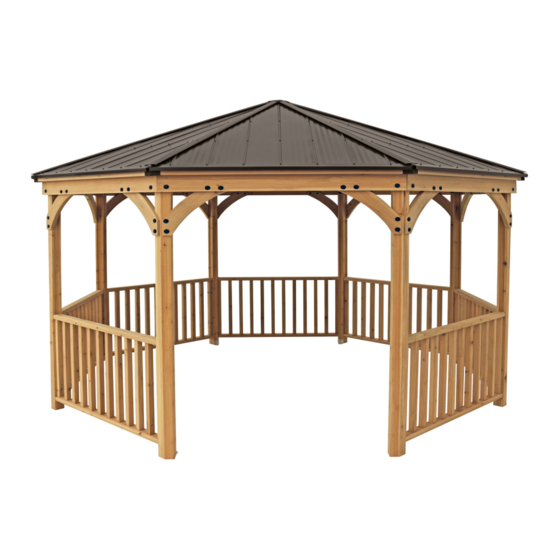
MERIDIAN OCTAGON GAZEBO
Installation and Operating Instructions – YM11924
YM11924 - Meridian Octagon
IMPORTANT, RETAIN FOR FUTURE REFERENCE: READ CAREFULLY
12' 0"
Revised 04-26-2021
3.658 m
12'
(3.658 m)
Yardistry – North America
12'
12' 0"
Toll Free Customer Support:
(3.658 m)
3.658 m
1.888.509.4382
info@yardistrystructures.com
www.yardistrystructures.com
Height: 9' 11-5/16" (3.03 m)
Y40000-924
Advertisement

Related Manuals for Yardistry MERIDIAN OCTAGON YM11924


Summary of Contents for Yardistry MERIDIAN OCTAGON YM11924
- Page 1 Installation and Operating Instructions – YM11924 YM11924 - Meridian Octagon IMPORTANT, RETAIN FOR FUTURE REFERENCE: READ CAREFULLY 12' 0" Revised 04-26-2021 3.658 m 12’ (3.658 m) Yardistry – North America 12’ 12' 0" Toll Free Customer Support: (3.658 m) 3.658 m 1.888.509.4382 info@yardistrystructures.com www.yardistrystructures.com...
-
Page 2: Important Safety Notice
Wood is NOT flame retardant and will burn. Grills, fire pits and chimineas are a fire hazard if placed too close to a Yardistry structure. Consult user’s manual of the grill, fire pit or chimnea for safe distances from combustible materials. - Page 3 Limited Warranty Yardistry warrants that this product is free from defect in materials and workmanship for a period of one (1) year from the original date of purchase. In addition, for any product with lumber, all lumber is warranted for five (5) years against rot and decay. This warranty applies to the original owner and registrant and is non-transferable.
-
Page 4: Instructions For Proper Maintenance
Instructions for Proper Maintenance Your Yardistry structure is designed and constructed of quality materials. As with all outdoor products it will weather and wear. To maximize the enjoyment, safety and life of your structure it is important that you, the owner, properly maintain it. -
Page 5: Assembly Tips
Assembly Tips Following are some helpful tips to make the assembly process smooth and efficient. PRE-ASSEMBLIES: (i.e. Post and Beam Assemblies, Roof Rafter Assembly, etc) • Work on a raised, solid and flat surface such as, a table or saw horse. •... - Page 6 Permanent Installation Examples Note: It is critically important you start with square, solid and level footings, concrete pad or deck to attach your Pavilion. 135" 3.43 We supply Post Mounts with this structure which gives you the flexibility to permanently install your structure Post to Post to a pre-existing or new wood or concrete surface.
- Page 7 Permanent Installation Examples cont. Concrete Patio [min. 12’ 3” x 12’ 3” (3.734 m x 3.734 m)] with 6” (15.24 cm) clearance on all sides CONCRETE APPLICATION CONCRETE APPLICATION CONCRETE APPLICATION CONCRETE APPLICATION Anchoring Hardware not included STEP 12- Anchoring A: After the all the walls h Wood Deck [min.
-
Page 8: Part Identification
Part Identification ( Dimensions are approximate and are shown to assist in the identification of parts for assembly. Actual dimensions may be smaller or larger. 1pc. (1059) - Post Left 2184.4mm (86") Y70131-1059 1pc. (1061) - Post Right 2184.4mm (86") Y70131-1061 6pc. - Page 9 Part Identification ( Dimensions are approximate and are shown to assist in the identification of parts for assembly. Actual dimensions may be smaller or larger. 8pc. (1067) - LT Corner Rafter 2032mm (80") Y50131-1067 8pc. (1068) - RT Corner Rafter 2032mm (80") Y50131-1068 8pc.
-
Page 10: Hardware Identification
Hardware Identification ( Dimensions are approximate and are shown to assist in the identification of parts for assembly. Actual dimensions may be smaller or larger. 8pc. - RT Panel 8pc. - LT Panel (Y01033-356) 1pc. -Octagon (Y01033-357) Gazebo Roofing Set (Y70833-356) 8pc. - Page 11 Hardware Identification ( Dimensions are approximate and are shown to assist in the identification of parts for assembly. Actual dimensions may be smaller or larger. 8pc. 1/4 x 2" Hex Bolt - (Y07718-220) 24pc. 1/4 x 2-3/4 Hex Bolt - (Y07718-223) #12 x 1-1/2"...
- Page 12 Step 1: Inventory Parts - Read This Before Starting Assembly STOP STOP STOP STOP This is the time for you to inventory all your hardware, wood and accessories, referencing the parts identification sheets. This will assist you with your assembly. •...
- Page 13 A: Place 12 spindles (1066) in the filler (1065) slots to get spacing. Attach Bot Rail (1063) usin 3” Wood Screws. Step 2: Rail Assemblies Part 1 B: Remove filler (1065) and attach to the other end of the Spindles, using #8 x 2” Wood Screw - RAILS A: Place 12 (1066) Spindles into the slots of (1065) Filler.
- Page 14 Step 2: Rail Assemblies Part 2 C: On top of (1065) Filler and flush to each end, place (1064) Top Rail. Attach (1065) Filler to (1064) Top Rail with three #8 x 1-1/2” Wood Screws as shown in F2.3 and F2.4. D: Repeat Steps A - C six more times to create seven Rail Assemblies.
- Page 15 Step 3: Post Assemblies A: Flush to the bottom of one (1059) Post Left and one (1061) Post Right place one Post Mount tight to the inside of each post then attach with two #10 x 1-1/4” Pan Screws per Post Mount. (F3.1, F3.2, F3.3 and F3.4) B: Flush to the bottom of each (1056) Post Main place one Post Mount tight to the inside of each post then attach with two #10 x 1-1/4”...
- Page 16 Step 4: Attach Rail Assemblies to Posts Part 1 STEP 4 - POST/RAIL Assembly Assembly A: Place one (1056) Post Main on each side of one Rail Assembly. Rail Assembly should sit tight to top of post DA: Continue attaching each Rail Assem side of one Rail Assembly and attach using (2) insert.
-
Page 17: Post Assembly
Step 4: Attach Rail Assemblies to Posts Part 2 D: Place one (1056) Post Main on one side of one Rail Assembly and (1059) Post Left on the other side. Rail Assembly should sit tight to top of post insert. See F4.7 and F4.8 for correct positioning of posts. At an angle, attach (1064) Top Rail to posts with two #8 x 2-1/2”... - Page 18 Step 4: Attach Rail Assemblies to Posts Part 3 F: Repeat Steps D and E using one (1056) Post Main with one (1061) Post Right. See F4.11 and F4.12 for correct positioning of Posts. (F4.13, F4.14, F4.15, F4.16, F4.17 and F4.18) STEP 4 - POST/RAIL Assembly LAYOUT FOR 1 RIGHT POST ASSEMBLY F4.13...
- Page 19 STEP 5 - Wall Assembly -(x2) STEP 5 - Wall Assembly -(x2) Follow steps below, then complete another assembly Step 5: Main Wall Assembly A: Place Beam (1062) onto one Rail/Post frame from previous step. ˜ush t o each end then Follow steps below, then complete another assembly attach togeth-er using #8 x 3”...
- Page 20 B: Attach Short Gusset Left (1073) and Right (1072) using 5/16” x 2¼” Hex BLT (1/4 LG Washe Bracket) Nut, Lock Washer), then tighten corner using 1/4 x 1-15/16” Lag Screws (1/4” Lg Washers) B: Attach Short Gusset Left (1073) and Right (1072) using 5/16” x 2¼” Hex BLT (1/4 LG Washer, 5/16 T- Nut, Lock Washer), then tighten corner using 1/4 x 1-15/16”...
-
Page 21: Step 7: Frame Assembly
Step 7: Frame Assembly STEP 8 - Frame Assembly -Connect Left and Right Walls Part 1 A: Place Beam (1062) in between Right and Left Walls from previous step, ˜ush t o each end then attach together using #8 x 3” Wood Screws and 1/4 x 5“ Hex Bolt (1/4” Large Washer, Lock Nut) A: Move Wall Assemblies to the final location. - Page 22 Step 7: Frame Assembly Part 2 D: Place one Rail Assembly between Left Wall Assembly and one Main Wall Assembly. Rail Assembly should sit tight to top of post inserts. At an angle, attach (1064) Top Rail to posts with two #8 x 2-1/2” Wood Screws. (F7.4, F7.5 and F7.6) E: For each (1066) Spindle which is next to a post, at an angle, pre-drill with a 1/8”...
- Page 23 Step 7: Frame Assembly Assembly Cont'd Part 3 2) in between Left Wall from previous step and 1 Wall Assembly, flush to h together using #8 x 3” Wood Screws and 1/4 x 5“ Hex Bolt (1/4” Large et Left (1073) and Right (1072) using 5/16” x 2¼” Hex BLT (1/4 LG Washer, 5/16 F: Place one (1062) Beam in between walls so it is flush to the top of previously installed (1062) Beams.
- Page 24 Step 7: Frame Assembly Part 4 I: Place remaining Rail Assembly between Right Wall Assembly and Main Wall Assembly. Rail Assembly should sit tight to top of post inserts. At an angle, attach (1064) Top Rail to posts with two #8 x 2-1/2” Wood Screws. (F7.12, F7.13 and F7.14) J: For each (1066) Spindle which is next to a post, at an angle, pre-drill with a 1/8”...
- Page 25 STEP 11 - Frame Assembly Cont'd Step 7: Frame Assembly A: Place Beam (1062) in between common Wall from previous step and Right Wall Assembly ,flush Part 5 t o each end then attach together using #8 x 3” Wood Screws and 1/4 x 5“ Hex Bolt (1/4” Large Washer, Lock Nut) B: Attach Short Gusset Left (1073) and Right (1072) using 5/16”...
- Page 26 Step 7: Frame Assembly Part 6 M: In the places shown in F7.19, measure 2-1/4” (5.72 cm) down from the top of the Post then attach Post Roof Tie Bracket to Posts with two #10 x 1-1/4” Pan Screws per bracket. (F7.19 and F7.20) F7.19 F7.20 Post Roof...
- Page 27 Step 8: Anchoring Frame Assembly A: Make sure the distance between the entrance posts are the same at the top and bottom of the assembly. (F8.1) B: Make sure each corner is square and level. The diagonal distance between the hole in the Post Mount of two opposite Post Assemblies should be 137-3/8”...
- Page 28 Step 9: Roof Panel Frame Part 1 A: On each side of one (1071) Rafter Centre place one (1067) LT Corner Rafter and one (1068) RT Corner Rafter so the tops are flush. Attach through (1067) LT Corner Rafter and (1068) RT Corner Rafter with two #8 x 1-1/2”...
- Page 29 Step 9: Roof Panel Frame STEP 14- Roof Rafter Assembly Part 2 A: At the bottom, attach (1072) Fascia, using #8 x 2-1/2” B: Place one (1072) Fascia on the bottom of (1071) Rafter Centre, (1067) LT Corner Rafter and (1068) RT Wood Screws.
- Page 30 Step 9: Roof Panel Frame STEP 15- Roof Rafter Assembly Part 3 A: Attach (1069) Top Strap and (1070) Bottom Strap, using #8 x 1-1/2” Wood C: Place one (1069) Top Strap and one (1070) Bot Strap in the grooves of the rafters so the outside edges are Screws.
- Page 31 STEP 16- Rafter Brackets Step 10: Attach Rafter Beam Brackets A: Attach 7 Rafter Beam Brackets to the Centre Rafter (1071) using Hex Bolt 1/4 x 2” (1/4” Lock nut, 2x 1/4” x 5/16” Flat washers) B: Leave one panel without the Rafter to Beam bracket installed. A: On the back of seven Roof Panel Frames place one Rafter Beam Bracket on each (1071) Rafter Centre then loosely attach each bracket to rafters with one 1/4 x 2”...
-
Page 32: Handle With Care
STOP STOP STOP STOP INSTALLING ROOFING MATERIAL CAUTION! Roofing material may have sharp edges! Wear gloves! HANDLE WITH CARE! Place roofing material on a non-abrasive surface before assembly as it can bend, dent and scratch easily. WARNING – DO NOT OVER TIGHTEN ROOFING SCREWS! Over tightening screws will cause roofing material to crush. - Page 33 STOP STOP STOP STOP INSTALLING ROOFING MATERIAL CAUTION! Roofing material may have sharp edges! Wear gloves! BE SURE TO REMOVE ALL PLASTIC COVERING, ON BOTH SIDES OF THE ALUMINUM PANELS AND TRIM, DIRECTLY BEFORE INSTALLING EACH PIECE. (One side is clear and the other is blue, both must be removed.) Example #1 Example #2 Overtightened and Crushed...
- Page 34 STEP 17- Roof Panels B: Make sure Roof Panels are Flush t o the TOP of the Roof Frame Assembly. Step 11: Attach Roof Panels A: Attach LT and RT Roof Panels using (21) #8 Rooÿng screws per Roof/Frame Assembly. B: Make sure Roof Panels are Flush t o the TOP of the Roof Frame Assembly.
- Page 35 Step 12: Attach Roof Edge A: Place one Roof Edge on the bottom of Roof Panel Frame. Attach Roof Edge with seven #8 x 1” Roofing Screws. (F12.1 and F12.2) B: Repeat Step A for each Roof Panel Frame. #8 x 1” Hex Roofing Screws F12.1 STEP 19- Roof Edges...
- Page 36 Step 13: Attach Ridge Clips A: Place Weather Seal on the inside of two Ridge Clips then place one Ridge Clip flush to each side of Roof Panel Frame and 2-1/4” (5.72 cm) up from the bottom of (1067) LT Corner Rafter and (1068) RT Corner Rafter, make sure not to compress Weather Seal.
- Page 37 Step 14: Attach Roof Panels to Frame Part 1 A: Starting to the right of the opening in the frame assembly, with four assemblers lift two Roof Panel Frames with Rafter Beam Brackets up and over frame assembly taking care not to drag roof panels on beams. One assembler must remain on a ladder to hold Roof Panel Frames in place until secured.
- Page 38 Step 14: Attach Roof Panels to Frame Part 2 D: Attach two remaining Roof Panel Frames with Rafter Beam Brackets up and over frame assembly, taking care STEP 22 -2 panel Install not to drag roof panels on beams, and attach with three 1/4 x 2-3/4” Hex Bolts (with two 1/4-5/16” large washers and one 1/4”...
- Page 39 A: Take Roof Peak Assembly (Octagon Roof Peak Set, Peak Cap, Peak Post) and loosely attach at the apex of the Octagon. Step 15: Roof Cap Assembly A: Insert one Carriage Bolt with Contoured Washer through the top of Peak Cap, into Peak Post. Attach Spring Clip to Peak Post.
- Page 40 Step 16: Attach Roof Cap and Final Roof Panel STEP 24 -Final Roof Panel A: With the Peak Cap Assembly at top of Octag A: Place Roof Cap Assembly in gap at the top of the Roof Panels. Peak Cap to be lined up with Corner Rafters. Connect the last panel (without Roof to Beam Bra (F16.1 and F16.2) previous step, then tighten all bolts using using 1/4...
- Page 41 Step 17: Tighten Rafter Bolts A: Follow the sequence in F17.1 to tighten the bottom bolts. While tightening bolts have a helper push up the centre of the roof. The helper on the outside of the frame makes sure corners are aligned. (F17.1) B: Tighten remaining bolts, keeping Corner Rafter flush at the bottom.
- Page 42 he last Roof to Beam Bracket , using 1/4 x 2-3/4“ Hex Bolts (1/4” Large Nut), Step 18: Attach Rafter Beam Bracket reviously installed Roof to Beam Brackets using (3) #12 x 1-1/2" Pan cket. While fastening, make sure that fascia is tight to the beam A: On the final Roof Panel Frame attach one Rafter Beam Bracket on (1071) Rafter Centre with one 1/4 x 2”...
- Page 43 Step 19: Secure Roof Panels A: Where each Roof Panel Frame meet attach panels together through (1072) Fascia with one #8 x 2-1/2” Wood Screw per corner. A helper may need to lift the centre of Roof Panels to bring the corners tight together. (F19.1 and F19.2) F19.1 7 -Tie Fascia's together...
- Page 44 Step 20: Attach Ridge Caps A: Slide each Ridge Cap over the Ridge Clips, with cut edge leading, towards the centre of the roof until they are under the Peak Cap, lifting Peak Cap by pushing up the Peak Loop so Ridge Cap fit under Peak Cap. Attach each Ridge Cap using two #8 x 3/4”...
- Page 45 Step 21: Attach Corner Caps A: At each corner place one Corner Cap tight to (1072) Fascia, push up so the bottom is tight to the bottom of the assemblies then attach with four #8 x 3/4” Sheet Metal Screws per Corner Cap. (F21.1 and F21.2) F21.1 STEP 29 -Corner Caps Attach all (8) Corner Caps , using #8 x 7/8"...
- Page 46 Step 22: Secure Peak Base Plate A: Attach Peak Base Plate to each (1071) Rafter Centre with eight #10 x 1-1/4” Pan Screws. To ensure Peak Base Plate is flat install screws in a criss-cross sequence. Screws may go in on an angle. (F22.1) (1071) Rafter (1071) Rafter Peak Base Plate...
- Page 47 Step 23: Attach Plaque A: Attach Yardistry Plaque to a prominent location on your Gazebo with two #10 x 1-1/4” Pan Screws. This provides warnings concerning safety and important contact information. A tracking number is provided to allow you to get critical information or order replacement parts for this specific model. (F23.1 and F23.2) F23.1...
- Page 48 NOTES support@yardistrystructures.com...
- Page 49 NOTES support@yardistrystructures.com...
- Page 50 Atención a: Servicio de Atención al Cliente À l’attention de: Service à la clientèle Yardistry would like to say “Thank you” for your time and feedback. Yardistry quiere “Agradecerle” por su tiempo y su opinión. Yardistry aimerait vous remercier d’avoir pris le temps de répondre au sondage.
Need help?
Do you have a question about the MERIDIAN OCTAGON YM11924 and is the answer not in the manual?
Questions and answers