Advertisement
Quick Links
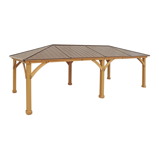
12' x 24' MERIDIAN WOOD GAZEBO
with ALUMINUM ROOF
Installation and Operating Instructions – YM11937
IMPORTANT, RETAIN FOR FUTURE REFERENCE: READ CAREFULLY
Revised 07-21-2022
7.451 m
24' 5-3/8"
3.708 m
Yardistry – North America
12' 2"
Toll Free Customer Support:
1.888.509.4382
info@yardistrystructures.com
www.yardistrystructures.com
HEIGHT:
3.099 m / 10'2"
Y40000-937
Advertisement

Subscribe to Our Youtube Channel
Related Manuals for Yardistry MERIDIAN YM11937


Summary of Contents for Yardistry MERIDIAN YM11937
- Page 1 ALUMINUM ROOF Installation and Operating Instructions – YM11937 IMPORTANT, RETAIN FOR FUTURE REFERENCE: READ CAREFULLY Revised 07-21-2022 7.451 m 24’ 5-3/8” 3.708 m Yardistry – North America 12’ 2” Toll Free Customer Support: 1.888.509.4382 info@yardistrystructures.com www.yardistrystructures.com HEIGHT: 3.099 m / 10’2”...
- Page 2 Wood is NOT flame retardant and will burn. Grills, fire pits and chimineas are a fire hazard if placed too close to a Yardistry structure. Consult user’s manual of the grill, fire pit or chimnea for safe distances from combustible materials.
- Page 3 Limited Warranty Yardistry warrants that this product is free from defect in materials and workmanship for a period of one (1) year from the original date of purchase. In addition, for any product with lumber, all lumber is warranted for five (5) years against rot and decay. This warranty applies to the original owner and registrant and is non-transferable.
- Page 4 Instructions for Proper Maintenance Your Yardistry structure is designed and constructed of quality materials. As with all outdoor products it will weather and wear. To maximize the enjoyment, safety and life of your structure it is important that you, the owner, properly maintain it.
- Page 5 Assembly Tips Following are some helpful tips to make the assembly process smooth and efficient. PRE-ASSEMBLIES: (i.e. Post and Beam Assemblies, Roof Rafter Assembly, etc) • Work on a raised, solid and flat surface such as, a table or saw horse. •...
- Page 6 Permanent Installation Examples Note: It is critically important you start with square, solid and level footings, concrete pad or deck to attach your Pergola Room. We supply Post Mounts with this structure which gives you the flexibility to permanently install your structure to a pre-existing or new wood or concrete surface.
- Page 7 Permanent Installation Examples cont. Concrete Patio [min. 3.616 m x 7.364 m (11’ 10-3/8” x 24’ 1-15/16”)] with 15.24 cm (6”) clearance on all sides Anchoring Hardware not included Wood Deck [min. 3.616 m x 7.364 m (11’ 10-3/8” x 24’ 1-15/16”)] with 15.24 cm (6”) clearance on all sides Anchoring Hardware not included Post...
- Page 8 Part Identification ( Dimensions are approximate and are shown to assist in the identification of parts for assembly. Actual dimensions may be smaller or larger. 24pc. (422) Plinth 190.5mm (7-1/2") Y50131-422 Y70131-705 Y70131-706 6pc. (705) Gusset RT 1015mm (39-15/16") 6pc. (706) Gusset LT 1015mm (39-15/16") 2pc.
- Page 9 Part Identification ( Dimensions are approximate and are shown to assist in the identification of parts for assembly. Actual dimensions may be smaller or larger. 4pc. (624) Rafter Corner Left 2597.8mm (102¼") Y50131-624 4pc. (623) Rafter Corner Right 2597.8mm (102¼") Y50131-623 2pc.
- Page 10 Part Identification ( Dimensions are approximate and are shown to assist in the identification of parts for assembly. Actual dimensions may be smaller or larger. 2pc. (681) Left Top Strap 495.1mm (19-1/2") Y50131-681 2pc. (682) Right Top Strap 495.1mm (19-1/2") Y50131-682 2pc.
- Page 11 Hardware Identification ( Dimensions are approximate and are shown to assist in the identification of parts for assembly. Actual dimensions may be smaller or larger. 12pc. 1/4 x 2-3/4 Hex Bolt - (Y07718-223) 30pc. 1/4 x 2 Hex Bolt - (Y07718-220) 22pc.
- Page 12 Hardware Identi cation Dimensions are approximate and are shown to assist in the identi cation of parts for assembly. Actual dimensions may be smaller or larger. 4pc. - Short Panel Left 4pc. - Long Panel Right (Y01033-200) (Y01033-197) 12pc. - Middle Panel (Y01033-196) 1pc.
- Page 13 Hardware Identification ( Dimensions are approximate and are shown to assist in the identification of parts for assembly. Actual dimensions may be smaller or larger. Roof Peak Set 1pc. - 4pc. (12 x 24) (Y70829-465) Roof Peak Bracket (Y00429-125) 6pc. 1/4"...
- Page 14 Step 1: Inventory Parts - Read This Before Starting Assembly STOP STOP STOP STOP This is the time for you to inventory all your hardware, wood and accessories, referencing the parts identification sheets. This will assist you with your assembly. •...
- Page 15 Step 2: Post Assemblies A: At the bottom of one (696) 6 x 6 Post insert one 5/16” T-Nut on the outside of two sides, as shown in F2.3. B: At the bottom of the same (696) 6 x 6 Post place two Post Mounts tight to the bottom and inside faces on the sides as shown in F2.1 and F2.2.
- Page 16 Step 3: Short Beam Assembly Part 1 A: Connect one (1002) Beam Short Left and one (1003) Beam Short Right using two 5/16 x 1-1/2” Hex Bolts (with 5/16” lock washer, 1/4-5/16” large washer and 5/16” t-nut) as shown in F3.1 and F3.2. B: Connect one (1004) Beam Short End to each end of one (1005) Beam Short Centre using two 5/16 x 1-1/2”...
- Page 17 Step 3: Short Beam Assembly Part 2 D: Place one Short Beam L-R Assembly tight to one Short Beam End Assembly so the ends are flush. Match the bolt holes in each (1004) Beam Short End with the bolt holes in (1002) Beam Short Left and (1003) Beam Short Right.
- Page 18 Step 4: Long Beam Assembly Part 1 A: Connect one (1199) Outer End to each end of one (1196) Beam using four 5/16 x 1-1/2” Hex Bolts (with 5/16” lock washer, 1/4-5/16” large washer and 5/16” t-nut) as shown in F4.1 and F4.2. Notice orientation of angled ends.
- Page 19 Step 4: Long Beam Assembly Part 2 D: Connect one (1201) Inside Middle Beam to each end of one (1198) Inside Beam using four 5/16 x 1-1/2” Hex Bolts (with 5/16” lock washer, 1/4-5/16” large washer and 5/16” t-nut). At the end of each (1201) Inside Middle Beam connect one (1197) Beam End with two 5/16 x 1-1/2”...
- Page 20 Step 4: Long Beam Assembly Part 3 F: Place one Inside Beam Assembly tight to one Outer Beam Assembly so the ends are flush and the angled ends match. Bolt heads from the Outer Beam Assembly must be on the outside and Short Beam Inserts will be on the inside.
- Page 21 Step 5: Frame Assembly and Anchoring Part 1 A: On a hard, flat surface place one Short Beam Assembly against the outside of two Post Assemblies, flush to the tops and outside corners. Attach Beam to Post, through the bottom hole, with one 3/8 x 9-1/4” Hex Bolt (with two 3/8”...
- Page 22 Step 5: Frame Assembly and Anchoring Part 2 Note: The bevelled ends on each gusset should always face away from the wood it is attaching to. C: Make sure each Short Side assembly is square with the Post Assembly then facing one Short Beam Assembly from the outside place one (705) Gusset RT on the right hand side so the top fits tight to the Beam Assembly and the bottom fits tight to the Post Assembly.
- Page 23 Step 5: Frame Assembly and Anchoring Part 3 F: Move your Post Assemblies to the final location. Make sure the ground is flat and level before continuing YM11937 - 12 x 24 Meridian Gazebo assembly. G: With helpers stand up Short Side Assemblies then place one Long Beam Assembly against the outside of two Post Assemblies, flush to the tops and outside corners and tight to Short Beam Assembly.
- Page 24 Step 5: Frame Assembly and Anchoring Part 4 H: From inside the assembly, centre one Post Assembly over middle bolt holes in each Long Beam Assembly then place Steel Cable with Bracket against both Post Assemblies so the angle of the bracket faces up and is over the top bolt hole.
- Page 25 Step 5: Frame Assembly and Anchoring Part 5 Note: The bevelled ends on each gusset should always face away from the wood it is attaching to. I: Make sure the Frame Assembly is square and level then facing one Long Beam Assembly from the outside place one (705) Gusset RT on the right hand side Post Assembly and one on the left side of the middle Post Assembly so the tops fit tight to the Beam Assembly and the bottom fits tight to the posts.
- Page 26 Step 5: Frame Assembly and Anchoring Part 6 L: Attach Long and Short Beam Assemblies to outside Post Assemblies with two 5/16 x 4-3/4” Lag Screws (with 1/4-5/16” large washer) per corner in the remaining holes. (F5.13) M: Attach Long Beam Assembly to both middle Post Assemblies through the bottom holes with one 5/16 x 4-3/4” Lag Screw (with 1/4-5/16”...
- Page 27 Step 6: Attach Brackets A: On each middle Post Assembly place one Large Centre Roof Bracket, centred to each Long Beam Assembly so they are flush and tight to the inside face of each beam then attach to Post Assembly with two #12 x 1-1/2” Pan Screws per bracket.
- Page 28 Step 7: Fascia Beam Assembly - Small Roof Rafter A: Tightly connect one (627) Fascia Left Short and one (628) Fascia Right Short using one 5/16 x 1-1/2” Hex Bolt (with 5/16” lock washer, 1/4-5/16” large washer and 5/16” t-nut) as shown in F7.1 and F7.2. Repeat to make a second Fascia Beam Assembly.
- Page 29 Step 8: Small Roof Assembly Part 1 A: On each side of one (634) Rafter place one (624) Rafter Corner Left and one (623) Rafter Corner Right so the tops and edges are flush then attach with two #8 x 2-1/4” Wood Screws per side. (F8.1 and F8.2) B: Place Fascia Beam Assembly from Step 7 on the bottom of (624) Rafter Corner Left, (623) Rafter Corner Right and (634) Rafter so the sides are flush then attach with one #8 x 2-1/2”...
- Page 30 Step 8: Small Roof Assembly Part 2 D: Place one (629) Rafter Short RT, one (632) Rafter Centre RT, one (631) Rafter Centre LT and one (630) Rafter Short LT over the pilot holes in the Fascia Beam Assembly so they are flush to the top of the assembly and tight to both (623) Rafter Corner Right and (624) Rafter Corner Left, as shown in F8.6.
- Page 31 Step 8: Small Roof Assembly Part 3 E: Place one (636) Top Strap, one (637) Mid Strap, one (687) Bottom Strap LT and one (688) Bottom Strap RT in the notches of each rafter so the ends do not overhang the outside edges of the outside boards. (687) Bottom Strap LT and (688) Bottom Strap RT sit tight together.
- Page 32 Step 8: Small Roof Assembly Part 4 F: Attach (629) Rafter Short RT and (632) Rafter Centre RT to (623) Rafter Corner Right and (631) Rafter Centre LT and (630) Rafter Short LT to (624) Rafter Corner Left with two #8 x 1-1/2” Wood Screw per rafter. (F8.11 and F8.12) G: Attach (636) Top Strap, (637) Mid Strap and (687) Bottom Strap LT to rafters with 16 #8 x 1-1/2”...
- Page 33 Step 9: Attach Soffits - Small Roof Assembly A: Turn over each Small Roof Assembly then place two (648) Soffits tight together at centre of (634) Rafter and tight to the top of Fascia Beam Assembly. Attach (648) Soffits to (634) Rafter, (623) Rafter Corner Right, (624) Rafter Corner Left, (629) Rafter Short RT, (630) Rafter Short LT, (632) Rafter Centre RT and (631) Rafter Centre LT with four #8 x 1”...
- Page 34 STOP STOP STOP STOP INSTALLING ROOFING MATERIAL CAUTION! Roofing material may have sharp edges! Wear gloves! HANDLE WITH CARE! Place roofing material on a non-abrasive surface before assembly as it can bend, dent and scratch easily. WARNING – DO NOT OVER TIGHTEN ROOFING SCREWS! Over tightening screws will cause roofing material to crush.
- Page 35 STOP STOP STOP STOP INSTALLING ROOFING MATERIAL CAUTION! Roofing material may have sharp edges! Wear gloves! BE SURE TO REMOVE ALL PLASTIC COVERING, ON BOTH SIDES OF THE ALUMINUM PANELS AND TRIM, DIRECTLY BEFORE INSTALLING EACH PIECE. (One side is clear and the other is blue, both must be removed.) Example #1 Example #2 Overtightened and Crushed...
- Page 36 Step 10: Attach Roof Panels - Small Roof Assembly Part 1 A: Place one Long Panel Left on the front of one Small Roof Assembly so it is flush to the side of (624) Rafter Corner Left and a slight overhang at the bottom of the Fascia Beam Assembly. Centre holes should line up with (634) Rafter.
- Page 37 Step 10: Attach Roof Panels - Small Roof Assembly Part 2 E: Place one Short Panel Left on Small Roof Assembly so it overlaps the Long Panel Left and it is flush to the Assembly x2 sides of (624) Rafter Corner Left and a slight overhang at the bottom of the Fascia Beam Assembly. There should be no overhang at the corners.
- Page 38 Step 11: Attach Ridge Clips and Roof Edges - Small Roof A: Place one Roof Edge Left 72.2 and one Roof Edge Right 72.2 on the bottom of each Small Roof Rafter Assembly so the ends are flush with the outside ends of the Fascia Beam Assembly and meet tight in the centre. Attach both Roof Edges with 17 #8 x 1”...
- Page 39 50000- Middle Rafter Y50000-675 Step 12: Corner Roof Assemblies Part 1 Fascia A: On the left side of one (675) Middle Rafter place one (624) Rafter Corner Left so the tops and edges are flush, Middle Rafter notice on the (675) Middle Rafter the angled end at the bottom slopes down then attach with two #8 x 2-1/4” Wood Y50000-675 Screws.
- Page 40 Step 12: Corner Roof Assemblies Part 2 D: For each Right Corner Roof Assembly and each Left Corner Roof Assembly, place one (629) Rafter Short RT, one (632) Rafter Centre RT, one (631) Rafter Centre LT and one (630) Rafter Short LT over the pilot holes Middle Rafter in the (677) Right End Fascia and (676) Left End Fascia so they are flush to the top of the assembly and tight Y50000-675...
- Page 41 Y50000-686 Step 12: Corner Roof Assemblies Part 3 E: For each Left Corner Roof Panel place one (681) Left Top Strap, one (683) Left Mid Strap and one (685) Left Bot Strap in the notches of each rafter so the ends do not overhang the outside edges of the outside boards then attach with four #8 x 1-1/2”...
- Page 42 Step 12: Corner Roof Assemblies Part 4 Rafter Centre Left Rafter Centre RT Y50000- Y50000-632 G: Attach (629) Rafter Short RT and (632) Rafter Centre RT to (623) Rafter Corner Right and (631) Rafter Centre LT and (630) Rafter Short LT to (624) Rafter Corner Left with two #8 x 1-1/2” Wood Screw per rafter. (F12.13, F12.14 and F12.15) H: Attach (684) Right Mid Strap and (686) Right Bot Strap to (629) Rafter Short RT and (632) Rafter Centre RT;...
- Page 43 Step 13: Attach Soffits - Corner Roof Assemblies A: Turn over each Corner Roof Assembly then place one (690) Soffit End tight to the top of each (676) Left End Fascia and each (677) Right End Fascia. Each (690) Soffit End must be flush with the outside edge of (675) Middle Rafter.
- Page 44 Step 14: Attach Roof to Beam Brackets - Corner Roof Assemblies A: Turn the assemblies back over then on the back of each Corner Roof Assembly, through the bolt hole at the bottom of the board, loosely attach one Roof to Beam Bracket to (629) Rafter Short RT, (632) Rafter Centre RT, (630) Rafter Short LT and (631) Rafter Centre LT with one 1/4 x 2”...
- Page 45 Step 15: Attach Roof Panels - Corner Roof Assemblies IMPORTANT!: Before starting this step, be sure to refer back to pages 34 & 35 regarding correct installation and handling of the roofing. A: On the front of each Left Corner Roof Assembly place one Long Panel Left and one Short Panel Left so they are flush to the side of (624) Rafter Corner Left and the rib of Long Panel Left is centre on (675) Middle Rafter.
- Page 46 Step 16: Attach Roof Edges - Corner Roof Assemblies Assembly x2 A: On the bottom of each Left Corner Roof Assembly place one Roof Edge Left 72.2 so the holes in the Roof Edge Left line up with the holes in the panels then attach Roof Edges with nine #8 x 1” Roofing Screws per Left Corner Roof Assembly.
- Page 47 Step 17: Attach Ridge Clips - Corner Roof Assemblies A: Place one Weather Seal on the inside of four Ridge Clip 102.5 then place one Ridge Clip 102.5 on each (623) Rafter Corner Right and each (624) Rafter Corner Left so they cover the panels and are flush to the top, then attach with five #7 x 3/4”...
- Page 48 Step 18: Large Roof Assembly Part 1 A: On each side of one (1194) Rafter Top place one (675) Middle Rafter so the tops and edges are flush then attach with two #8 x 2-1/2” Wood Screws per side. (F18.1 and F18.2) B: Place one (1192) Mid Fascia on the bottom of each (675) Middle Rafter so the sides and top are flush then attach with one #8 x 2-1/2”...
- Page 49 Step 18: Large Roof Assembly Part 2 D: Place three (633) Centre Rafters over the pilot holes in (1192) Mid Fascia and (1194) Rafter Top so they are flush to the top of each board, as shown in F18.5. Make sure (633) Centre Rafters are square to (1192) Mid Fascia and (1194) Rafter Top then attach (1194) Rafter Top to rafters with two #8 x 2-1/4”...
- Page 50 Step 18: Large Roof Assembly Part 3 E: Place three (1193) Centre Straps in the notches of each (675) Middle Rafter and each (633) Centre Rafter so the ends are flush to the outside edges of (675) Middle Rafters. Make sure assembly is square then attach with 10 #8 x 1-1/2”...
- Page 51 Step 18: Large Roof Assembly Part 4 F: Turn over each Large Roof Assembly then place one (1195) Soffit tight to the top of (1192) Mid Fascia. (1195) Soffit must be flush with the outside edge of (675) Middle Rafter. Attach (1195) Soffit to each (675) Middle Rafter and each (633) Centre Rafter with five #8 x 1”...
- Page 52 Step 19: Attach Roof to Beam Brackets - Large Roof Assemblies A: On the back of each Large Roof Assembly, through the bolt hole at the bottom of the board, loosely attach one Roof to Beam Bracket to the two outside (633) Centre Rafters with one 1/4 x 2” Hex Bolt (with two 1/4-5/16” large washers and one1/4”...
- Page 53 Step 20: Attach Roof Panels - Large Roof Assemblies Part 1 IMPORTANT!: Before starting this step, be sure to refer back to pages 34 & 35 regarding correct installation and handling of the roofing. A: Turn over Large Roof Assemblies, make sure they are still square. Place three Middle Panels flush to the top and sides of (1194) Rafter Top and (675) Middle Rafter.
- Page 54 Step 20: Attach Roof Panels - Large Roof Assemblies Part 2 B: Attach panels to (675) Middle Rafter, (1194) Rafter Top and each (1193) Centre Strap in the remaining holes with 32 #8 x 1” Roofing Screws as shown in F20.5. Do not install screws along the bottom row. C: Repeat Steps A and B for each Large Roof Assembly.
- Page 55 Step 21: Attach Roof Edges - Large Roof Assemblies A: On the bottom of each Large Roof Assembly place one Ridge Edge Middle so the holes line up with the holes in the Middle Panels then attach with 10 #8 x 1” Roofing Screws per Large Roof Assembly. (F21.1 and F21.2) F21.1 Middle Panel Ridge...
- Page 56 Step 22: Attach Ridge Clips - Large Roof Assemblies A: Place one Weather Seal 75-1/2 on the inside of eight Ridge Clip 73.5 then place one Ridge Clip 73.5 on each (675) Middle Rafter on each Large Roof Assembly so they cover the panels and are flush to the tops. The bottom edge of each Ridge Clip 73.5 should be 2-1/4”...
- Page 57 Step 23: Attach Large Roof Assemblies to Frame Part 1 F23.1 A: With all four assemblers lift one Large Roof Large Roof Assembly Assembly with Spacers up so it sits on the Spacers Long Beam Assembly and one (675) Middle Long Beam Rafter sits in Large Centre Roof Bracket on Assembly...
- Page 58 Step 23: Attach Large Roof Assemblies to Frame Part 2 D: Repeat Steps A - C for the remaining two Large Roof Assemblies. (F23.5 and F23.6) E: Attach Large Centre Roof Brackets and (675) Middle Roof Rafters together with one 1/4 x 3-1/2” Hex Bolt (with two 1/4-5/16”...
- Page 59 Step 23: Attach Large Roof Assemblies to Frame Part 3 F: Attach (675) Middle Rafters from each connecting Large Roof Assembly with three 1/4 x 3” Hex Bolts (with two 1/4-5/16” large washers and one 1/4” lock nut) per connection. (F23.8 and F23.9) F23.8 Large Roof Assembly Parts removed...
- Page 60 Step 23: Attach Large Roof Assemblies to Frame Part 4 G: Attach one Roof to Beam Bracket to the remaining (633) Centre Rafters on each Large Roof Assembly with one 1/4 x 2” Hex Bolt (with two 1/4-5/16” large washers and one 1/4” lock nut) per bracket. (F23.10 and F23.11) H: From the outside of the assembly have one person push one Large Roof Assembly in so (1195) Soffit sits against the Long Beam Assembly and two people pushing up at the peak.
- Page 61 Step 24: Place Peak Cap Assembly on Roof Panels Part 1 A: Place two Centre Peak Caps so they are tight together then place one Peak Cap Link under Centre Peak Caps and attach with six 1/4 x 1/2” Pan Bolts (with 1/4” lock nut). (F24.1 and F24.2) B: Slide one Peak Cap Detail in the end of each Centre Peak Cap and attach with three 1/4 x 1/2”...
- Page 62 Step 24: Place Peak Cap Assembly on Roof Panels Part 2 C: Insert six Carriage Bolts with Contoured Washers through the top of Peak Cap Assembly. Place one Peak Post over each Carriage Bolt and secure with Spring Clips. The Spring Clip holds the assembly together. (F24.4, F24.5 and F24.6) D: With one person on each end of the roof place Peak Cap Assembly on top of Large Roof Assemblies so Carriage bolts with Peak Post fit through gaps between the roof assemblies.
- Page 63 Step 25: Attach Corner Roof Assemblies to Frame Part 1 A: Place Left Corner Roof Asssemblies on the left side of each Large Roof Assembly and the Right Corner Roof Assemblies on the right sides. You will need to lift Peak Cap Assembly to get the top under it. Make sure fascia on each panel are flush then attach (675) Middle Rafters from each connecting assembly with four 1/4 x 3”...
- Page 64 Step 25: Attach Corner Roof Assemblies to Frame Part 2 C: On each connecting (675) Middle Rafter on the Large Roof Assembly attach one Beam to Rafter Bracket per rafter using four #12 x 1-1/2” Pan Screws per bracket. (F25.4, F25.5 and F25.6) D: Tighten all Bracket bolts in the Corner Roof Assemblies.
- Page 65 Step 26: Attach Small Roof Assemblies to Frame A: With all four assemblers lift one Small Roof Assembly up and over the Short Beam Assembly. You will need to lift the Peak Cap Assembly to get the top under it. Loosely attach each (623) Rafter Corner Right to each (624) Rafter Corner Left with three 1/4 x 2-3/4”...
- Page 66 Step 27: Secure Roof Corners A: From outside the assembly attach Small Roof Assemblies and Corner Roof Assemblies together at the Fascia Beam Assembly and Left and Right End Fascias with two #8 x 2-1/2” Wood Screws per corner. A helper may need to lift the centre of the roof to bring the corners tight together.
- Page 67 Step 28: Attach Corner Caps A: At each corner place one Corner Cap tight to Fascia Assemblies and End Fascias, push up so the bottom is tight to the bottom of the fascia then attach with four #8 x 3/4” Sheet Metal Screws per Corner Cap. (F28.1 and F28.2) F28.1 F28.2...
- Page 68 Step 29: Attach Roof to Beam Brackets - Small Roof Assembly A: On each Small Roof Assembly, through the bolt hole at the bottom of the board, loosely attach one Roof to Beam Bracket to each rafter with one 1/4 x 2” Hex Bolt (with two 1/4-5/16” large washers and one1/4” lock nut) per bracket.
- Page 69 Step 30: Attach Ridge Caps to Roof Panels Part 1 A: At each corner, slide one Ridge Cap Long 81.5 over the Ridge Clips, from the bottom up with cut end leading. (F30.1 and F30.2) B: Slide Ridge Cap Short 25.2 over the Ridge Clips leading with the insert end to push the Ridge Cap Long 81.5 to the top, lifting Peak Cap Assembly so Ridge Cap Long 81.5s fit under.
- Page 70 Step 30: Attach Ridge Caps to Roof Panels Part 2 C: Remove the #8 x 1” Roofing Screws from each Roof Edge Left, Roof Edge Middle and Roof Edge Right where each Corner Roof Assemby and each Large Roof Assembly connect. Two screws per location. (F30.6 and F30.7) D: Place one Roof Edge Centre over each connecting seam, tight to Roof Edges and attach with previously...
- Page 71 Step 30: Attach Ridge Caps to Roof Panels Part 3 E: At each Corner Roof Assembly and Large Roof Assembly connection, slide one Ridge Cap Middle over the Ridge Clips, from the bottom up to the top, with cut end leading. Slide under Peak Cap Assembly. Attach with two #8 x 3/4”...
- Page 72 Step 31: Secure Roof Peak Detail Part 1 A: Insert one 1/4” Nut into each Peak Loop. Be careful nut is loose and will fall out until attached to Carriage Bolt. Only 2 are used in Part 1, the remaining 4 will be used in Part 2. (F31.1) B: Insert two Roof Peak Brackets through each end Carriage Bolt, so they fit over the Rafter Corners, and attach Peak Loop to Carriage Bolts then twist to tighten.
- Page 73 Step 31: Secure Roof Peak Detail Part 2 D: Place one Peak Bracket over each of the remaining Carriage Bolts then attach Peak Loop to Carriage Bolts and twist to tighten. (F31.5 and F31.6) F31.5 F31.6 Carriage Bolt Peak Bracket Peak Loop Components...
- Page 74 Step 32: Attach Tie Wrap Brackets and Ties Part 1 A: Attach one Tie Wrap Bracket tight (646) Tie Large Roof Large Roof to each end of six (646) Ties with one Assembly Assembly #10 x 1-1/4” Pan Screw per bracket F32.1 using the inside holes.
- Page 75 Step 32: Attach Tie Wrap Brackets and Ties Part 2 D: Attach one Double Tie Wrap Bracket F32.4 (646) Tie RT and one Double Tie Wrap Bracket LT Large Roof Corner Roof (646) Tie Assembly Assembly Corner Roof tight to each end of two (646) Ties with Assembly one #10 x 1-1/4”...
- Page 76 Step 33: Centre Beam Assembly Part 1 A: Place one (1202) Centre Beam Long against one (1203) Centre Beam Short. Repeat for a second set making sure the (1203) Centre Beam Short is on the opposite end of (1202) Centre Beam Long. Place all boards together, tops and ends to be flush, then attach using 18 #8 x 2-1/4”...
- Page 77 Step 33: Centre Beam Assembly Part 2 C: Remove the bolt, washers and lock nut on the F33.4 middle Post Assembly which attaches the Steel Cable with Brackets. Remove the Steel Cable with Brackets then reinstall the bolt, washers and lock nut. (F33.4, F33.5) D: Place Centre Beam Assembly against (675) Middle Rafters above middle Post Assembly.
- Page 78 Step 33: Centre Beam Assembly Part 3 F33.8 F: At the centre of the Centre Beam Assembly place (1205) Centre Upright. Attach Centre Beam Assembly to (1205) Centre Upright with 2 Large Flat Brackets using four #10 x 1-1/4” Pan Screws per bracket and (1205) Centre Upright to (1194) Rafter Tops with 2 Large Corner Brackets using four #10 x 1-1/4”...
- Page 79 Step 34: Attach Twist Brackets A: On the inside of each outside Post Assembly, place bottom of either 45° Twist Bracket LT or 45° Twist Bracket RT then attach to Post Assembly and Corner Rafter (Left or Right) with four #12 x 1-1/2” Pan Screws per bracket. (F34.1 and F34.2) Assembly x4 F34.1...
- Page 80 Step 35: Metal Hooks and Plaque A: Two 50 mm Hooks are included with this unit for attaching wiring. They can be placed anywhere along the Rafters as needed. Pre-drill with a 1/8” drill bit before installing. (F35.1 and F35.2) B: Attach Gazebo ID Plaque to a prominent location on your gazebo with two #8 x 1”...
- Page 81 NOTES support@yardistrystructures.com...
- Page 82 À l’attention de: Service à la clientèle English and French Spoken Yardistry would like to say “Thank you” for your time and feedback. Yardistry quiere “Agradecerle” por su tiempo y su opinión. Yardistry aimerait vous remercier d’avoir pris le temps de répondre au sondage.
Need help?
Do you have a question about the MERIDIAN YM11937 and is the answer not in the manual?
Questions and answers