Table of Contents
Advertisement
Quick Links
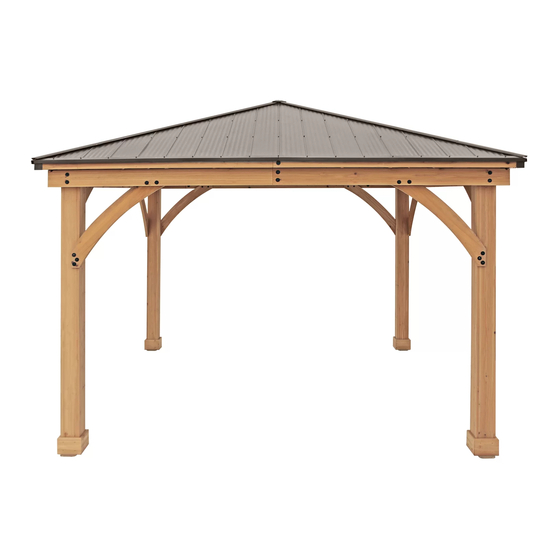
12' x 12' MERIDIAN GAZEBO
with ALUMINUM ROOF
Installation and Operating Instructions – YM11769
HEIGHT:
10'6" or 3.2m
41
Revised 06-18-2019
3.69 m
[12' 1-3/16"]
Yardistry – North America
Toll Free Customer Support: 1.888.509.4382
3.69 m
info@yardistrystructures.com
[12' 1-3/16"]
www.yardistrystructures.com
Yardistry / Selwood Products – Europe
Customer Support: +44 1284 852569
parts@selwoodproducts.com
www.selwoodproducts.com
Y40000-769
Advertisement
Table of Contents

Related Manuals for Yardistry 12’ x 12’ MERIDIAN GAZEBO YM11769


Summary of Contents for Yardistry 12’ x 12’ MERIDIAN GAZEBO YM11769
- Page 1 Installation and Operating Instructions – YM11769 HEIGHT: 10’6” or 3.2m Revised 06-18-2019 3.69 m [12’ 1-3/16”] Yardistry – North America Toll Free Customer Support: 1.888.509.4382 3.69 m info@yardistrystructures.com [12’ 1-3/16”] www.yardistrystructures.com Yardistry / Selwood Products – Europe Customer Support: +44 1284 852569 parts@selwoodproducts.com www.selwoodproducts.com Y40000-769...
- Page 2 Wood is NOT flame retardant and will burn. Grills, fire pits and chimineas are a fire hazard if placed too close to a Yardistry structure. Consult user’s manual of the grill, fire pit or chimnea for safe distances from combustible materials.
- Page 3 Limited Warranty Yardistry warrants that this product is free from defect in materials and workmanship for a period of one (1) year from the original date of purchase. In addition, for any product with lumber, all lumber is warranted for five (5) years against rot and decay. This warranty applies to the original owner and registrant and is non-transferable.
- Page 4 Instructions for Proper Maintenance Your Yardistry structure is designed and constructed of quality materials. As with all outdoor products it will weather and wear. To maximize the enjoyment, safety and life of your structure it is important that you, the owner, properly maintain it.
- Page 5 Assembly Tips Following are some helpful tips to make the assembly process smooth and efficient. PRE-ASSEMBLIES: (i.e. Post and Beam Assemblies, Roof Rafter Assembly, etc) • Work on a raised, solid and flat surface such as, a table or saw horse. •...
- Page 6 Permanent Installation Examples Note: It is critically important you start with square, solid and level footings, concrete pad or deck to attach your Pergola Room. We supply Post Mounts with this structure which gives you the flexibility to permanently install your structure to a pre-existing or new wood or concrete surface.
- Page 7 Permanent Installation Examples cont. Concrete Patio [min. 3.66 m x 3.66 m (12’ x 12’)] with 1.83 m (6”) clearance on all sides Anchoring Hardware not included Wood Deck [min. 3.66 m x 3.66 m (12’ x 12’)] with 1.83 m (6”) clearance on all sides Anchoring Hardware not included Post Mount Anchoring Hardware (not included)
- Page 8 Part Identification ( Dimensions are approximate and are shown to assist in the identification of parts for assembly. Actual dimensions may be smaller or larger. 152.4 x 152.4 x 2336.8mm (6 x 6 x 92") 4pc. (696) - M Post Y70131-696 152.4 x 152.4 x 2336.8mm (6 x 6 x 92") 1pc.
- Page 9 Hardware Identification ( Dimensions are approximate and are shown to assist in the identification of parts for assembly. Actual dimensions may be smaller or larger. 4pc. - Left Short Panel 4pc. - Right Long Panel 4pc. (Y01033-099) (Y01033-098) Ridge Cap Short 25.2 (Y01033-132) 4pc.
- Page 10 Hardware Identification ( Dimensions are approximate and are shown to assist in the identification of parts for assembly. Actual dimensions may be smaller or larger. 5/16 x 1-1/2" 24pc. Hex Bolt - (Y07718-312) 12pc. 1/4 x 2-3/4 Hex Bolt - (Y07718-223) 5/16 x 1-1/4"...
- Page 11 Step 1: Inventory Parts - Read This Before Starting Assembly STOP STOP STOP STOP This is the time for you to inventory all your hardware, wood and accessories, referencing the parts identification sheets. This will assist you with your assembly. •...
- Page 12 Step 2: Post Assemblies A: At the bottom of each (696) M Posts insert two 5/16” T-Nuts as shown in fig. 2.1 and 2.2. B: At the bottom of each (696) M Post place two Post Mounts tight to the bottom and inside faces as shown in fig. 2.1 and 2.2.
- Page 13 Step 3: Beam Assembly Part 1 A: Connect one (718) Beam End Left and one (719) Beam End Right using two 5/16 x 1-1/2” Hex Bolts (with 5/16” lock washer, 1/4 - 5/16” large washer and 5/16” t-nut) as shown in fig. 3.1 and 3.2. B: Connect one (720) Beam End Short to each end of one (717) Beam using two 5/16 x 1-1/2”...
- Page 14 Step 3: Beam Assembly Part 2 D: Place one Beam Short Assembly on one Beam End Assembly so the ends are flush. Match the bolt holes in each (720) Beam End Short with the bolt holes in (718) Beam End Left and (719) Beam End Right. Attach with 18 #8 x 2-1/2”...
- Page 15 Step 4: Frame Assembly and Anchoring Part 1 A: Move your Post Assemblies to the final location. Make sure the ground is flat and level before continuing assembly. B: With one person at each Post stand two complete Post Assemblies. A third person places one Beam Assembly against the outside of each Post, flush to the tops and outside corners.
- Page 16 Step 4: Frame Assembly and Anchoring Part 2 D: Make sure each corner is square and level then attach Beam Assemblies to Post Assemblies with two 5/16 x 4-3/4” Lag Screws (with 1/4-5/16” large washer) per corner. (fig. 4.4) E: Depending on what you are placing the Pergola Room on will determine how you anchor it to that surface. Please refer to pages 6 and 7 for installation examples.
- Page 17 Step 5: Attach Gussets and Roof Brackets Note: The bevelled ends on each gusset should always face away from the wood it is attaching to. A: Make sure the assembly is still square and level then facing one Beam Assembly place one (705) Gusset Right on the right hand side so the top fits tight to the Beam Assembly and the bottom fits tight to the Post Assembly.
- Page 18 Step 6: Fascia Beam Assembly A: Tightly connect one (341) Fascia Left and one (342) Fascia Right using one 5/16 x 1-1/4” Hex Bolt (with 5/16” lock washer, 1/4-5/16” large washer and 5/16” t-nut) as shown in fig. 6.1 and 6.2. B: Repeat Step A three more times to make four Fascia Beam Assemblies.
- Page 19 Step 7: Roof Rafter Assembly Part 1 A: On each side of one (340) Rafter place one (333) Rafter Corner Left and one (334) Rafter Corner Right so the tops and edges are flush then attach with two #8 x 2-1/4” Wood Screws per side. (Fig. 7.1 and 7.2) B: Place Fascia Beam Assembly from Step 6 on the bottom of (333) Rafter Corner Left, (334) Rafter Corner Right and (340) Rafter so the sides are flush then attach with two #8 x 2-1/4”...
- Page 20 Step 7: Roof Rafter Assembly Part 2 D: Place one (337) Strap Short in the notches of (333) Rafter Corner Left, (334) Rafter Corner Right and (340) Rafter so the ends do not overhang the outside edges of the outside boards then attach with six #8 x 1-1/2” Wood Screws.
- Page 21 Step 8: Attach Roof to Beam Brackets A: On the Back of the three Roof Rafter Assemblies, centred and flush to the bottom of (338) Rafter Short Right, (339) Rafter Short Left and (340) Rafter attach one Roof to Beam Bracket per board with one #8 x 1” Pan Screw in the bottom hole and one #12 x 1-1/2”...
- Page 22 STOP STOP STOP STOP INSTALLING ROOFING MATERIAL CAUTION! Roofing material may have sharp edges! Wear gloves! HANDLE WITH CARE! Place roofing material on a non-abrasive surface before assembly as it can bend, dent and scratch easily. WARNING – DO NOT OVER TIGHTEN ROOFING SCREWS! Over tightening screws will cause roofing material to crush.
- Page 23 STOP STOP STOP STOP INSTALLING ROOFING MATERIAL CAUTION! Roofing material may have sharp edges! Wear gloves! BE SURE TO REMOVE ALL PLASTIC COVERING, ON BOTH SIDES OF THE ALUMINUM PANELS AND TRIM, DIRECTLY BEFORE INSTALLING EACH PIECE. (One side is clear and the other is blue, both must be removed.) Example #1 Example #2 Overtightened and Crushed...
- Page 24 Step 9: Attach Roof Panels Part 1 A: Place one Left Long Panel on the front of one Roof Rafter Assembly so it is flush to the side of (333) Rafter Corner Left and a slight overhang at the bottom of the Fascia Beam Assembly. Holes should line up with (340) Rafter.
- Page 25 Step 9: Attach Roof Panels Part 2 E: Place one Left Short Panel on Roof Rafter Assembly so it overlaps the Left Long Panel and it is flush to the sides of (333) Rafter Corner Left and a slight overhang at the bottom of the Fascia Beam Assembly. There should be no overhanging at the corners.
- Page 26 Step 10: Attach Ridge Clips and Roof Edges A: Place one Roof Edge Left and one Roof Edge Right on the bottom of each Roof Rafter Assembly so the ends are flush with the outside ends of the Fascia Beam Assembly and meet tight in the centre. Attach both Roof Edges with 17 #8 x 1”...
- Page 27 Step 11: Attach Roof Panels to Frame Part 1 A: From inside of Post Assemblies measure 1524 mm (5’) to mark the centre of each Beam Assembly. (fig. 11.1) B: With all four assemblers place one Roof Panel Assembly with Roof to Beam Brackets just in front of the Post Assemblies then raise it up so the middle Roof to Beam Bracket is lined up with the centre mark.
- Page 28 Step 11: Attach Roof Panels to Frame Part 2 C: Lift a second Roof Panel Assembly with Roof to Beam Brackets over Beam Assembly taking care not to drag the panel on the beams. Make sure the middle Roof to Beam Bracket lines up to the centre mark and the Rafter Corners are flush with each other.
- Page 29 Step 11: Attach Roof Panels to Frame Part 3 E: Lift third Roof Panel Assembly with Roof to Beam Brackets over Beam Assembly taking care not to drag the panel on the beams then set in place beside the second panel. Make sure the middle Roof to Beam Bracket lines up to the centre mark.
- Page 30 Step 12: Roof Peak Assembly A: Insert Carriage Bolt through the top of Peak Cap, into Peak Post then Spring Clip. The Spring Clip holds the assembly together. (fig. 12.1) B: Insert 1/4” Nut into Peak Loop. Be careful nut is loose and will fall out until attached to Peak Cap Assembly. (fig.
- Page 31 Step 13: Attach Roof Peak to Roof Panels A: Insert Roof Peak Assembly in gap between Roof Panels. Peak Cap to be lined up with Rafter Corners. (fig. 13.1 and 13.2) B: Insert both Roof Peak Brackets through Carriage Bolt and attach Peak Loop to Carriage Bolt and twist to tighten loosely.
- Page 32 Step 14: Attach Final Roof Panel Part 1 A: Lift last Roof Panel Assembly (without Roof to Beam Brackets) over Beam Assembly taking care not to drag the panel on the beams. Panel fits under the Peak Cap, push up on Peak Loop to lift Peak Cap. The centre of the other panels may have to be pushed up to fit fourth panel.
- Page 33 Step 14: Attach Final Roof Panel Part 2 Remember to push up centre to assist with alignment. C: Starting at the bottom and working up loosely connect Roof Panel Assemblies through the Rafter Corners with three 1/4 x 2-3/4” Hex Bolts (with two 1/4-5/16” large washers and one 1/4” lock nut) per side. To align bolt holes helper on the centre ladder may have to push up in the centre of the panels and others make sure corners are aligned.
- Page 34 Step 14: Attach Final Roof Panel Part 3 D: On the fourth Roof Rafter Assembly, centred and flush to the bottom of (338) Rafter Short Right, (339) Rafter Short Left and (340) Rafter attach one Roof to Beam Bracket per board with one #8 x 1” Pan Screw in the bottom hole and one #12 x 1-1/2”...
- Page 35 Step 15: Secure Roof Corners A: Make sure middle Roof to Beam Brackets are lined up over centre mark and all are flush and tight to the Beam Assemblies. Lift in centre if needed. B: From outside the assembly attach Roof Panel Assemblies together at the Fascia Beam Assembly Ends with two #8 x 2-1/2”...
- Page 36 Step 16: Attach Corner and Beam Caps A: At each corner place one Corner Cap tight to Fascia Assemblies, push up so the bottom is tight to the bottom of the assemblies then attach with four #8 x 3/4” Sheet Metal Screws per Corner Cap. (fig. 16.1 and 16.2) Fig.
- Page 37 Step 17: Secure Roof to Beam Brackets A: From inside the assembly attach Roof to Beam Brackets to Beam Assemblies with two #12 x 1-1/2” Pan Screws per bracket. (fig. 17.1 and 17.2) Roof Panel Assembly Fig. 17.1 Inside View Beam Assembly Roof to...
- Page 38 Step 18: Secure Roof Peak Brackets A: Tighten the two screws in Roof Peak Brackets then attach to Corner Rafters in the remaining holes with fourteen #10 x 1-1/4” Pan Screws. (fig. 18.1) Fig. 18.1 Roof Peak Bracket Roof Peak Bracket Rafter Corner...
- Page 39 Step 19: Attach Ridge Caps to Roof Panels A: Slide one Ridge Cap Long 81.5 over the Ridge Clips, with cut end leading, on each corner of the assembly from the bottom up. Slide Ridge Cap Short 25.2 over the Ridge Clips leading with the insert end to push the Ridge Cap Long 81.5 to the top, lifting Peak Cap Long by pushing up the Peak Loop so Ridge Cap Long 81.5s fit under Peak Cap.
- Page 40 Step 20: Metal Hooks and Plaque Part 1 A: Two 50 mm Hooks are included with this unit for attaching wiring. They can be placed anywhere along the Rafter Corners as needed. Pre-drill with a 1/8” drill bit before installing. (fig.
- Page 41 Step 20: Metal Hooks and Plaque Part 2 B: Attach Gazebo ID Plaque to a prominent location on your gazebo with two #8 x 1” Pan Screws. This provides warnings concerning safety and important contact information. A tracking number is provided to allow you to get critical information or order replacement parts for this specific model.
- Page 42 NOTES support@yardistrystructures.com...
- Page 43 NOTES support@yardistrystructures.com...
- Page 44 Would you recommend the purchase of our products to friends and family? Comments: MAIL TO: Yardistry 375 Sligo Road W., PO Box 10 Mount Forest, Ontario, Canada Yardistry would like to say Thank You for your time and feedback. N0G 2L0 Attention: Customer Service REVISION: 09/06/2017 support@yardistrystructures.com...
Need help?
Do you have a question about the 12’ x 12’ MERIDIAN GAZEBO YM11769 and is the answer not in the manual?
Questions and answers