Advertisement
Quick Links
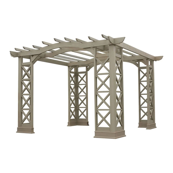
12 x 12 Arched Roof Pergola
Installation and Operating Instructions – YM11640
Yardistry – North America
Toll Free Customer Support: 1.888.509.4382
info@yardistrystructures.com
www.yardistrystructures.com
Yardistry / Selwood Products – Europe
Customer Support: +44 1284 852569
parts@selwoodproducts.com
www.selwoodproducts.com
with Plinth
Revised 11/27/2013
1
3.05 m (10')
3.66 m (12')
support@yardistrystructures.com
HEIGHT:
8'2" or 2.49m
Advertisement

Related Manuals for Yardistry YM11640


Summary of Contents for Yardistry YM11640
- Page 1 12 x 12 Arched Roof Pergola with Plinth Installation and Operating Instructions – YM11640 Revised 11/27/2013 Yardistry – North America Toll Free Customer Support: 1.888.509.4382 info@yardistrystructures.com www.yardistrystructures.com Yardistry / Selwood Products – Europe Customer Support: +44 1284 852569 parts@selwoodproducts.com 3.05 m (10’) HEIGHT: www.selwoodproducts.com...
-
Page 2: Important Safety Notice
Wood is NOT flame retardant and will burn. Grills, fire pits and chimineas are a fire hazard if placed too close to a Yardistry structure. Consult user’s manual of the grill, fire pit or chimnea for safe distances from combustible materials. -
Page 3: Limited Warranty
Limited Warranty Yardistry warrants that this product is free from defect in materials and workmanship for a period of one year from the original date of purchase. In addition, all lumber is warranted for 5 years against rot and decay. This warranty applies to the original owner and registrant and is non-transferable. -
Page 4: Instructions For Proper Maintenance
Instructions for Proper Maintenance Your Yardistry structure is designed and constructed of quality materials. As with all outdoor products it will weather and wear. To maximize the enjoyment, safety and life of your structure it is important that you, the owner, properly maintain it. - Page 5 Permanent Installation Examples Note: It is critically important you start with square, solid and level footings, concrete pad or deck to attach your Pergola Room. We supply Room L-Mounts with this structure which gives you the flexibility to permanently install your structure to a pre-existing or new wood or concrete surface.
- Page 6 Permanent Installation Examples cont. Concrete Patio (min. 10’ 2” x 10’ 2”) with 12” clearance on all sides #10 x 1-1/4” Pan Screws Included Anchoring Hardware not included Wood Deck (min. 10’ 2” x 10’ 2”) with 12” clearance on all sides #10 x 1-1/4”...
- Page 7 support@yardistrystructures.com...
- Page 8 Part Identification ( Dimensions are approximate and are shown to assist in the identification of parts for assembly. Actual dimensions may be smaller or larger. 38.1 x 38.1 x 409.6mm 32pc. (185) - Horizontal Insert FSC 2 x 2 x 16-1/8" - Box 2 Y50113-185 38.1 x 38.1 x 574.7mm 64pc.
- Page 9 Part Identification ( Dimensions are approximate and are shown to assist in the identification of parts for assembly. Actual dimensions may be smaller or larger. 38.1 x 241.3 x 3048.0mm 2pc. (080) - Arch Beam Offset FSC 2 x 6 x120" - Box 1 Y50113-080 38.1 x 241.3 x 3048.0mm 2pc.
-
Page 10: Hardware Identification
Hardware Identification ( Dimensions are approximate and are shown to assist in the identification of parts for assembly. Actual dimensions may be smaller or larger. #8 x 3" #8 x 2-1/2" 144pc. - Wood Screw - (Y06416-530) 48pc. - Wood Screw - (Y06416-522) #10 x 1-1/4"... - Page 11 • Please retain this information for future reference. You will need this information if you contact the Consumer Relations Department. PRODUCT NUMBER: YM11640 CARTON I.D. STAMP: __ __ __ __ __ ___ (Box 1) CARTON I.D. STAMP: __ __ __ __ __ ___ (Box 2) CARTON I.D.
- Page 12 Step 2: Assemble “X” Inserts A: Place one X Insert Pin into one X Insert, then attach a second X Insert to form a complete Insert. Make sure the pieces are tight to each other. B: Repeat Step A to make 32 complete Inserts. Fig.
- Page 13 Step 3: Assemble 8 Panels Part 1 (024) Engineered Panel Post Fig. 3.1 Note: You will be assembling 8 Panel Post Assemblies in total in Step 3. A: Lay one (024) Engineered Panel Post and one (025) Engi- neered Panel Corner Post on edge so the grooved sides face each other, on a level surface.
- Page 14 Step 3: Assemble 8 Panels Part 2 Fig. 3.2 Fig. 3.3 (189) Cross Brace Insert C: Slide one complete Insert in from #8 x 3” Wood Screws x 5 the top of the panels and down to the (185) Horizontal Insert. (fig. 3.2) D: Slide one (185) Horizontal Insert to the top of the complete Insert.
- Page 15 Step 4: Attach Panel Posts to Corner Posts Part 1 (024) Engineered Fig. 4.1 Panel Post (025) Engineered Panel Corner Post Note: Only pre-drill one post per assembly A: On Engineered Panel Corner Post, per assembly, pre-drill two holes from the inside, at the places shown in fig.
- Page 16 Step 4: Attach Panel Posts to Corner Posts Part 2 Fig. 4.3 (190) B: Through the pre-drilled holes attach two #8 x 2-1/2” #8 x 2-1/2” Corner Wood Panel Posts assemblies to one (190) Corner Wood Post Screws Screws Post with one #10 x 4” Wood Screw per Panel Post Assembly at bottom and six #8 x 2-1/2”...
- Page 17 Step 5: Attach L - Mount Brackets A: Pre-drill with a 1/8” drill bit and attach two L Mounts (one L Mount Right and one L Mount Left) flush to the inside edge, at the bottom of each Panel Post with two #10 x 1-1/4” Pan Screw per L Mount as shown in fig. 5.1, 5.2 and 5.3.
- Page 18 Step 6: Attach Plinths to Corner Post Assembly Part 1 A: Place one (034) Short Plinth B Assembly with one (035) Short Plinth A Assembly tight to each other and attach using two #6 x 30 mm Trim Screw at the opposite corners per Plinth. (Fig. 6.1 and 6.2) Note: Plinths will be attached to four corners.
- Page 19 Step 6: Attach Plinths to Corner Post Assembly Part 2 B: On the outside of the corner post assembly, place two (033) Long Plinth Assembly tight against eachother using 2 #6 x 30 mm Trim Screws per Plinth. Be sure they are flush and tight. (Fig. 6.3 and 6.4) Fig.
- Page 20 Step 6: Attach Plinths to Corner Post Assembly Part 3 C: Place one (032) End Plinth Assembly onto each Corner Post Assembly. Line them up with previously placed Plinths. Make sure they are flush and tight to each other and then fasten with two #6 x 30 mm Trim Screw per end.
- Page 21 Step 6: Attach Plinths to Corner Post Assembly Part 4 Note: Make sure all plinths are lined up, flush and level before installing remaining screws. D: After the End Plinths have been placed, go back and install the two remaining #6 x 30 mm Trim Screws per end to the assembled Plinth of the Pergola Room.
- Page 22 Step 7: Locate Corner Post Assemblies Fig. 7.1 A: Move your Corner Post Assemblies to the final location. Make sure the ground is flat and level before continuing assembly. B: Stand all four complete Corner Post Assemblies so they form a square as shown in fig.
- Page 23 Step 8: Assemble Beam Ends Fig. 8.1 10-1/2” Two Beam Ends attached on opposite side of cut-out #10 x 4” Wood Screws A: On a flat and level surface attach one (192) Beam (069) Beam End 10-1/2” to (192) Beam End 34-1/4”...
- Page 24 Step 9: Attach Beams to Corner Post Assemblies It is important the proper hardware gets Fig. 9.1 Beam End placed in the places shown. You install the Assembly Flat Washer Wafer Bolt first and then the screws. Panel Post 1/4 x 4-1/4” Wafer Bolt A: Attach one Beam End assembly from Step (068) Beam...
- Page 25 Step 10: Attach Arch Beam Fronts It is important the proper hardware gets Corner of Corner Post placed in the places shown. Make sure Assembly Fig. 10.1 you install the Wafer Bolt first and then the wood screws. Connector Attach one (195) Arch Beam Front in between two Corner Post Assemblies as shown in fig.
- Page 26 Step 11: Attach Arch Beam Offsets It is important the proper hardware gets Arch Beam Fig. 11.1 placed in the places shown. Front A: Attach one (080) Arch Beam Offset #10 x 4” Wood #8 x 2-1/2” Screw x 3 through centre of grooves of Engineered #10 x 4”...
- Page 27 Step 12: Assemble Trellis Ends A: On a flat and level surface, fit together one (062) Trellis End 33-1/2” and one (061) Trellis End 110-1/2”. (fig. 12.1) B: Place one Trellis Clip over the joined ends and attach with one 1/4 x 2” Wafer Bolt (with 1/4” lock nut). (fig.
- Page 28 Step 13: Attach Trellis End Assemblies Part 1 A: Measure 59-1/4” from the inside of each Beam 81-1/2” and place one Trellis End Assembly on the Arch Beam Offsets and Arch Beam Fronts. This should be centred and both ends should hang 9-3/4” over the edges. (fig. 13.1 and 13.4) B: Attach with three #10 x 4”...
- Page 29 Step 13: Attach Trellis End Assemblies Part 2 D: Starting at the centre Trellis End Assembly and working outwards attach four Trellis End Assemblies on either side alternating each Trellis End Assembly so the Trellis Clip is on opposing sides to the assemblies next to it. (fig.
- Page 30 Step 14: Attach Left and Right Arch Gussets Part 1 Note: The bevelled ends on each Arch Gusset should always face away from the wood it is attaching to. A: At two corners of the assembly attach one (193) Arch Gusset Right to the Panel Post with one #8 x 3” Wood Screw and flush to the inside, bottom edge of the Arch Beam Front with two #8 x 2-1/2”...
- Page 31 Step 14: Attach Left and Right Arch Gussets Part 2 Note: The bevelled ends on each Arch Gusset should always face away from the wood it is attaching to. B: Attach one (193) Arch Gusset Right or one (194) Arch Gusset Left to the remaining Panel Posts, flush with the top of the Cross Brace Insert, using one #8 x 3”...
- Page 32 NOTES support@yardistrystructures.com...
- Page 33 NOTES support@yardistrystructures.com...
- Page 34 NOTES support@yardistrystructures.com...
- Page 35 NOTES support@yardistrystructures.com...
- Page 36 Would you recommend the purchase of our products to friends and family? Comments: MAIL TO: Yardistry c/o Solowave Design 375 Sligo Road W. Mount Forest, Ontario, Canada Yardistry would like to say Thank You for your time and feed- N0G 2L0 Attention: Customer Service REVISION: 10/18/11 support@yardistrystructures.com...
Need help?
Do you have a question about the YM11640 and is the answer not in the manual?
Questions and answers