Knick Portavo 904X MULTI User Manual
Portable meter
Hide thumbs
Also See for Portavo 904X MULTI:
- User manual (48 pages) ,
- User manual (80 pages) ,
- User manual (54 pages)

Related Manuals for Knick Portavo 904X MULTI


Summary of Contents for Knick Portavo 904X MULTI
- Page 1 Portavo® 904X MULTI User Manual Portable Meter Read before installation. Keep for future use. www.knick.de...
- Page 3 Knick Elektronische Messgeräte GmbH & Co. KG at www.knick.de. Returns Clean and securely package the product before returning it to Knick Elektronische Messgeräte GmbH & Co. KG. If there has been contact with hazardous substances, the product must be de- contaminated or disinfected prior to shipment.
-
Page 4: Table Of Contents
Table of Contents Package Contents ................6 Overview of the Portavo 904X MULTI ..........7 Intended Use ........................7 Value-Added Features ....................8 Protective Cover ......................9 Hook ..........................9 Display ......................... 10 Keypad ........................11 Commissioning ................. 12 Inserting the Batteries ................... 12 Batteries for Application in Hazardous Locations........ - Page 5 Table of Contents Stopping the Data Logger .................. 46 Clearing the Data Logger ..................46 Clock ....................47 Options ....................48 Option 001 SOP (Standard Operating Procedure) ........48 Option 002 TEMP.CAL (Temperature Calibration) ........48 Enabling Options / TAN Input ................49 Access Codes for CONF, CAL, and Data Logger ..........
-
Page 6: Package Contents
• Quickstart guide in various languages • Test report 2.2 according to EN 10204 • EU Declaration of Conformity • Control drawing no. 209.009-110 (ATEX, IECEx, cFMus) User manuals, certificates, the Paraly SW 112 PC software, and other product information can be downloaded from www.knick.de. -
Page 7: Overview Of The Portavo 904X Multi
Overview of the Portavo 904X MULTI Intended Use The Portavo 904X MULTI is a portable mul- tiparameter meter for measuring pH, ORP, conductivity, and oxygen. With a plain text line on a high-contrast LCD, operation is largely intuitive. The meter stands out by the following features: •... -
Page 8: Value-Added Features
Overview of the Portavo 904X MULTI Value-Added Features Memosens The Portavo 904X MULTI can communicate with Memosens sensors. These digital sensors are automatically identified and the meter switches to the appropriate measurement method. When a Memosens sensor is connected to the meter, it is indicated by the logo shown on the right. -
Page 9: Protective Cover
Overview of the Portavo 904X MULTI Protective Cover The front of the meter is protected by a cover, which can be completely flipped over and secured to the back for oper- ation. A label on the inner side of the cover explains the control functions and device messages. -
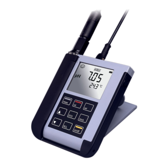
Page 10: Display
Overview of the Portavo 904X MULTI Display The meter has a three-line display for showing alphanumeric information such as measurement and calibration data, temperatures, and date/time. Additional information is provided by means of icons (Sensoface, battery icon, etc.). Some typical displays are shown here. -
Page 11: Keypad
Overview of the Portavo 904X MULTI Keypad The keys of the membrane keypad have a noticeable pressure point. They have the following functions: on/off Switches the meter on and displays the device and calibration data (see Start-up) meas Switches the meter on /... -
Page 12: Commissioning
• Only open the battery compartment of the Portavo 904X outside the hazardous location. • The device cannot be repaired by users. For inquiries regarding repairs, please contact Knick Elektronische Messgeräte GmbH & Co. KG at www.knick.de. • Never use the USB port within the hazardous location. Inserting the Batteries With four AA batteries, the Portavo has an operating time of over 1000 h. -
Page 13: Batteries For Application In Hazardous Locations
WARNING! Impairment of explosion protection. When using the Portavo 904X MULTI in a hazardous location, only the battery types listed below may be used. The batteries must be from the same manufactur‑ er and of identical type and capacity. Never use new and used batteries together (see also Control Drawing 209.009‑110). -
Page 14: Connecting A Sensor
Commissioning Connecting a Sensor The Portavo 904X MULTI provides several connections so that many types of sensors can be used for measurement (see illustration below). Note that only one sensor may be connected to the meter at a time. The meter recognizes the connected Mem- osens sensor and displays the Memosens logo. -
Page 15: Switching On The Meter
Commissioning Switching On the Meter The meter can be switched on by pressing the meas or on/off key. If you press meas, the meter immediately switches to measuring mode. After pressing the on/off key, the meter displays selected sensor information, incl. adjustment data, before it switches to measuring mode. -
Page 16: Configuration
(Option 001) | ORP OFFSET (for ORP or pH/ORP combo sen- sors) | TEMP. OFFSET (Option 001) | FREE CAL 1 | 2 | 3 | 1-2-3 (for CALIMATIC, Manual, FREE CAL) -01- Mettler-Toledo 2.00|4.01|7.00|9.21 -02- Knick CaliMat 2.00|4.00|7.00|9.00|12.00 -03- Ciba (94) 2.06|4.00|7.00|10.00 -04- NIST Technical 1.68|4.00|7.00|10.01|12.46... -
Page 17: Conductivity Configuration
Configuration Cond Conductivity Configuration Prior to measurement, a configuration should be performed to match the connected sensor and the desired measurement performance. Furthermore, you can select the suitable calibration method. The following table gives you an overview. Factory settings are shown in bold print. -
Page 18: Oxygen Configuration
Configuration Oxygen Configuration Configuration is required to match the connected sensor and the desired measurement performance. Furthermore, you can select the suitable calibration method. The following table gives you an over- view. Factory settings are shown in bold print. Measurement “SETUP”... -
Page 19: Ph Calibration
pH Calibration CALIMATIC Calibration (Calibration with automatic buffer recognition) The calibration method is selected in the configuration menu. Calibration is required to adjust the sensor to the meter. It is indis‑ pensable for achieving comparable and reproducible measurement results. Measurement Calibration method, the number of calibration points and CALIMATIC the buffer set have been selected in the configuration... - Page 20 pH Calibration MANUAL Calibration (Manual calibration) The calibration method is selected in the configuration menu. Measurement The number of calibration points has been MANUAL selected in the configuration menu. CAL 1/2/3 PRESS CAL pH display blinks Take the temperature‑corrected pH value from PRESS CAL the buffer description and enter it using ...
- Page 21 pH Calibration DATA INPUT Calibration (Calibration by entering known sensor values) The calibration method is selected in the configuration menu. Measurement DATA INPUT ZERO POINT Use to select the zero point value. SLOPE Use to select the slope value. The calibration data will be displayed successively: Date and time ZERO POINT...
- Page 22 pH Calibration ISFET Calibration – available if an ISFET sensor is connected The calibration method is selected in the configuration menu. When using ISFET sensors for pH measurement, the individual operating point of the sensor first needs to be determined, and should be in the pH 6.5...pH 7.5 range. The sensor is immersed in a buffer solution with a pH value of 7.00 for this purpose.
- Page 23 pH Calibration CAL SOP Calibration (Option, must have been configured in Paraly SW 112 PC software) In the Paraly SW 112 PC software, you specify which buffers are to be used in which sequence. You can combine buffer solutions from different buffer sets. Please note that the minimum distance allowed between two buffer solutions is Δ 2 pH.
- Page 24 pH Calibration ORP OFFSET Calibration (available if an ORP or pH/ORP combo sensor is connected) Selected in the configuration menu. Measurement You can specify an offset for the ORP value mea‑ sured by the sensor. ORP OFFSET After calibration has been activated, the follow‑ ing values are listed in the display: •...
- Page 25 pH Calibration TEMP. OFFSET Calibration (option) Temperature calibration (offset) Selected in the configuration menu. Measurement You can specify an offset for the temperature measured by the sensor. TEMP. OFFSET After calibration has been activated, the follow‑ ing values are listed in the display: •...
- Page 26 pH Calibration FREE CAL Calibration (Free selection of calibration method) FREE CAL calibration is selected in the configuration menu. Measurement Use to select the required calibration CALIMATIC blinks method (CALIMATIC, MANUAL, DATA INPUT, ISFET‑Zero, CAL SOP (Option 001), ORP OFFSET (for ORP or pH/ORP combo sensors), or TEMP.
-
Page 27: Conductivity Calibration
Conductivity Calibration Cond CELL CONST. Calibration (Calibration by entry of cell constant) The calibration method is selected in the configuration menu. Measurement The conductivity will be shown in the display CELL CONST. and can be compared with a reference solution (temperature‑corrected). - Page 28 Conductivity Calibration Cond 0.1/0.01 MOL KCL Calibration (Automatic calibration with KCl solution) The calibration method is selected in the configuration menu. Important notes: • Make sure that the values of the calibration solutions used correspond exactly to those specified in this manual. If not, the resulting cell constant will be incorrect.
- Page 29 Conductivity Calibration Cond INST. FACTOR calibration (For inductive conductivity measurement only or with Memosens 4-electrode sensor with specification of installation factor) Selected in the configuration menu. Measurement In narrow installation conditions, the conductivity INST. FACTOR measurement is influenced by the sensor’s dis‑ tance to the wall and the wall material.
- Page 30 Conductivity Calibration Cond ZERO POINT Calibration (For inductive conductivity measurement only: calibrating the sensor zero point) Calibration method is selected in the configuration menu. Measurement Remove the sensor for calibration and place it in air – then start calibration. ZERO POINT The “hourglass”...
- Page 31 Conductivity Calibration Cond TEMP. OFFSET Calibration (option) Temperature calibration (offset) Selected in the configuration menu. Measurement You can specify an offset for the temperature measured by the sensor. TEMP. OFFSET After calibration has been activated, the follow‑ ing values are listed in the display: •...
- Page 32 Conductivity Calibration Cond FREE CAL Calibration (Free selection of calibration method) FREE CAL calibration is selected in the configuration menu. Measurement Use to select a calibration method (de‑ CELL CONST. blinks pending on the connected sensor: CELL CONST., COND, 0.01 MOL KCL, 0.1 MOL KCL, INST. FAC‑ TOR, ZERO POINT, TEMP.
-
Page 33: Oxygen Calibration
Oxygen Calibration AIR CAL Calibration (Calibrating the slope in air) The calibration method is selected in the configuration menu. Measurement Place sensor in air and wait until the measured AIR CAL values have stabilized. Measured value Use to set the correct relative humidity Temperature value. - Page 34 Oxygen Calibration ZERO CAL Calibration (Zero calibration with oxygen-free medium) The calibration method is selected in the configuration menu. Measurement ZERO CAL Place sensor in oxygen‑free medium (e.g., nitrogen 5.0) and wait until the measured PRESS CAL blinks values have stabilized. CAL DATA Calibration is performed.
- Page 35 Oxygen Calibration DATA INPUT Calibration (Calibration by entering known sensor values) The calibration method is selected in the configuration menu. Measurement DATA INPUT xx blinks Use to set the known value for the sensor zero point. ZERO POINT xxx blinks Use ...
- Page 36 Oxygen Calibration TEMP. OFFSET Calibration (option) Temperature calibration (offset) Selected in the configuration menu. Measurement You can specify an offset for the temperature measured by the sensor. TEMP. OFFSET After calibration has been activated, the follow‑ ing values are listed in the display: •...
- Page 37 Oxygen Calibration FREE CAL Calibration (Free selection of calibration method) FREE CAL calibration is selected in the configuration menu. Measurement Use to set the required calibration method AIR CAL blinks (AIR CAL, ZERO CAL, DATA INPUT). Perform the selected calibration as described on the previous pages.
-
Page 38: Measurement
Measurement Oxy Cond Once you have completed all preparations , you can start with Keys for the actual measurement. measurement 1) Connect the desired sensor to the meter. Some sensors require a special preparation. Information on this can be found in the sensor’s user manual. 2) Switch the meter on using the on/off or meas key. -
Page 39: Data Logger
Data Logger Oxy Cond The Data Logger The meter provides a data logger. Prior to use, it must be configured and then acti- vated. You can choose from the following logger types: • DIFF (signal-controlled logging of measured variable and temperature) •... -
Page 40: Operating Modes Of The Data Logger (Logger Type)
Data Logger Oxy Cond Operating Modes of the Data Logger (Logger Type) Manual Logging when Logger is Activated (SHOT) In this mode, a measured value is recorded each time the STO key is pressed. Measurement Logger activated The measured value is saved to the address of the last recorded value + 1 Manual Logging when Logger is Deactivated Measurement Logger deactivated... - Page 41 Data Logger Oxy Cond Difference (DIFF) When the delta range (process variable and/or temperature) related to the last entry is exceeded, a new entry is created and the delta range is displaced upwards or downwards by the delta value. The first entry is automatically created when the data logger is started.
-
Page 42: Data Logger Menu
Data Logger Oxy Cond Data Logger Menu Select using arrow keys, confirm by pressing set. Logger view CONT Select start address and start the data logger START Deletes all entries and starts the data logger at start address 0001 Deletes all entries Selects and configures logger type (see table below) Configuring the Data Logger... -
Page 43: Configuring The Logger Type
Data Logger Oxy Cond Configuring the Logger Type Logger Select (default in bold print) type DIFF Logger LIQU: type OFF | 0.1 … 100.0 % air | 1.0 % air Delta % air OFF | 0.01 … 20.00 mg/l | 1.00 mg/l Delta mg/l GAS: OFF | 0.001 …... -
Page 44: Starting The Data Logger Using Cont
Data Logger Oxy Cond Starting the Data Logger using CONT Prerequisite: Data logger is configured. Every time the meter has been switched off, the data logger must be restarted (exception: SHOT). Measurement Measured value is maintained Logger: CONT blinks Address of the last recorded If desired: Select a start address using . -
Page 45: Displaying The Logger Data
Data Logger Oxy Cond Displaying the Logger Data Pressing the RCL key displays all stored values. The Paraly SW 112 PC software allows convenient management of the data logger. Measurement The “RCL” icon and the last Use to select the desired address. recorded value is displayed. -
Page 46: Stopping The Data Logger
Data Logger Oxy Cond Stopping the Data Logger You can stop the data logger at any time by pressing the meas key. Measurement, logger activated meas Data logger is stopped. “LOGGER” and “active logger type” icons are no longer displayed. It is still possible to hold a measured value by pressing STO and send it to any desired address. -
Page 47: Clock
Clock Press the clock key to access the clock mode. Date and time will be displayed in the format as set in the configuration menu. To set the clock, proceed as follows: Display of time+date Hour display blinks Set value. SET HOUR Minute display blinks Set value. -
Page 48: Options
Options Option 001 SOP (Standard Operating Procedure) Scope: Cal SOP Calibration Method The calibration method must be configured using the Paraly SW 112 PC software. Here, you specify which buffers are to be used in which sequence. You can combine buffer solutions from different buffer sets. -
Page 49: Enabling Options / Tan Input
Options Enabling Options / TAN Input When you have bought an option, you receive a document with a code (TAN) for enabling this option on your device. Press the set key to access the configuration mode. Use the arrow keys to select the “TAN TEMP CAL” function, for exam- ple, where you can enter the TAN for enabling the option. -
Page 50: Access Codes For Conf, Cal, And Data Logger
Options Access Codes for CONF, CAL, and Data Logger (with Option 001 SOP only) Press the set key to access the configuration mode. Use the arrow keys to select the “SETUP CODE” function and set an access code for configuration, “CAL CODE” to set an access code for calibration, and/or “LOGGER CODE”... -
Page 51: Inputting The Rescue Tan
The manufacturer can generate a rescue TAN (TAN RESCUE). For this purpose, please have the serial number of the corresponding device to hand. If you have any questions, please contact Knick Elektronische Messgeräte GmbH & Co. KG using the contact details provided on the last page of this document. -
Page 52: Paraly Sw 112 Pc Software
Make the following backups prior to upgrading or downgrading: • Read out Portavo data logger. • Save the Portavo device configuration in Paraly. The Paraly SW 112 PC software, incl. a detailed user manual, can be downloaded from www.knick.de. -
Page 53: Error And Status Messages
Error and Status Messages Oxy Cond Error messages are indicated as “ERROR …” on the display. Information on the sensor condition is indicated by the “Sensoface” icon (friendly, neutral, sad) possibly accom- panied by an info message (“INFO …”). Example of an error message: Example of a “Sensoface”... -
Page 54: Sensoface" Messages
Error and Status Messages Oxy Cond “Sensoface” Messages The “Sensoface” icon provides information on the sensor condition: Sensoface Meaning Sensor is okay Calibrate the sensor soon Calibrate or replace the sensor The “neutral” and “sad” Sensoface icons are accompanied by an “INFO …” message to give a hint to the cause of deterioration. -
Page 55: Error Messages
Error and Status Messages Oxy Cond Error Messages The following error messages can be shown in the display. Message Cause Remedy blinks Battery empty Replace batteries ERROR 1 Value out of range Check whether the measurement ERROR 2 ORP value out of range conditions correspond to the adjusted ERROR 3 Temperature value out of... -
Page 56: Product Line
Cal SOP calibration method: user management, sensor verifica- SW-P001 tion, temperature detector adjustment in the Memosens sensor (offset correction) Temperature detector adjustment in the Memosens sensor SW-P002 (offset correction) Paraly SW112 PC software for configuration and firmware updates: Free download from www.knick.de... - Page 57 Product Line Digital pH Sensors (Memosens) Please visit our website for more information on our product range: www.knick.de. Knick CaliMat (pH) Buffer Solutions Ready-to-Use Quality pH Buffer Solutions pH Value (20 °C/68 °F) Quantity Order No. 2.00 250 ml CS-P0200/250 4.00...
- Page 58 Conductivity Product Line Cond Digital Conductivity Sensors (Memosens) Please visit our website for more information on our product range: www.knick.de. Conductivity Standards for determining a cell constant Ready-to-Use Solutions Quantity Order No. 1.3 µS/cm, KCl 300 ml ZU0701 15 µS/cm, KCl...
- Page 59 Oxygen Product Line Digital Oxygen Sensors (Memosens) Please visit our website for more information on our product range: www.knick.de. Accessories for Oxygen Item Order No. Sensor protection for process sensors with Ø 12 mm and ZU1121 PG 13.5 thread made of PVDF...
-
Page 60: Specifications
Specifications Oxy Cond Connections 1 x M8 socket, 4 pins, for Memosens sensors 1 x M12 socket, 8 pins, for Memosens sensors 2 x 4-mm socket for separate temperature detector 1 x micro USB-B for data transmission to PC Be sure to observe the safety instructions when using the USB port. Display LCD STN 7-segment display with 3 lines and icons Sensoface... - Page 61 Specifications Oxy Cond RoHS conformity According to directive 2011/65/EU Power supply 4x AA batteries For battery types, see Control Drawing No. 209,009-110 Operating time Approx. 500 h (alkaline) Rated operating conditions Ambient temperature -10 °C ≤ Ta ≤ +40 °C Duracell MN1500 -10 °C ≤...
- Page 62 (TAN option) probe adjustment in the Memosens sensor (offset correction) FREE CAL Free selection of calibration method Calimatic buffer sets * -01- Mettler-Toledo 2.00/4.01/7.00/9.21 -02- Knick CaliMat 2.00/4.00/7.00/9.00/12.00 -03- Ciba (94) 2.06/4.00/7.00/10.00 -04- NIST technical 1.68/4.00/7.00/10.01/12.46 -05- NIST standard 1.679/4.006/6.865/9.180 -06- HACH 4.01/7.00/10.01/12.00...
- Page 63 Specifications Permissible calibration ranges Zero point 6 ... 8 pH For ORP sensor: ΔmV (offset) -700 … 700 mV With ISFET: -750 … 750 mV Operating point (asymmetry) Slope Approx. 74 … 104 % (possibly restricting notes from Sensoface) Calibration timer * Interval 1 …...
- Page 64 Specifications Cond Conductivity input, M8 socket, 4-pin or Memosens M12 socket, 8-pin Measuring range SE 615/1-MS sensor: 10 µS/cm … 20 mS/cm For other sensors, see the sensor documentation. Measuring cycle Approx. 1 s Display resolution Conductivity 0.001 μS/cm (c < 0.05 cm –1 (autoranging) 0.01 μS/cm (c = 0.05 …...
- Page 65 Specifications Cond Concentration -01- NaCl 0 – 26 wt% (0 °C / 32 °F) ... 0 – 28 wt% (100 °C /+212 °F) determination -02- HCl 0 – 18 wt% (–20 °C / –4 °F) ... 0 – 18 wt% (50 °C /122 °F) -03- NaOH 0 –...
- Page 66 Specifications Memosens input, oxygen M8 socket, 4-pin or M12 socket, 8-pin Display ranges Saturation 0.000 … 200.0 % Concentration 000 μg/l … 20.00 mg/l 0.000 … 100.0 % Temperature meas. range -20 ... 150 °C / -4 ... 302 °F Sensor adjustment Operating modes * AIR CAL...
-
Page 67: Buffer Tables
Buffer Tables -01- Mettler-Toledo Nominal values in bold. °C... - Page 68 Buffer Tables -02- Knick CaliMat Nominal values in bold. °C...
- Page 69 Buffer Tables -03- Ciba (94) Nominal values: 2.06 4.00 7.00 10.00 °C 1) extrapolated...
- Page 70 Buffer Tables -04- Technical Buffers to NIST Nominal values in bold. °C 1) values added...
- Page 71 Buffer Tables -05- NIST Standard (DIN 19266: 2015-05) Nominal values in bold. °C Note: The actual pH(S) values of the individual batches of the reference materials are documented in a certificate of an accredited laboratory. This certificate is supplied with the respective buffers. Only these pH(S) values shall be used as standard values for the secondary reference buffer materials.
- Page 72 Buffer Tables -06- HACH Nominal values: 4.01 7.00 10.01 (± 0.02 at 25 °C) °C...
- Page 73 Buffer Tables -07- WTW Technical Buffers Nominal values in bold. °C...
- Page 74 Buffer Tables -08- Hamilton Nominal values in bold. °C...
- Page 75 Buffer Tables -09- Reagecon Nominal values in bold. °C 1) values added...
- Page 76 Buffer Tables -10- DIN 19267 Nominal values in bold. °C 1) extrapolated...
-
Page 77: Index
Index 0.01 or 0.1 mol KCl calibration (Cond) 28 0000 DELETED (“data deleted” display) 46 AA batteries 12 Access codes (option) 48 Accessories for Cond 58 Accessories for Oxy 59 Accessories for pH 57 Accessories/options 56 AIR CAL (Oxy calibration) 33 Altitude (Oxy configuration) 18 Arrow keys 11 Automatic calibration (Cond) 28... - Page 78 Index Commissioning 12 Conductivity calibration, 0.1/0.01 MOL KCL 28 Conductivity calibration, CELL CONST 27 Conductivity calibration, entry of solution 27 Conductivity calibration, FREE CAL 32 Conductivity calibration, INST. FACTOR 29 Conductivity calibration, TEMP. OFFSET (Option) 31 Conductivity calibration, ZERO POINT 30 Conductivity configuration 17 Conductivity standards, product line 58 Configuration, access control 48...
- Page 79 Inserting the batteries 12 Installation factor, calibration 29 Intended Use 7 Interfaces 14 Interrupting the data logger 46 Interval (data logger mode) 40 Introduction 7 ISFET calibration 22 KCl solution (Cond calibration) 28 Keypad 11 Knick CaliMat buffer solutions 57...
- Page 80 Index Laboratory cable for Memosens sensors 56 Logger 39 LOGGER CODE 48 Logger type, configuration 43 Logger type (data logger modes) 40 Manual calibration (Cond) 27 Manual calibration (pH) 20 meas key 11 meas, switch-on 15 Measured-value recording 40 Measuring 38 Memory for measured values 39 Memosens 8 Memosens cable (accessory) 56...
- Page 81 Index Order numbers (pH) 56 ORP calibration 24 ORP OFFSET calibration 24 Overview 7 Overview of Cond configuration 17 Overview of error messages 55 Overview of Oxy configuration 18 Overview of pH Configuration 16 Oxy configuration 18 Oxygen calibration, AIR CAL 33 Oxygen calibration, DATA INPUT 35 Oxygen calibration, FREE CAL 37 Oxygen calibration, TEMP.
- Page 82 Index RCL, displaying the logger data 45 RCL key 11 Real-time clock 7 Recorded data, display 45 Repair 3 Replacement quiver 56 Rescue TAN 51 Returns 3 Safety Instructions 6 Saving the currently measured value 40 Seconds, display 47 Sensoface messages 54 Sensor check (option) 48 Sensor connection 14 Sensors 14...
- Page 83 Index Stopping the data logger 46 Structure of data logger 42 Suspending the meter 9 Switching on the meter 15 Switching the measurement display 38 Symbols in display 15 T3, temperature class 13 T4, temperature class 13 Table of Cond configuration 17 Table of error messages 55 Table of Oxy configuration 18 Table of pH configuration 16...
- Page 84 Knick Elektronische Messgeräte GmbH & Co. KG Headquarters Beuckestraße 22 • 14163 Berlin Germany Phone: +49 30 80191-0 Fax: +49 30 80191-200 info@knick.de www.knick.de Local Contacts www.knick-international.com Copyright 2021 • Subject to change Version: 2 This document was last updated on March 31, 2021 The latest documents are available for download on our website under the corresponding product description.
Need help?
Do you have a question about the Portavo 904X MULTI and is the answer not in the manual?
Questions and answers