
Subscribe to Our Youtube Channel
Related Manuals for Knick Portavo 904 OXY


Summary of Contents for Knick Portavo 904 OXY
- Page 1 Portavo® 904 OXY User Manual Portable Meter Read before installation. Keep for future use. www.knick.de...
- Page 3 Knick Elektronische Messgeräte GmbH & Co. KG at www.knick.de. Returns Clean and securely package the product before returning it to Knick Elektronische Messgeräte GmbH & Co. KG. If there has been contact with hazardous substances, the product must be de- contaminated or disinfected prior to shipment.
-
Page 4: Table Of Contents
Table of Contents Package Contents ................6 Overview of the Portavo 904 OXY ............ 7 Intended Use ........................7 Value-Added Features ....................8 Protective Cover ......................9 Hook ..........................9 Display ......................... 10 Keypad ........................11 Commissioning ................. 12 Inserting the Batteries ................... 12 Connecting a Sensor .................... - Page 5 Table of Contents Options ....................31 Option 001 SOP (Standard Operating Procedure) ........31 Option 002 TEMP.CAL (Temperature Calibration) ........31 Enabling Options / TAN Input ................32 Access Codes for CONF, CAL, and Data Logger ..........33 Inputting the Rescue TAN ..................34 Paraly SW 112 PC Software ..............
-
Page 6: Package Contents
• Quickstart overview for attaching to the inside of the protective cover (German, English, French) • Safety guide • Quickstart instructions in various languages • Test report 2.2 according to EN 10204 User manuals, the Paraly SW 112 PC software, and other product information can be downloaded from www.knick.de. -
Page 7: Overview Of The Portavo 904 Oxy
Overview of the Portavo 904 OXY Intended Use The Portavo 904 OXY is a portable oxygen meter. With a plain text line on a high-contrast LCD, operation is largely intuitive. The meter stands out by the following features: • Use of digital Memosens sensors •... -
Page 8: Value-Added Features
Overview of the Portavo 904 OXY Value-Added Features Memosens The Portavo 904 can communicate with Memosens sensors. These digital sensors are automatically identified and the meter switches to the appropriate measurement method. When a Memosens sensor is connected to the meter, it is indicated by the logo shown on the right. -
Page 9: Protective Cover
Overview of the Portavo 904 OXY Protective Cover The front of the meter is protected by a cover, which can be completely flipped over and secured to the back for oper- ation. A label on the inner side of the cover explains the control functions and device messages. -
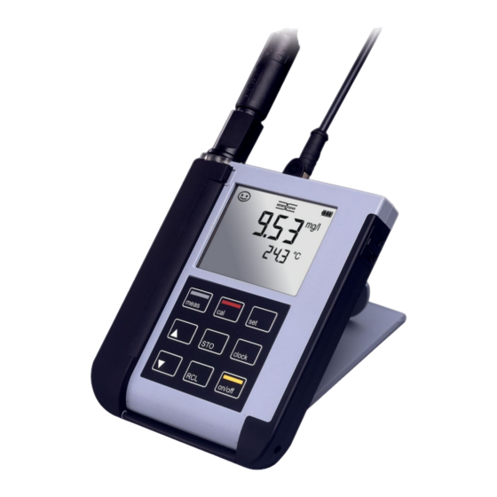
Page 10: Display
Overview of the Portavo 904 OXY Display The meter has a three-line display for showing alphanumeric information such as measurement and calibration data, temperatures, and date/time. Additional information is provided by means of icons (Sensoface, battery icon, etc.). Some typical displays are shown here. -
Page 11: Keypad
Overview of the Portavo 904 OXY Keypad The keys of the membrane keypad have a noticeable pressure point. They have the following functions: on/off Switches the meter on and displays the device and calibration data (see Start-up) meas Switches the meter on /... -
Page 12: Commissioning
Commissioning Check the shipment for transport damage and completeness (see Package Contents). CAUTION! Do not operate the device when one of the following conditions applies: • the device shows visible damage • failure to perform the intended function • prolonged storage at temperatures above 70 °C / 158 °F •... -
Page 13: Connecting A Sensor
Commissioning Connecting a Sensor The Portavo 904 OXY provides several connections so that many types of sensors can be used for measurement (see illustration below). Note that only one sensor may be connected to the meter at a time. The meter recognizes the connected Memosens sensor and displays the Memosens logo. -
Page 14: Switching On The Meter
Commissioning Switching On the Meter When you have connected the sensor, you can switch on the meter by pressing the meas or on/off key. If you press meas, the meter immediately switches to measuring mode. After pressing the on/off key, the meter displays selected sensor information, incl. -
Page 15: Configuration
Configuration Press the set key to access configuration mode. Prior to measurement, a configuration should be performed to match the connected sensor and the desired measurement performance. Furthermore, you can select the suitable calibration method. The following table gives you an overview. Factory settings are shown in bold print. -
Page 16: Calibration
Calibration AIR CAL Calibration (Calibrating the slope in air) The calibration method is selected in the configuration menu. Measurement Place sensor in air and wait until the measured AIR CAL values have stabilized. Measured value Use to set the correct relative humidity Temperature value. - Page 17 Calibration ZERO CAL Calibration (Zero calibration with oxygen-free medium) The calibration method is selected in the configuration menu. Measurement ZERO CAL Place sensor in oxygen-free medium (e.g., nitrogen 5.0) and wait until the measured PRESS CAL blinks values have stabilized. CAL DATA Calibration is performed.
- Page 18 Calibration DATA INPUT Calibration (Calibration by entering known sensor values) The calibration method is selected in the configuration menu. Measurement DATA INPUT xx blinks Use to set the known value for the sensor zero point. ZERO POINT xxx blinks Use ...
- Page 19 Calibration TEMP. OFFSET OFFSET (option) Temperature calibration (offset) Selected in the configuration menu. Measurement You can specify an offset for the temperature measured by the sensor. TEMP. OFFSET After calibration has been activated, the follow- ing values are listed in the display: •...
- Page 20 Calibration FREE CAL Calibration (Free selection of calibration method) FREE CAL calibration is selected in the configuration menu. Measurement Use to set the required calibration method AIR CAL blinks (AIR CAL, ZERO CAL, DATA INPUT). Perform the selected calibration as described on the previous pages.
-
Page 21: Measuring
Measuring Keys for Once you have completed all preparations, you can start with measurement the actual measurement. 1) Connect the desired sensor to the meter. Some sensors require a special preparation. Please proceed according to the operating instructions for the sensor. 2) Switch the meter on using the on/off or meas key. -
Page 22: Data Logger
Data Logger The Data Logger The meter provides a data logger. Prior to use, it must be configured and then acti- vated. You can choose from the following logger types: • DIFF (signal-controlled logging of measured variable and temperature) • INT (time-controlled logging at a fixed interval) •... -
Page 23: Operating Modes Of The Data Logger (Logger Type)
Data Logger Operating Modes of the Data Logger (Logger Type) Manual Logging when Logger is Activated (SHOT) In this mode, a measured value is recorded each time the STO key is pressed. Measurement Logger activated The measured value is saved to the address of the last recorded value + 1 Manual Logging when Logger is Deactivated Measurement Logger deactivated... - Page 24 Data Logger Difference (DIFF) When the delta range (process variable and/or temperature) related to the last entry is exceeded, a new entry is created and the delta range is displaced upwards or downwards by the delta value. The first entry is automatically created when the data logger is started.
-
Page 25: Data Logger Menu
Data Logger Data Logger Menu Select using arrow keys, confirm by pressing set. Logger view CONT Select start address and start the data logger START Deletes all entries and starts the data logger at start address 0001 Deletes all entries Select logger type and configure: DIFF, INT, DIF- F+INT, SHOT (see table below) Configuring the Data Logger... -
Page 26: Configuring The Logger Type
Data Logger Configuring the Logger Type Logger Select (default in bold print) type DIFF LIQU: OFF | 0.1 … 100.0 % air | 1.0 % air Delta % air Delta mg/l OFF | 0.01 … 20.00 mg/l | 1.00 mg/l GAS: OFF | 0.001 …... -
Page 27: Starting The Data Logger Using Cont
Data Logger Starting the Data Logger using CONT Prerequisite: Data logger is configured. Every time the meter has been switched off, the data logger must be restarted (exception: SHOT). Measurement Measured value is maintained Logger: CONT blinks Address of the last recorded value + If desired: Select a start address using . -
Page 28: Displaying The Logger Data
Data Logger Displaying the Logger Data Pressing the RCL key displays all stored values. The Paraly SW 112 PC software allows convenient management of the data logger. Measurement The “RCL” icon and the last record- Use to select the desired address. ed value is displayed. -
Page 29: Stopping The Data Logger
Data Logger Stopping the Data Logger You can stop the data logger at any time by pressing the meas key. Measurement, logger activated meas Data logger is stopped. “LOGGER” and “active logger type” icons are no longer displayed. It is still possible to hold a measured value by pressing STO and send it to any desired address. -
Page 30: Clock
Clock Press the clock key to access the clock mode. Date and time will be displayed in the format as set in the configuration menu. To set the clock, proceed as follows: Display of time+date Hour display blinks Set value. SET HOUR Minute display blinks Set value. -
Page 31: Options
Options Option 001 SOP (Standard Operating Procedure) Scope: Sensor Verification The Paraly SW 112 PC software allows a sensor to be assigned to the device. See the Paraly SW 112 PC software user manual. Setup / Cal / Logger Code Access codes can be set on the meter or using the Paraly SW 112 PC software;... -
Page 32: Enabling Options / Tan Input
Options Enabling Options / TAN Input When you have bought an option, you receive a document with a code (TAN) for enabling this option on your device. Press the set key to access the configuration mode. Use the arrow keys to select the “TAN TEMP CAL” function, for exam- ple, where you can enter the TAN for enabling the option. -
Page 33: Access Codes For Conf, Cal, And Data Logger
Options Access Codes for CONF, CAL, and Data Logger (with Option 001 SOP only) Press the set key to access the configuration mode. Use the arrow keys to select the “SETUP CODE” function and set an access code for configuration, “CAL CODE” to set an access code for calibration, and/or “LOGGER CODE”... -
Page 34: Inputting The Rescue Tan
The manufacturer can generate a rescue TAN (TAN RESCUE). For this purpose, please have the serial number of the corresponding device to hand. If you have any questions, please contact Knick Elektronische Messgeräte GmbH & Co. KG using the contact details provided on the last page of this document. -
Page 35: Paraly Sw 112 Pc Software
Make the following backups prior to upgrading or downgrading: • Read out Portavo data logger. • Save the Portavo device configuration in Paraly. The Paraly SW 112 PC software, incl. a detailed user manual, can be downloaded from www.knick.de. -
Page 36: Error And Status Messages
Error and Status Messages Error messages are indicated as “ERROR …” on the display. Information on the sensor condition is indicated by the “Sensoface” icon (friendly, neutral, sad) possibly accom- panied by an info message (“INFO …”). Example of an error message: Example of a “Sensoface”... -
Page 37: Sensoface" Messages
Error and Status Messages “Sensoface” Messages The “Sensoface” icon provides information on the sensor condition: Sensoface Meaning Sensor is okay Calibrate the sensor soon Calibrate or replace the sensor The “neutral” and “sad” Sensoface icons are accompanied by an “INFO …” message to give a hint to the cause of deterioration. -
Page 38: Error Messages
Error and Status Messages Error Messages The following error messages can be shown in the display. Cause Message Remedy Battery empty Replace the batteries. blinks ERROR 1 Value out of range Check whether the measurement conditions correspond to the ERROR 3 Temperature value out of adjusted measuring range. -
Page 39: Product Line
Product Line Sensors Digital Oxygen Sensors Order No. Oxygen sensor with Memosens connector, 120 mm SE715/1-MS Accessories/Options Item Order No. Robust field case (for meter, sensor, ZU0934 various small parts and user manual) Li-ion battery ZU0925 Replacement quiver (5 units) ZU0929 Adapter for process sensors with Ø... - Page 40 SOP (Standard Operating Procedure): user management, sensor SW-P001 verification, temperature detector adjustment in the Memosens sensor (offset correction) Temperature detector adjustment in the Memosens sensor SW-P002 (offset correction) Paraly SW112 PC software for configuration and firmware updates: Free download from www.knick.de...
-
Page 41: Specifications
Specifications Memosens input, oxygen M8 socket, 4-pin or M12 socket, 8-pin Display ranges Saturation 0.000 … 200.0 % Concentration 000 μg/l … 20.00 mg/l 0.000 … 100.0 % Temperature meas. range -20 … 150 °C / -4 … 302 °F Sensor adjustment Operating modes * AIR CAL... - Page 42 Specifications RoHS conformity According to directive 2011/65/EU Power supply Portavo 904 4x AA alkaline batteries or 4x rechargeable NiMH batteries 1x Li-ion battery, USB chargeable Operating time Approx. 500 h (alkaline) Rated operating conditions Ambient temperature -10 °C … 55 °C/ 14 … 122 °F Transport/ -25 …...
-
Page 43: Index
Index 0000 DELETED (“data deleted” display) 29 AA batteries 12 Access codes (option) 31 Accessories 39 AIR CAL (calibration) 16 AIR CAL calibration 16 Altitude (configuration) 15 Arrow keys 11 Base stand (accessory) 39 Battery capacity 12 Battery compartment 12 Battery icon 12 Battery replacement 12 Benchtop stand 9... - Page 44 Index DATA INPUT (calibration) 18 DATA INPUT calibration 18 Data Logger 22 Data logger, access control 31 Data logger configuration 25 Data logger menu 25 Data logger, stopping 29 Data memory 22 Data of the meter 41 Date 30 Default (configuration) 15 Deleting data logger entries 29 Delta range (data logger) 24 Device configuration 15...
- Page 45 Index Icons 14 Icons for data logger 22 INFO messages 37 Inserting the batteries 12 Interfaces 13 Interrupting the data logger 29 Interval (data logger mode) 23 Introduction 7 Keypad 11 Laboratory cable for Memosens sensors 39 Li-ion battery (accessory) 39 Lithium-ion battery 12 Logger 22 LOGGER CODE 31...
- Page 46 Index Nameplate 9 Nitrogen 5.0 17 O2 electrolyte (accessory) 39 on/off key 11 on/off, switch-on 14 Operating modes of the data logger 23 Option 001 SOP 31 Option 002 TEMP. OFFSET 31 Options, order codes 40 Options, overview 31 Options, TAN input 32 Order numbers (accessories) 39 Overview 7 Overview of configuration 15...
- Page 47 Index Replacement quiver (accessory) 39 Rescue TAN 34 Reset to factory settings 15 Returns 3 Safety Instructions 6 Saving the currently measured value 23 Seconds, display 30 Sensoface messages 37 Sensor check (option) 31 Sensor connection 13 Sensor protection (accessory) 39 Sensors 13 set key 11 Setting the configuration data 15...
- Page 48 Index Table of error messages 38 Table view of configuration 15 TAN input 32 Temperature calibration (TEMP. OFFSET, option) 19 Temperature detectors (accessory) 39 TEMP. OFFSET OFFSET (option) 19 Triangle icons 11 USB port (battery) 12 Value-added features 8 Viewing recorded data 28 Viewing the logger data 28 ZERO CAL calibration 17...
- Page 50 Knick Elektronische Messgeräte GmbH & Co. KG Headquarters Beuckestraße 22 • 14163 Berlin Germany Phone: +49 30 80191-0 Fax: +49 30 80191-200 info@knick.de www.knick.de Local Contacts www.knick-international.com Copyright 2021 • Subject to change Version: 2 This document was last updated on March 31, 2021 The latest documents are available for download on our website under the corresponding product description.
Need help?
Do you have a question about the Portavo 904 OXY and is the answer not in the manual?
Questions and answers