
Related Manuals for Mea SMAC 35DG/BFM


Summary of Contents for Mea SMAC 35DG/BFM
- Page 1 SMAC 35DG/BFM 15HP MINE SPEC Owner’s / Operator’s Manual 35 CFM Diesel Driven Air Compressor Revision: 12.1 Reviewed: 16/12/2021 7202-D0001-12...
- Page 2 THIS PAGE IS LEFT BLANK INTENTIONALLY. Document No 7202-D0001-12...
- Page 3 MEA Product Warranty Registration Form THIS FORM MUST BE COMPLETED AND RETURNED WITHIN 30 DAYS OF INSTALLATION WARRANTY WILL BE VOID Document No 7202-D0001-12...
- Page 4 CUT HERE MEA Product Warranty Registration Form This form must be completed and returned to MEA at the time of Installation. Warranty will be void if this form is not received by MEA within 30 days of installation. MEA Dealer Information...
-
Page 5: Table Of Contents
9. DRAWINGS & ILLUSTRATIONS ................ 21 TO 40 12. WARRANTY INFORMATION ................41 TO 42 Both the MEA Product Warranty Registration form (located at the FRONT of this Manual) and the Kubota Engine Warranty Registration form (located at the back of this manual) -
Page 6: Compressed Air Safety
Death and permanent disability are possibilities that can occur. The following are suggested as minimum requirements to be followed when operating the MEA SMAC system. It is important that each work site shall perform a risk analysis and produce a procedure to eliminate or control the hazardous condition to minimise the risk to personnel and equipment. -
Page 7: Introduction
2. INTRODUCTION This MEA (SMAC35DG BFM) Service Maintenance Air Compressor utilises a diesel engine to power the compressor and generator. Only those who have been trained and who have read and understand the operator and installation manual should operate and install the MEA (SMAC35DG BFM). This manual contains vital information on integrating the compressor system into the vehicle system and to ensure that it is installed and operated in a safe and efficient manner. - Page 8 INTRODUCTION - continued Document No 7202-D0001-12...
-
Page 9: Specifications
Rapid blow-down valve to discharge system pressure on shutdown Lubrication: All replacement compressor oils must be approved by MEA prior to use. Warranty will be nullified if oil has not been approved. MEA certified and approved semi synthetic compressor oil Part Number 10019 –... - Page 10 Engine Protection: Engine low oil pressure and high-coolant temperature sensors. MEA approved oil to meet strict emission control regulations, min. class “CF” Lubrication: or better is required. If oil does not meet the minimum requirements, all warranty will be nullified.
- Page 11 4. OPERATING PROCEDURES PRE-START CHECK EACH DAY Check the oil level in the engine. Check the water level in the engine. Check the oil level in the compressor Check all hoses are secured and not damaged. Replace all damaged hoses before starting. Check all electrical cables are secure.
- Page 12 OPERATING PROCEDURES - continued STARTING / STOPPING DIESEL ENGINE AND COMPRESSOR – NEW CONTROL BOX (INTRODUCED: 29/06/16) Note: Wiring harness has blue trace for ID. Not interchangeable to previous version i.e., key ignition starts. STARTING THE DIESEL ENGINE Check the COMPRESSOR ROCKER SWITCH is set to the OFF position (centre position). Press the ON/OFF/GLOW rocker switch to the LOWER POSITION –...
- Page 13 OPERATING PROCEDURES – continued If the escaping air is from a broken pipe or connection, turn the COMPRESSOR SWITCH to the OFF position. Stop the diesel engine. Advise the maintenance department for their assistance. The engine will reduce its RPM when the compressor reaches the pre-set regulated pressure. The compressor is now ready to be used.
-
Page 14: Installation
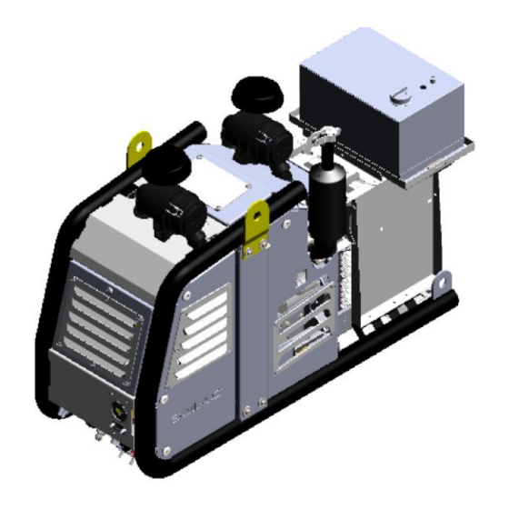
5. INSTALLATION SMACD unit consists of a rotary screw type driven by a diesel engine. Compression occurs when inlet air (at atmospheric pressure) enters a chamber where it is trapped between the rotating rotor lobes. A lubricated pitch line provides sealing. As the lobes mesh, they reduce the volume of the air, compressing it to the desired pressure. - Page 15 INSTALLATION - continued The information in this section is very important for proper operation of the compressor. Read these requirements before beginning installation. The following is a view of the compressor/diesel engine unit. Document No 7202-D0001-12...
- Page 16 INSTALLATION – continued General Consideration Mounting the Compressor Unit The starting point for the installation is a quick overview of the requirements. Some of these points will be dealt with in more detail further on in this text. Things that should be considered now are as follows. The unit should be installed in a well-ventilated area.
- Page 17 INSTALLATION - continued Setup and run the system at 120 PSI. This can be done by installing a ball valve on the air outlet pipe and adjusting the opening of the valve so that the compressor is running continuously at 120 PSI.
- Page 18 FRL is not able to cope with the moisture an AFTERCOOLER is installed onto the compressor unit. A An MEA water separator can be installed with electric solenoid operated drain valve part number Completing the Installation - Before Checking the System...
- Page 19 (idle speed). The Unit has been adjusted by the factory to the customer specification. If the pressure is not at the specified pressure, refer to MEA before attempting any adjustments.
-
Page 20: Schedule Maintenance
6. SCHEDULE MAINTENANCE The maintenance intervals recommended are based on standard operating conditions. The intervals for inspection, lubrication and maintenance given herein are maximum intervals and it should be noted to schedule the maintenance accordingly to sites. When is unit is being operated in a dusty environment, in high ambient temperatures or in other unusual conditions, an assessment needs to be done for shorter service interval? A planned program of periodic inspection and maintenance will help to avoid premature failure and costly repairs. - Page 21 SCHEDULE MAINTENANCE – continued Interval Compressor Diesel Engine Action to be taken Observe all gauge readings. Note any change from the normal reading and determine the Periodically During cause. Have the necessary repairs made? (Note: “Normal” is the usual gauge reading when Operation operating at similar conditions on a day-to-day basis.) Check the compressor oil level.
-
Page 22: Spare Parts And Service Kits
7. SPARE PARTS AND SERVICE KITS (SEE SERVICING SCHEDULE IN PREVIOUS SECTION) SERVICE KITS FOR CURRENT SPECIFICATION OF SMAC Code Description SERVICE KIT SMAC D/G 50HR – ENGINE ONLY 7201-KB0017 SERVICE KIT SMAC D/G 200HR – ENGINE ONLY 7201-KB0015 SERVICE KIT SMAC D/G 400HR – MINOR ENGINE & COMPRESSOR 7201-KB0013 7201-KB0028 SERVICE KIT SMAC D/G 800HR - MAJOR ENGINE &... - Page 23 8. TROUBLESHOOTING Document No 7202-D0001-12...
- Page 24 TROUBLESHOOTING - continued Document No 7202-D0001-12...
- Page 25 9. DRAWINGS & ILLUSTRATIONS GENERAL ARRANGEMENT DRAWING – GENERATOR CW BATTERY AND FUEL TANK Document No 7202-D0001-12...
- Page 26 DRAWINGS AND ILLUSTRATIONS PARTS LIST Document No 7202-D0001-12...
- Page 27 DRAWINGS & ILLUSTRATIONS PARTS LIST Document No 7202-D0001-12...
- Page 28 DRAWINGS & ILLUSTRATIONS PARTS LIST Document No 7202-D0001-12...
- Page 29 DRAWINGS & ILLUSTRATIONS PARTS LIST Document No 7202-D0001-12...
- Page 30 DRAWINGS & ILLUSTRATIONS HYDRAULIC/PNEUMATIC DIAGRAM Document No 7202-D0001-12...
- Page 31 DRAWINGS & ILLUSTRATIONS SMAC WIRING DIAGRAM (MINE SPEC) Document No 7202-D0001-12...
-
Page 32: Drawings & Illustrations
DRAWINGS & ILLUSTRATIONS Document No 7202-D0001-12... - Page 33 DRAWINGS & ILLUSTRATIONS Single Phase Electrical Outlet Circuit Diagram Document No 7202-D0001-12...
- Page 34 DRAWINGS & ILLUSTRATIONS Document No 7202-D0001-12...
- Page 35 MEA are defective. The obligation of MEA is limited to replacement of faulty parts. No liability is accepted for any freight costs, consequential damages, injuries, or expenses directly or indirectly related to the Product(s) failure.
- Page 36 WARRANTY (continued) BUYER OBLIGATIONS Buyer shall notify MEA of the alleged defect within 10 days of initial discovery and return the allegedly defective component(s) within 30 days of initial discovery. The Buyer must prepay all costs associated with the warranty.
- Page 37 MOBILE ENERGY AUSTRALIA - CONTACTS Sales Office: 07 3273 6803 Email: sales@mobileenergyaustralia.com.au Spare Parts Office: 07 3273 6803 Email: sales@mobileenergyaustralia.com.au Service Office: 07 3273 6803 Email: workshop@mobileenergyaustralia.com.au Document No 7202-D0001-12...
Need help?
Do you have a question about the SMAC 35DG/BFM and is the answer not in the manual?
Questions and answers