Table of Contents
Advertisement
Quick Links
INSTALLATION AND OPERATING MANUAL
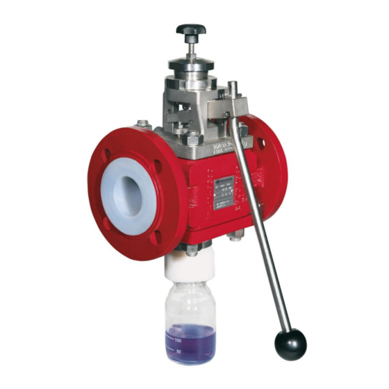
Series PA/F, PA/S
Sampling Valves
PFA-lining or
investment cast stainless steel
Keep for future use!
This operating manual must be strictly observed before
transport, installation, operation and maintenance
Subject to change without notice.
Reproduction is generally permitted with indication of the source.
© Richter Chemie-Technik GmbH.
9510-010-en Revision 18 Edition 11/2018
Advertisement
Table of Contents

Related Manuals for Richter PA/F Series


Summary of Contents for Richter PA/F Series
- Page 1 Keep for future use! This operating manual must be strictly observed before transport, installation, operation and maintenance Subject to change without notice. Reproduction is generally permitted with indication of the source. © Richter Chemie-Technik GmbH. 9510-010-en Revision 18 Edition 11/2018...
-
Page 2: Table Of Contents
Series PA/F, PA/S Page 2 List of Contents List of Contents ..........2 7 Operation ........... 10 Relevant documents ........3 7.1 Initial commissioning ........10 7.2 Improper operation and their consequences 1 Technical data ..........3 ..............10 1.1 Type plate and body markings ...... 4 7.3 Sampling (Standard)........ -
Page 3: Relevant Documents
♦ For PAP/F, PAP/S: Operating manual for actuator ♦ Manufacturer Declaration TA-Luft Technical data Manufacturer: Installation position : Richter Chemie-Technik GmbH The installation position is normally horizontal with the Otto-Schott-Str. 2 bottle connection vertically downwards (deviations D-47906 Kempen from this position require a special bottle connection). -
Page 4: Type Plate And Body Markings
Series PA/F, PA/S Page 4 Type plate and body markings Pipe screws, flanges ISO/DIN drilled to ASME Class 150 The stainless steel name plate is undetachably riveted Flange Tightening screws to the body. Nominal size torque If the operator attaches his identification, it must be en- [mm] [inch] [ASME] [in-lbs]... -
Page 5: Viscosity-Pressure Diagram
For valves which are used in potentially explosive ar- Intended use eas, see Section 3. Installation, operation and maintenance are to be per- Richter sampling valves are pressure-maintaining com- formed by qualified staff. ponents in accordance with the Pressure Equipment The area of responsibility, authority and supervision of Directive (DGRL) for taking liquid samples. -
Page 6: For The Customer / Operator
Series PA/F, PA/S Page 6 2.2 For the customer / operator 2.3 Improper operation If a valve is used, the operator must ensure that The operational reliability of the valve supplied is only guaranteed if it is used properly in accordance with ♦... -
Page 7: Safety Note For Valves, Certified To Clean Air Act (Ta Luft)
Series PA/F, PA/S Page 7 This means that, to safely prevent ignitions, the ♦ Increased wear to the valve can be expected with valve must be completely filled with medium at all the conveyance of liquids containing abrasive con- times or else a potentially explosive atmosphere stituents. -
Page 8: Transport, Storage And Disposal
Series PA/F, PA/S Page 8 Transport, storage and disposal For all transport work, observe generally 5.2 Return consignments accepted engineering practice and the ac- cident prevention regulations. Valves which have conveyed aggressive or toxic media must be well rinsed and The valve is supplied with flange caps. -
Page 9: Installation
These gaskets are availa- changed operating limits acc. to the name plate must ble as accessories in the Richter range. be observed and the travel must be set according to the setting instructions in Section 6.7. -
Page 10: Needle Adapter For Pa/S Dn25
Series PA/F, PA/S Page 10 Needle adapter for PA/S DN25 When you use a stainless steel needle adapter for PA/S DN25 make sure that you insert the flat gasket. Operation Initial commissioning Normally, the valves have been tested for Improper operation and their leaks with air or water. -
Page 11: Sampling (Standard)
♦ Press in direction of valve. ♦ Sampling can take place. A lock is available from Richter as an option. A device, screw fitting 917 for example, for the riskfree discharge of the medium must be connected to the venting connection. -
Page 12: Maintenance
Series PA/F, PA/S Page 12 Maintenance ♦ All repair work is to be performed by qualified per- ♦ Loosen setscrew 904 in spring bush 514. sonnel using the appropriate tools. ♦ For the arrangement, designation and item numbers of all parts of the valve, see Section 10. ♦... -
Page 13: Disassembling Pa/S And Removing The Packing Rings
Series PA/F, PA/S Page 13 ♦ Remove actuation 515 from cover 106. Disassembling PA/S and removing the packing rings ♦ Unscrew cap nut 927, remove disc 550 and bottle connection 226. ♦ Undo groove nut 509. Star grip 963 can remain screwed in. -
Page 14: Assembling Pa/F And Inserting The Packing Rings
Series PA/F, PA/S Page 14 ♦ Undo hex nuts 920 of cover 106. ♦ Remove thrust ring 405 from cover 106. ♦ Remove cover 106 and the stud screws 902. ♦ Remove packing rings 402. ♦ Turn cover 106 around and remove guide ring 302. ♦... - Page 15 Series PA/F, PA/S Page 15 ♦ Insert guide ring 302 from the bottom into cover 106, ♦ Insert actuation 515 into cover 106. and push the ring into the groove. ♦ Insert stem 855 and bellows 206 into cover 106. ♦...
-
Page 16: Assembling Pa/S And Inserting The Packing Rings
Series PA/F, PA/S Page 16 ♦ Move actuation 515 into dead man´s position. ♦ Tighten both stud screws 920 of packing gland fol- lower 503. ♦ Screw on spring bush 514. Note: Use your right hand to push actuation 515 up, and at the same time use your left hand to tighten ♦... - Page 17 Series PA/F, PA/S Page 17 ♦ Place cover 106 on body 100. Make sure that actu- ation 515 is located on the same side as the name plate. ♦ Insert thrust ring 405. ♦ Attach cover 106 with stud screws 902 and hex nuts 920 to body 100.
- Page 18 Series PA/F, PA/S Page 18 ♦ Use a hook wrench to tighten groove nut 509. ♦ Tighten both stud screws 920 of packing gland fol- lower 503. ♦ Tighten setscrew 904 in spring bush 514. ♦ Standard: Secure bottle connection 226 with threaded rod 918 and cap nut 927.
-
Page 19: Sectional Drawings And Options
Series PA/F, PA/S Page 19 Sectional drawings and options 10.1 Legend PA/F Body spring bushing transistion flange (DN 40, 80) actuation Cover washer (DN 25, 40) lever grooved pin Seat Coupling bellows actuator bottle connection Stem 302/x guide ring 902/x stud screw O-ring setscrew... -
Page 20: Sectional Drawing Pa/F
Series PA/F, PA/S Page 20 10.3 Sectional drawing PA/F * view displaced by 90° ** view displaced by 45° 9510-010-en Revision 18 TM 9549 Edition 11/2018... -
Page 21: Details
Series PA/F, PA/S Page 21 10.4 Details PA/F DN 25 PA/F DN 40, 80 * view displaced ** not DN 80 9510-010-en Revision 18 TM 9549 Edition 11/2018... -
Page 22: Pa/F Vertical Installation
Series PA/F, PA/S Page 22 10.5 PA/F vertical installation 10.6 PA/F, PAP/F Option high-viscosity media 9510-010-en Revision 18 TM 9549 Edition 11/2018... -
Page 23: Sectional Drawing Pa/S
Series PA/F, PA/S Page 23 10.7 Sectional drawing PA/S view displaced by 90° ** view displaced by 45° 9510-010-en Revision 18 TM 9549 Edition 11/2018... -
Page 24: Detail Pa/S Dn 25
Series PA/F, PA/S Page 24 10.8 Detail PA/S DN 25 10.9 PA/S, PAP/S Option high-viscosity media 9510-010-en Revision 18 TM 9549 Edition 11/2018... -
Page 25: Pa/S Vertical Installation
Series PA/F, PA/S Page 25 10.10 PA/S Vertical installation 10.11 PAP/F, PAP/S 9510-010-en Revision 18 TM 9549 Edition 11/2018... -
Page 26: Dimensional Drawing Pa/F Horizontal Installation
Series PA/F, PA/S Page 26 10.12 Dimensional drawing PA/F horizontal installation H max. EN 558 Reihe 1 inch inch inch inch inch inch approx. approx. 4.84 7.48 9.25 approx. approx. 1½ 9.84 approx. 200 approx. 7.87 7.87 6.89 approx. approx. 5.16 7.68 9.06... -
Page 27: Dimensional Drawing Pa/F Vertical Installation
Series PA/F, PA/S Page 27 10.13 Dimensional drawing PA/F vertical installation H max. EN 558 Reihe 1 inch inch inch inch inch inch approx. approx. 5.98 7.48 9.25 approx. approx. approx. approx. 1½ 6.14 9.84 7.87 7.87 6.89 approx. approx. 6.29 7.68 9.06... -
Page 28: Dimensional Drawing Pa/F With Handwheel
Series PA/F, PA/S Page 28 10.14 Dimensional drawing PA/F with handwheel H max. EN 558 Reihe 1 inch inch inch inch 4.84 7.36 1½ 9510-010-en Revision 18 TM 9549 Edition 11/2018... -
Page 29: Dimensional Drawing Pa/S Horizontal Installation
Series PA/F, PA/S Page 29 10.15 Dimensional drawing PA/S horizontal installation H max. EN 558 Reihe 1 inch inch inch inch inch inch approx. approx. 4.17 7.48 approx. approx. 8.66 7.28 approx. approx. 4.80 7.68 9.06 8.34 9510-010-en Revision 18 TM 9549 Edition 11/2018... -
Page 30: Dimensional Drawing Pa/S Vertical Installation
Series PA/F, PA/S Page 30 10.16 Dimensional drawing PA/S vertical installation H max. EN 558 Reihe 1 inch inch inch inch inch inch approx. approx. 168.5 6.63 7.48 approx. approx. 8.00 7.12 approx. approx. 178.5 7.02 7.68 9.06 9.06 9510-010-en Revision 18 TM 9549 Edition 11/2018... -
Page 31: Dimensional Drawing Pa/S With Handwheel
Series PA/F, PA/S Page 31 10.17 Dimensional drawing PA/S with handwheel H max. EN 558 Reihe 1 inch inch inch inch 4.17 7.36 9510-010-en Revision 18 TM 9549 Edition 11/2018... -
Page 32: Flange Connection
Series PA/F, PA/S Page 32 10.18 Flange connection EN 558 Reihe 1 ASME B16.5 Class 150 ØD Øk n x d1 Øk n x d1 inch inch inch 4x14 79.5 3.12 4x16 4 x ⅝ 1½ 4x18 98.5 3.87 4x16 4 x ⅝... - Page 36 Waste Management Law (AbfG) and the Water Resources Act (WHG) An inspection/repair of Richter products and parts will only take place, if the attached explanation is filled out cor- rectly and completely by authorized and qualified technical personnel and is available.
- Page 37 Safety Information / Declaration of No Objection Concerning the Contamination of Richter-Pumps, -Valves and Components SCOPE AND PURPOSE Each entrepreneur (operator) carries the responsibility for the health and safety of his employees. This extends also to the personnel, who implements repairs with the operator or with the contractor.
- Page 38 for credit note Phone : Fax : End user : A. Details of Richter-product: Failure description: Classification: Article number: Serial number: B. Condition of the Richter- product: Contamination : Was it in operation ? toxic ...
- Page 39 Fax: + 91 / 22 / 287 94 680 Email: RichterCedarFalls-Info@idexcorp.com Email: RichterMumbai-Info@idexcorp.com Internet: www.richter-inc.com Internet: www.richter-ct.com © Richter Chemie-Technik GmbH 2019 Edition 03/2020 Subject to change without notice. Revision 0,0 9510B010-en Richter™ = Richter Chemie-Technik GmbH; IDEX™ = IDEX Corporation...
Need help?
Do you have a question about the PA/F Series and is the answer not in the manual?
Questions and answers