Table of Contents
Advertisement
Quick Links
INSTALLATION AND OPERATING MANUAL
Series NKS-C, NKSP-C, NKL-C, NKLP-C
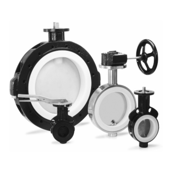
Richter Shut-off and
Control Butterfly Valve
Lug-style body:
Wafer-style body:
Keep for future use!
This operating manual must be strictly observed before
transport, installation, operation and maintenance
Subject to change without notice.
Reproduction is generally permitted with indication of the source.
© Richter Chemie-Technik GmbH
9520-072-en Revision 02 Edition 01/2012
Series NKL-C
Series NKS-C
Advertisement
Table of Contents

Related Manuals for Richter NKS-C Series


Summary of Contents for Richter NKS-C Series
- Page 1 Keep for future use! This operating manual must be strictly observed before transport, installation, operation and maintenance Subject to change without notice. Reproduction is generally permitted with indication of the source. © Richter Chemie-Technik GmbH 9520-072-en Revision 02 Edition 01/2012...
-
Page 2: Table Of Contents
Series NKS-C, NKSP-C, NKL-C, NKLP-C Page 2 List of Contents 7 Operation ..........15 List of Contents ........2 7.1 Initial commissioning ........15 Relevant documents ......... 3 7.2 Improper operation and their consequences ..............15 1 Technical data ........3 7.3 Shutdown ........... -
Page 3: Relevant Documents
For NKLP-C or NKSP-C, operating manual for ac- tuator Technical data Materials: Manufacturer: Body material: Ductile cast iron EN-JS 1049 to DIN Richter Chemie-Technik GmbH EN 1563 (0.7043 DIN 1693) Otto-Schott-Str. 2 D-47906 Kempen Lining material: PTFE .../F Telephone: +49 (0) 2152 146-0 PTFE modified .../F... -
Page 4: Overview Of Sizes
Series NKS-C, NKSP-C, NKL-C, NKLP-C Page 4 Overview of sizes /F-S /F-L-S Series Actuation /F-L /F-H /F-L-H Body design /F-T /F-L-T DN 65, 125 DN 50-200 DN 50-200 Lever 2½", 5" 2"-8" 2"-8" NKS-C DN 65, 125 DN 65, 125, Gear 2½", 5"... -
Page 5: Name Plate, Ce And Body Markings
Series NKS-C, NKSP-C, NKL-C, NKLP-C Page 5 Order example NKS-CTLL80>GSHC > Order example NKS-C Series NKSP-C Body lining Disc/stem unit Valve size Flange connection Body material Flexible inlay Actuation Type plate Name plate, CE and body markings The stainless steel name plate is undetachably riveted Sign for transport securing device for actuator to the body. -
Page 6: Tightening Torques
Series NKS-C, NKSP-C, NKL-C, NKLP-C Page 6 Pipe screws flanges ISO/DIN drilled to ASME Class Tightening torques 150 Standard threaded hole All screws greased, tighten in diametrically Flange nom. Tightening Screws opposite sequence! size torque After the plant has been started up (especially with the [mm] [inch] [ASME]... - Page 7 Series NKS-C, NKSP-C, NKL-C, NKLP-C Page 7 Pipe screws flanges ISO/DIN drilled to ASME Class Body screws 150, through hole Hex. socket head screws for lug-style and wafer-style NKS-C+NKSP-C from size DN 350 (14") upwards bodies with lug-style body and through hole Hex.
-
Page 8: Dimensions - Installation
Series NKS-C, NKSP-C, NKL-C, NKLP-C Page 8 Dimensions - Installation Nom. size Connection [mm] [inch] [mm] [mm] [mm] 2“ 2½“ 3“ 4“ 5" 6“ 8“ 10“ 12“ 14“ 16“ 18" 20" 24" 28" 30" 32" 36" 1000 40" See also Section 6.4, paragraph 1 Face to face to DIN EN 558-1, series 20 (ISO 5752, series 20) without DN 350 Connections for worm gears and brackets as per DIN ISO 5211 The inside diameter of the mounted pipe flanges must always be greater than the di-... -
Page 9: Disc/Stem Unit Stainless Steel, Hastelloy, Titan
Series NKS-C, NKSP-C, NKL-C, NKLP-C Page 9 1.6.2 Disc/stem unit stainless steel, Hastelloy, Titan Angel of opening Nom. Size 20° 20° 20° 20° [mm] [inch] 2“ 13,6 25,2 40,8 2½“ 14,0 27,4 49,4 3“ 23,2 43,9 4“ 16,9 52,4 5" 23,7 6“... -
Page 10: Breakaway Torques
Series NKS-C, NKSP-C, NKL-C, NKLP-C Page 10 Breakaway torques Cavitation coefficient z for 75% duty Nom. size [mm] [inch] [Nm] [Nm] Nom. size at kv/kvs = 75 % 2“ [mm] [inch] 2“ 0,60 2½" 2½" 0,46 3“ 3“ 0,47 4“ 4“... -
Page 11: Notes On Safety
Series NKS-C, NKSP-C, NKL-C, NKLP-C Page 11 Notes on safety This operating manual contains fundamental informa- Shut-off and control butterfly valves with a stainless tion which is to be observed during installation, opera- steel disc/stem unit are suitable for less aggressive tion and maintenance. -
Page 12: Safety Notes For Applications In Potentially Explosive Areas Based On The Directive 94/9/ Ec (Atex 95)
Series NKS-C, NKSP-C, NKL-C, NKLP-C Page 12 Safety notes for applications in potentially explosive areas based on the Directive 94/9/ EC (Atex 95) The valves are intended for use in a potentially This means that, to safely prevent ignitions, the explosive area and are therefore subject to the valve must be completely filled with medium at all conformity assessment procedure of the directive... -
Page 13: Safety Note For Valves, Certified To Clean Air Act (Ta-Luft)
Series NKS-C, NKSP-C, NKL-C, NKLP-C Page 13 Safety note for valves, certified to Clean Air Act (TA-Luft) On request, this valve can be supplied compliant with In particular, servicing must be conducted at regular the German Clean Air Code. intervals, and the bolted connections relevant for tightness must be inspected and retightened if neces- Certificate / Manufacturer Declaration Validity is de- sary. -
Page 14: Disposal
Series NKS-C, NKSP-C, NKL-C, NKLP-C Page 14 Disposal Prior to the disposal of the valve: Collect any medium, etc. which has escaped and Parts of the valve may be contaminated with medium dispose of it in accordance with the local regula- which is detrimental to health and the environment tions. -
Page 15: Operation
Series NKS-C, NKSP-C, NKL-C, NKLP-C Page 15 Operation Initial commissioning Shutdown Normally, the valves have been tested for leaks with Before loosening the flange bolts: air or water. Prior to initial operation check body bolt- ensure plant to be free of pressure ing. -
Page 16: Malfunctions
Series NKS-C, NKSP-C, NKL-C, NKLP-C Page 16 Malfunctions Flange connection ball valve/pipe is leaking Medium leaking at the partition between lower and upper halves Retighten the flange screws to a tightening torque according to Section 1.3. If this does not remedy Dismont valve and repair, probably the stem seal the leak, the recommended torques may be ex- is not tight. -
Page 17: Valve Actuation
The bracket and the coupling are thereby not re- quired. 9.2.3 Remotely actuated Richter butterfly valves can be remotely actuated by means of pneumatic, hydraulic or electric quarter-turn actuators equipped with a connection as per DIN EN ISO 5211. -
Page 18: Drawings
Series NKS-C, NKSP-C, NKL-C, NKLP-C Page 18 Drawings 10.1 Legend shell Lever unit disc/stem unit lever assembly 313/x bearing and pressure package throttling plate body lining Worm gear flexible inlay worm gear grounding rope 914/1 hex. socket screw Actuator 936/1 toothed lock washer bracket coupling... -
Page 19: Sectional Drawing Nkl-C
Series NKS-C, NKSP-C, NKL-C, NKLP-C Page 19 10.3 Sectional drawing NKL-C Lug-style body with hand lever 10.4 Worm gear 9520-072-en Revision 02 TM 8436 Edition 01/2012... -
Page 20: Actuator
Series NKS-C, NKSP-C, NKL-C, NKLP-C Page 20 10.5 Actuator 10.6 Connection actuator Connection flange to ISO 5211 2-surface 4-surface pivot pivot point point [mm] [inch] [mm] 2“ 2½" 3“ 4“ 5" 6“ 8“ 10“ 12“ 14“ 16“ 18" 20" 24" 28"... -
Page 21: Dimensional Drawing Nks-C With Hand Lever
Series NKS-C, NKSP-C, NKL-C, NKLP-C Page 21 10.7 Dimensional drawing NKS-C with hand lever øC [mm] [inch] [mm] 2“ 2½" 3“ 4“ 5" 6“ 8“ 10“ 12“ 14“ 16“ 18" Only with 20" 24" worm gear 28" 30" 32" 36" 1000 40"... -
Page 22: Dimensional Drawing Nks-C With Worm Gear
Series NKS-C, NKSP-C, NKL-C, NKLP-C Page 22 10.8 Dimensional drawing NKS-C with worm gear [mm] [inch] [mm] 2“ 28,5 45,7 43,5 67,5 2½" 28,5 45,7 43,5 67,5 3“ 28,5 45,7 43,5 67,5 4“ 28,5 45,7 43,5 67,5 5" 28,5 45,7 43,5 67,5 6“... -
Page 23: Dimensional Drawing Nksp-C
Series NKS-C, NKSP-C, NKL-C, NKLP-C Page 23 10.9 Dimensional drawing NKSP-C 9520-072-en Revision 02 TM 8436 Edition 01/2012... - Page 24 Series NKS-C, NKSP-C, NKL-C, NKLP-C Page 24 Table NKSP-C 5211 [mm] [inch] [mm] 2“ 2½" 3“ 4“ 5" 6“ 8“ 10“ 12“ 14“ 16“ 18" 20" From DN 350 (14“) 24" Lug-style body NKL-C with 28" through holes 30" 32" 36"...
-
Page 25: Dimensional Drawing Nkl-C With Hand Lever
Series NKS-C, NKSP-C, NKL-C, NKLP-C Page 25 10.10 Dimensional drawing NKL-C with hand lever øC [mm] [inch] [mm] 2“ 2½" 3“ 4“ 5" 6“ 8“ 10“ 12“ 14“ 16“ 18" Only with 20" 24" worm gear 28" 30" 32" 36" 1000 40"... -
Page 26: Dimensional Drawing Nkl-C With Worm Gear
Series NKS-C, NKSP-C, NKL-C, NKLP-C Page 26 10.11 Dimensional drawing NKL-C with worm gear [mm] [inch] [mm] 2“ 28,5 45,7 43,5 67,5 2½" 28,5 45,7 43,5 67,5 3“ 28,5 45,7 43,5 67,5 4“ 28,5 45,7 43,5 67,5 5" 28,5 45,7 43,5 67,5 6“... -
Page 27: Dimensional Drawing Nklp-C
Series NKS-C, NKSP-C, NKL-C, NKLP-C Page 27 10.12 Dimensional drawing NKLP-C 9520-072-en Revision 02 TM 8436 Edition 01/2012... - Page 28 Series NKS-C, NKSP-C, NKL-C, NKLP-C Page 28 Table NKLP-C/F 5211 [mm] [inch] [mm] 2“ 2½" 3“ 4“ 5" 6“ 8“ 10“ 12“ 14“ 16“ 18" 20" 24" 28" 30" 1040 32" 1110 36" 1232 1016 1000 40" 1345 1101 See manufacturer’s information on the dimensions for the actuator. 9520-072-en Revision 02 TM 8436...
- Page 29 ChemValve-Schmid AG Duennernstrasse 540 CH-4716 Welschenrohr www.chemvalve-schmid.com Konformitätserklärung nach EN ISO//IEC 17050 Declaration of Conformity according to EN ISO//IEC 17050 Produkt PTFE-Absperrklappe Product PTFE Lined Butterfly Valve Bauart Absperr- und Regelklappe Design Shut-off and control butterfly valve Baureihe NKL-C…, NKS-C… Serie Nennweite DN 50 bis DN 1000,...
- Page 31 Safety Information / Declaration of No Objection Concerning the Contamination of Richter-Pumps, -Valves and Components SCOPE AND PURPOSE Each entrepreneur (operator) carries the responsibility for the health and safety of his employees. This extends also to the personnel, who implements repairs with the operator or with the contractor.
- Page 32 A. Details of Richter-product: Failure description: Classification: Article number: Equipment: Serial number: Application tool: Application process: B. Condition of the Richter-product: Contamination : Was it in operation ? toxic Drained (product/operating supply item) ? caustic All openings hermetically locked! inflammable...
- Page 33 Waste Management Law (AbfG) and the Water Resources Act (WHG) An inspection/repair of Richter products and parts will only take place, if the attached explanation is filled out correctly and completely by authorized and qualified technical personnel and is available.
Need help?
Do you have a question about the NKS-C Series and is the answer not in the manual?
Questions and answers