Table of Contents
Advertisement
Quick Links
INSTALLATION AND OPERATING MANUAL
Series PA/F, PA/S
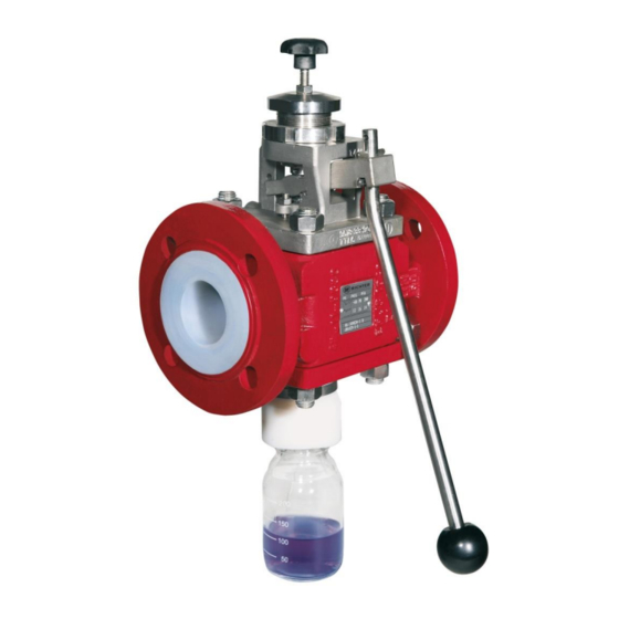
Sampling Valves
PFA-lining or
investment cast stainless steel
Keep for future use!
This operating manual must be strictly observed before
transport, installation, operation and maintenance
Subject to change without notice.
Reproduction is generally permitted with indication of the source.
© Richter Chemie-Technik GmbH
9510-060-en Revision 17 Edition 07/2016
Advertisement
Table of Contents

Subscribe to Our Youtube Channel
Related Manuals for Richter PA/F Series


Summary of Contents for Richter PA/F Series
- Page 1 Keep for future use! This operating manual must be strictly observed before transport, installation, operation and maintenance Subject to change without notice. Reproduction is generally permitted with indication of the source. © Richter Chemie-Technik GmbH 9510-060-en Revision 17 Edition 07/2016...
-
Page 2: Table Of Contents
Series PA/F, PA/S Page 2 List of Contents 7 Operation ............ 10 7.1 Initial commissioning ........ 10 List of Contents ..........2 7.2 Improper operation and their consequences . Relevant documents ......... 3 ..............10 7.3 Sampling (standard) ........11 1 Technical Data .......... -
Page 3: Relevant Documents
For PAP/F, PAP/S: Operating manual for actuator (TA-Luft) Technical Data Manufacturer: Installation position : Richter Chemie-Technik GmbH The installation position is normally horizontal with the Otto-Schott-Str. 2 bottle connection vertically downwards (deviations 47906 Kempen, Germany from this position require a special bottle connection). -
Page 4: Name Plate And Body Markings
Series PA/F, PA/S Page 4 Pipe screws, flanges ISO/DIN drilled to ASME Name plate and body mark- Class 150 ings Flange nom. Screws Tightening torque size The stainless steel name plate is undetachably riveted to the body. [mm] [inch] [ASME] [in-lbs] [Nm] If the operator attaches his identification, it must be... -
Page 5: Viscosity-Pressure Diagram
For valves which are used in potentially explosive areas, see Section 3. Intended use Installation, operation and maintenance are to be Richter sampling valves are pressure-maintaining performed by qualified staff. components accordance with Pressure The area of responsibility, authority and supervision of Equipment Directive (DGRL) for taking liquid samples. -
Page 6: For The Customer / Operator
Series PA/F, PA/S Page 6 For the customer / operator Improper operation If a valve is used, the operator must ensure that The operational reliability of the valve supplied is only actuators which are retrofitted are adapted to suit guaranteed if it is used properly in accordance with Section 2.1 of this operating manual. -
Page 7: Safety Note For Valves, Certified To German Clean Air Act (Ta Luft)
Series PA/F, PA/S Page 7 Increased wear to the valve can be expected with This means that, to safely prevent ignitions, the valve must be completely filled with medium at all the conveyance of liquids containing abrasive times or else a potentially explosive atmosphere constituents. -
Page 8: Transport, Storage And Disposal
Series PA/F, PA/S Page 8 Transport, storage and disposal It is imperative, for all transport work, to Return consignments observe generally accepted engineering practice accident prevention Valves which have conveyed aggressive or regulations. toxic media must be well rinsed and cleaned The valve is supplied with flange caps. -
Page 9: Installation
These the setting instructions in Section 6.7. gaskets are available as special accessories in the Richter range. Setting instructions Direction of flow and Press the sampling lever in the direction of the valve. -
Page 10: Needle Adapter For Pa/S Dn25
Series PA/F, PA/S Page 10 Needle adapter for PA/S DN25 When you use a stainless steel needle adapter for PA/S DN25 make sure that you insert the flat gasket. Operation 7.1 Initial commissioning Improper operation and their consequences Normally, the ball valves have been tested ... -
Page 11: Sampling (Standard)
Series PA/F, PA/S Page 11 A lock is available from Richter as an option. Sampling (standard) A device, screw fitting 917 for example, for the risk- free discharge of the medium must be connected to the venting connection. Sealing plugs are not allowed because this results in overpressure in the bottle. -
Page 12: Maintenance
Series PA/F, PA/S Page 12 Maintenance All repair work is to be performed by qualified Undo spring bush 514. personnel using the appropriate tools. Generally recognised practice in mechanical engineering is to be observed. For the arrangement, designation and item numbers of all parts of the valve, see Section 10. -
Page 13: Disassembling Pa/S And Removing The Packing Rings
Series PA/F, PA/S Page 13 Undo both hex nuts 920 of packing gland follower Disassembling PA/S and 503. removing the packing rings Unscrew cap nut 927, remove disc 550 and bottle connection 226. Loosen groove nut 509. Star knob 963 can remain screwed in. -
Page 14: Assembling Pa/F And Inserting The Packing Rings
Series PA/F, PA/S Page 14 Undo hex nuts 920 of cover 106. Remove stud screws 902. Remove packing gland follower 503. Remove thrust ring 405 from cover 106. Remove cover 106 and the stud screws 902. ... - Page 15 Series PA/F, PA/S Page 15 Insert guide ring 302 from the bottom into cover Insert actuation 515 into cover 106. 106, and push the ring into the groove. Insert stem 855 and bellows 206 into cover 106. ...
-
Page 16: Assembling Pa/S And Inserting The Packing Rings
Series PA/F, PA/S Page 16 Move actuation 515 into dead man´s position. Tighten both stud screws 920 of packing gland follower 503. Screw on spring bush 514. Note: Use your right hand to push actuation 515 Tighten setscrew 904 in spring bush 514. up, and at the same time use your left hand to tighten spring bush 514 until the stop. - Page 17 Series PA/F, PA/S Page 17 Turn cover 106 around, and insert two packing Insert stem 855 and bellows 206 into cover 106. rings 402. ATTENTION: Offset overlapping from ring to ring by 60° to 90°. Place cover 106 on body 100. Make sure that actuation 515 is located on the same side as the name plate.
- Page 18 Series PA/F, PA/S Page 18 Tighten both stud screws 920 of packing gland follower 503. Insert spring pressure 952. Tighten setscrew 904 in spring bush 514. Mount spring bonnet 513 with groove nut 509. Note: The thread of spring bonnet 513 must be just visible at the bottom.
-
Page 19: Sectional Drawings And Options
Series PA/F, PA/S Page 19 Sectional drawings and options 10.1 Legend PA/F body spring bush transistion flange (DN 40, 80) actuation cover washer (DN 25, DN 40) lever grooved pin seat coupling bellows actuator bottle connection stem 302/x guide ring 902/x stud screw O-ring... -
Page 20: Sectional Drawing Pa/F Horizontal Installation
Series PA/F, PA/S Page 20 10.3 Sectional drawing PA/F horizontal installation * view displaced by 90° ** view displaced by 45° 9510-060-en Revision 17 TM 9549 Edition 07/2016... -
Page 21: Details
Series PA/F, PA/S Page 21 10.4 Details PA/F DN 25 PA/F DN 40, 80 * view displaced ** not DN 80 9510-060-en Revision 17 TM 9549 Edition 07/2016... -
Page 22: Pa/F Vertical Installation
Series PA/F, PA/S Page 22 10.5 PA/F vertical installation 10.6 PA/F, PAP/F Option high-viscosity media 9510-060-en Revision 17 TM 9549 Edition 07/2016... -
Page 23: Sectional Drawing Pa/S
Series PA/F, PA/S Page 23 10.7 Sectional drawing PA/S view displaced by 90° ** view displaced by 45° 9510-060-en Revision 17 TM 9549 Edition 07/2016... -
Page 24: Detail Pa/S Dn 25
Series PA/F, PA/S Page 24 10.8 Detail PA/S DN 25 10.9 PA/S, PAP/S Option high-viscosity media 9510-060-en Revision 17 TM 9549 Edition 07/2016... -
Page 25: Pa/S Vertical Installation
Series PA/F, PA/S Page 25 10.10 PA/S Vertical installation 10.11 PAP/F, PAP/S 9510-060-en Revision 17 TM 9549 Edition 07/2016... -
Page 26: Dimensional Drawing Pa/F
Series PA/F, PA/S Page 26 10.12 Dimensional drawing PA/F H max. EN 558 Series 1 inch inch inch inch inch inch 4.84 7.48 ca.200 ca.7.87 ca.235 ca.9.25 1½ 9.84 ca.200 ca.7.87 ca.175 ca.6.89 7.87 5.16 7.68 ca.200 ca.7.87 ca.230 ca.9.06 9.06 6.81 12.2... -
Page 27: Dimensional Drawing Pa/F Vertical Intallation
Series PA/F, PA/S Page 27 10.13 Dimensional drawing PA/F vertical intallation H max. EN 558 Series inch inch inch inch inch inch 5.98 7.48 ca.235 ca.9.25 1½ 6.14 9.84 ca.200 ca.7.87 ca.175 ca.6.89 7.87 6.29 7.68 ca.230 ca.9.06 9.06 7.95 12.2 ca. -
Page 28: Dimensional Drawing Pa/F With Handwheel
Series PA/F, PA/S Page 28 10.14 Dimensional drawing PA/F with handwheel H max. EN 558 Series inch inch inch inch 4.84 7.36 1½ 9510-060-en Revision 17 TM 9549 Edition 07/2016... -
Page 29: Dimensional Drawing Pa/S Horizontal Installation
Series PA/F, PA/S Page 29 10.15 Dimensional drawing PA/S horizontal installation H max. EN 558 Series inch inch inch inch inch inch 4.17 7.48 ca.220 ca.8.66 ca.185 ca.7.28 4.80 7.68 ca.212 ca.8.34 9.06 9510-060-en Revision 17 TM 9549 Edition 07/2016... -
Page 30: Dimensional Drawing Pa/S Vertical Installation
Series PA/F, PA/S Page 30 10.16 Dimensional drawing PA/S vertical installation H max. EN 558 Series inch inch inch inch inch inch 168,5 6.63 7.48 ca.203 ca.8.00 ca.181 ca.7.12 178,5 7.02 7.68 ca.230 ca.9.06 9.06 9510-060-en Revision 17 TM 9549 Edition 07/2016... -
Page 31: Dimensional Drawing Pa/S With Handwheel
Series PA/F, PA/S Page 31 10.17 Dimensional drawing PA/S with handwheel H max. EN 558 Series inch inch inch inch 4.17 7.36 9510-060-en Revision 17 TM 9549 Edition 07/2016... -
Page 32: Flange Connection
Series PA/F, PA/S Page 32 10.18 Flange connection EN 558 Reihe 1 ASME B16.5 Class 150 ØD Øk n x d1 Øk n x d1 inch inch inch 4 x ⅝“ 4x14 79,5 3.12 4x16 4 x ⅝“ 1½ 4x18 98,5 3.87 4x16... - Page 35 A Unit of IDX Corporation Herstellererklärung / Manufacturer´s Declaration TA-Luft / German Clean Air Act (TA-Luft) Richter Probenahme-Ventil / Richter Sampling Valve Hiermit erklären wir, dass die Probenahme-Ventile der Baureihen Hereby we declare, that the Sampling Valves of the series PA/F, PA/S die Anforderung bezüglich der Gleichwertigkeit gemäß...
- Page 36 Safety Information / Declaration of No Objection Concerning the Contamination of Richter-Pumps, -Valves and Components SCOPE AND PURPOSE Each entrepreneur (operator) carries the responsibility for the health and safety of his employees. This extends also to the personnel, who implements repairs with the operator or with the contractor.
- Page 37 Fax : End user : A. Details of Richter-product: Failure description: Classification: Article number: Serial number: B. Condition of the Richter-product: Contamination : Was it in operation ? toxic Drained (product/operating supply item) ? caustic All openings hermetically locked! inflammable...
- Page 38 Waste Management Law (AbfG) and the Water Resources Act (WHG) An inspection/repair of Richter products and parts will only take place, if the attached explanation is filled out correctly and completely by authorized and qualified technical personnel and is available.
Need help?
Do you have a question about the PA/F Series and is the answer not in the manual?
Questions and answers