Advertisement
Quick Links
INSTALLATION MANUAL
Level of Difficulty
Moderate
Weight Capacity
Gross trailer weight (GTW)
Vertical load
Parts List
Item Qty Description
1
1
Base weldment
2
1
Upper weldment
3
1
Lower coupler assembly
4
1
Lube plate
5
2
Hex head cap screw, 1/2"
6
2
Nylock nut, 1/2"
7
1
Bushing
8
1
Hex bolt, M20
9
1
Nylock nut, M20
10
1
Flat washer, M20
11
4
Spacer, 0.094"
12
4
Base rail mounting clip
13
4
Base rail mounting pin, 1/2"
Tools Required
Ratchet
Torque wrench
Socket set
--
Torque Specifications
1/2" bolt
65 ft-lbs.
M20 bolt
300 ft-lbs.
Use above torque setting unless otherwise noted
Product Registration
CURT stands behind our products with
industry-leading warranties. Provide
feedback and help us to improve our
products by registering your purchase at:
warranty.curtgroup.com/surveys
NOTICE
Before you begin installation,
read all instructions thoroughly.
Proper tools will improve the quality of
installation and reduce the time required.
To help prevent damage to the product
or vehicle, refer to the specified torque
specifications when securing hardware
during the installation process.
CURTMFG.COM
•
PRODUCT SUPPORT: 877.287.8634
DANGER ZONE PRECAUTIONS
Block all trailer tires in front and behind with appropriate wheel chocks. Do not
substitute objects such as, but not limited to: stones, wood blocks, etc. Front
trailer lifting jacks must be supporting the trailer and resting on a firm and level surface.
Towing vehicle must be stationary with automatic transmission
20,000 lbs.
in park (manual in neutral), emergency brake applied and engine off.
5,000 lbs.
WARNING
Fully instruct and demonstrate the operation of this 5th wheel hitch to the end user. Include the
importance of observing all warnings contained herein, including warning labels on 5th wheel
hitch main body. Provide this manual in its entirety to the end user. Serious injury or death may
result if the warnings above are not observed.
Do not expose hands, body parts or clothing between the truck and
trailer or the truck's bed sides and trailer. If you must place any part
of your body under trailer or between truck and trailer, you must:
1. Block all trailer tires with wheel chocks.
2. Make sure trailer landing gear / jacks are resting on a firm, level surface.
3. Towing vehicle must be stationary with auto transmission in park
(manual in neutral), emergency brake applied and engine off.
Never exceed the towing capacity (trailer and contents combined)
of any towing system component or your vehicle.
Improperly coupled trailers can separate or drop without notice,
causing serious injury or death. To reduce the chance of serious injury or death:
Never attempt to couple trailer without reading and following all instructions thoroughly.
Always follow operating instructions to secure trailer to tow vehicle.
Make sure the hitch is secure before towing.
Prior to towing, ensure all components and hardware are structurally sound and secure.
Always chock the trailer to prevent movement while coupling the hitch.
Always ensure lynch pins are installed through handle before towing.
Always perform a pull test prior to towing. See 'pull test' later in this instruction manual.
Never position anyone under the trailer's kingpin area during coupling and uncoupling.
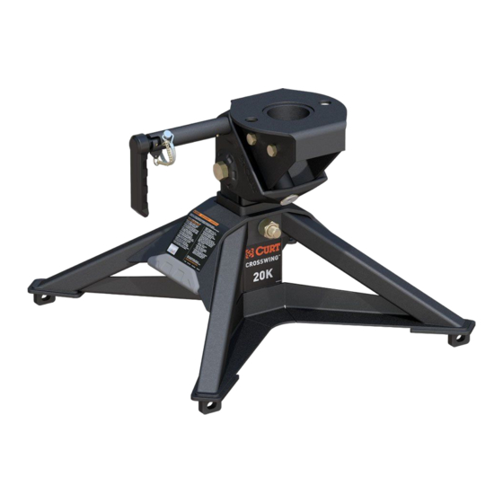
Product Photo
•
16600-INS-RA
•
12/08/2021
•
ECN9081
•
PAGE 1
16600
Advertisement

Subscribe to Our Youtube Channel
Related Manuals for Curt Manufacturing 16600


Summary of Contents for Curt Manufacturing 16600
- Page 1 INSTALLATION MANUAL 16600 Level of Difficulty DANGER ZONE PRECAUTIONS Moderate Block all trailer tires in front and behind with appropriate wheel chocks. Do not substitute objects such as, but not limited to: stones, wood blocks, etc. Front trailer lifting jacks must be supporting the trailer and resting on a firm and level surface.
- Page 2 5th wheel, assemble the lower coupler assembly to the base weldment using the appropriate holes. Occasionally, the trailer's kingpin pin box will require adjustment to facilitate correct ride height. CURTMFG.COM • PRODUCT SUPPORT: 877.287.8634 • 16600-INS-RA • 12/08/2021 • ECN9081 • PAGE 2...
- Page 3 Each base rail must have a bolt Rear edge of truck bed in either of the marked holes. Check to rear edge of base rail for obstructions before drilling CURTMFG.COM • PRODUCT SUPPORT: 877.287.8634 • 16600-INS-RA • 12/08/2021 • ECN9081 • PAGE 3...
- Page 4 1/2" hex bolts (#5) through the upper weldment and secure with 1/2" nylock nuts (#6). Step 3 Make sure the the upper weldment (#2) spins freely around the king pin. CURTMFG.COM • PRODUCT SUPPORT: 877.287.8634 • 16600-INS-RA • 12/08/2021 • ECN9081 • PAGE 4...
- Page 5 Check to make sure 20mm bolt holding the lower coupler assembly to the base is not loose if needed re-torque to 300 ft-lbs. CURTMFG.COM • PRODUCT SUPPORT: 877.287.8634 • 16600-INS-RA • 12/08/2021 • ECN9081 • PAGE 5...
- Page 6 Remove the parking brake and slowly drive the tow vehicle out from under the trailer. If resistance is encountered, determine the corrective action and repeat uncoupling steps. CURTMFG.COM • PRODUCT SUPPORT: 877.287.8634 • 16600-INS-RA • 12/08/2021 • ECN9081 • PAGE 6...
- Page 7 1. Remove the base rail pins & clips. 2. Remove the 5th wheel unit from the base rails. Re-installation Reinstall the 5th wheel in the reverse order it was removed. CURTMFG.COM • PRODUCT SUPPORT: 877.287.8634 • 16600-INS-RA • 12/08/2021 • ECN9081 • PAGE 7...
-
Page 8: Maintenance
If hitch head appears loose the 20mm bolt can be removed and inspected for damage if any cracks or damage is visible immediately discontinue use of hitch. CURTMFG.COM • PRODUCT SUPPORT: 877.287.8634 • 16600-INS-RA • 12/08/2021 • ECN9081 •...
Need help?
Do you have a question about the 16600 and is the answer not in the manual?
Questions and answers