Table of Contents
Advertisement
Quick Links
AZ Series/Motorized Actuator equipped
with AZ Series
mini Driver
EtherCAT Drive Profile Compatible
USER MANUAL
Thank you for purchasing an Oriental Motor product.
This Manual describes product handling procedures and safety precautions.
• Please read it thoroughly to ensure safe operation.
• Always keep the manual where it is readily available.
HM-60457
Introduction
Hardware
EtherCAT
communication
Object list
Troubleshooting
Reference materials
Advertisement
Table of Contents

Subscribe to Our Youtube Channel
Related Manuals for Oriental motor aSTEP AZ Series


Summary of Contents for Oriental motor aSTEP AZ Series
- Page 1 USER MANUAL Troubleshooting Reference materials Thank you for purchasing an Oriental Motor product. This Manual describes product handling procedures and safety precautions. • Please read it thoroughly to ensure safe operation. • Always keep the manual where it is readily available.
-
Page 2: Table Of Contents
Introduction Before using the product ............................6 Operating manuals ..............................7 Related operating manuals ..................................7 How to use operating manuals................................7 Overview of the product ............................. 9 Safety precautions ..............................10 Precautions for use ..............................12 Hardware System configuration ..............................16 Preparation ..................................17 Checking the product ..................................17 How to identify the product model ............................... - Page 3 EtherCAT communication Guidance ..................................36 Communications specifications ..........................39 EtherCAT communication interface ............................... 39 CiA402 drive profile....................................39 EtherCAT state machine (ESM) ................................. 40 Process data object (PDO) ................................. 40 Service data object (SDO) .................................. 43 Synchronous mode of EtherCAT communication........................43 Distributed Clocks ....................................
- Page 4 Object list Timing for parameter to update ..........................130 Objects of CoE communication area ........................131 Objects of profile area .............................133 Objects of manufacturer-specific area .........................135 Troubleshooting Alarms ..................................148 Alarm reset ......................................148 Alarm history ......................................148 Generation condition of alarms ..............................148 Alarms list ......................................149 Timing chart......................................155 Information ................................156 Information history ....................................158...
- Page 5 Introduction This part explains the product overview and safety precautions in addition to the types and descriptions about operating manuals. Table of contents Before using the product ....... 6 Operating manuals ......... 7 2-1 Related operating manuals ......7 2-2 How to use operating manuals ....7 Overview of the product ......
-
Page 6: Before Using The Product
The product described in this document has been designed and manufactured to be incorporated in general industrial equipment. Do not use for any other purpose. Oriental Motor Co., Ltd. is not responsible for any compensation for damage caused through failure to observe this warning. -
Page 7: Operating Manuals
Operating manuals Operating manuals Related operating manuals For operating manuals, download from Oriental Motor Website Download Page or contact your nearest Oriental Motor sales office. • AZ Series/Motorized Actuator equipped with AZ Series mini Driver EtherCAT Drive Profile Compatible USER MANUAL (this document) •... - Page 8 Operating manuals Installation and connection Before starting operation Setting of node address 2 Hardware 1 Before starting operation *1 2 Hardware Setting of parameters Operation 3 EtherCAT communication EtherCAT communication 4 Object lists I/O signals 4 Parameters Measures for various cases 7 Address/code lists 11 Appendix *2 *1 When a motorized actuator is used, the following contents cannot be operated via EtherCAT communication.
-
Page 9: Overview Of The Product
XML format. By importing the ESI file to the EtherCAT Configuration Tool of a PLC (programmable controller), the settings of EtherCAT communication can be configured before the driver is delivered. For details, contact your nearest Oriental Motor sales office. -
Page 10: Safety Precautions
Safety precautions Safety precautions The precautions described below are intended to ensure the safe and correct use of the product, and to prevent the customer and others from exposure to the risk of injury. Use the product only after carefully reading and fully understanding these instructions. - Page 11 Safety precautions General • Do not use the driver beyond the specifications. Doing so may result in electric shock, injury, or damage to equipment. • Keep your fingers and objects out of the openings in the driver. Failure to do so may result in fire, electrical shock, or injury.
-
Page 12: Precautions For Use
Precautions for use This chapter explains restrictions and requirements the user should consider when using the product. z Always use Oriental Motor cables to connect a motor and a driver. Refer to the cable models on p.32. z When conducting the insulation resistance measurement or the dielectric strength test, be sure to separate the connection between the motor and the driver. - Page 13 Precautions for use z How to fix the cable Fix the cable at two places near the connectors as shown in the figure or fix it with a wide clamp to take measures to prevent stress from being applied to the connectors. In the case of a exible cable, this area is a movable range.
- Page 15 Hardware This part explains names and functions of each part of the driver, installation and connection methods, and so Table of contents System configuration ......16 4-3 Connecting the EtherCAT cable (CN3/CN4) ............25 Preparation ..........17 4-4 Connecting the USB cable ......25 2-1 Checking the product ........
-
Page 16: System Configuration
System configuration System configuration PC in which the MEXE02 Host controller has been installed EtherCAT communication Driver EtherCAT communication compatible product Control power AC power Circuit supply *1 Noise lter supply breaker *2 Main power AC power Circuit supply Noise lter supply breaker *2 Motor... -
Page 17: Preparation
Preparation Preparation This chapter explains the items you should check, as well as names and functions of each part. Checking the product Verify that the items listed below are included. Report any missing or damaged items to the branch or sales office from which you purchased the product. -
Page 18: Information About Nameplate
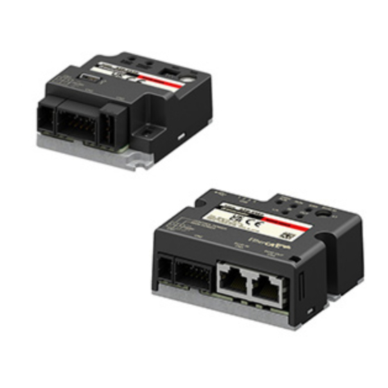
Preparation Information about nameplate The figure shows an example. Driver model Serial number Manufacturing date Names and functions of parts PWR/ALM LED (Green/Red/Blue) RUN LED (Green) Input signal connector (CN5) ERR LED (Red) USB connector Node address setting switch (ECAT ID ×1) L/A LED (Green) Mounting hole Cutout for mounting... -
Page 19: Indication Of Leds
Preparation Type Name Sign Description EtherCAT communication Connects with the EtherCAT communication ECAT OUT connector (CN4) compatible product of the following node address. Connector Input signal connector (CN5) − Connects when using direct I/O or sensors. Indication of LEDs „ LED indication related to driver status PWR/ALM LED status Description No light... -
Page 20: Installation
Installation Installation This chapter explains the installation location and installation method of the driver. Installation location The driver is designed and manufactured to be incorporated in equipment. Install it in a well-ventilated location that provides easy access for inspection. The location must also satisfy the following conditions: •... - Page 21 Installation „ Dimensions [Unit: mm (in.)] Mass: 0.11 kg (0.24 lb.) 69 [2.72] 4 [0.16] 61 [2.4] 30 [1.18] 2 [0.08]...
-
Page 22: Connection
Circuit breaker *3 Motor Connect to CN1 *1 It is an Oriental motor cable. Purchase is required separately. *2 Connecting the control power supply allows you to continue monitoring even if the main power supply is shut off. Connect it as necessary. -
Page 23: Connecting The Main Power Supply And The Control Power Supply (Cn1)
Connection Connecting the main power supply and the control power supply (CN1) Connect a main power supply to the CN1 connector. Connecting the control power supply allows you to continue monitoring even if the main power supply is shut off. Connect it as necessary. - Page 24 Connection „ Internal input circuit The driver can be used with the main power supply and control power supply, or with the main power supply only. When using only the main power supply, the power is supplied from the main power supply to the control power supply circuit inside the driver.
-
Page 25: Connecting The Ethercat Cable (Cn3/Cn4)
Connection Connecting the EtherCAT cable (CN3/CN4) Connect an EtherCAT master to the CN3 (ECAT IN) connector on the driver using the EtherCAT cable. Be sure to connect from the CN4 (ECAT OUT) connector to the CN3 (ECAT IN) connector when connecting between drivers. -
Page 26: Connecting Input Signals (Cn5)
Connection Connecting input signals (CN5) Connect when using direct I/O or sensors. „ Applicable lead wire and terminal • AWG26 to 20 (0.14 to 0.5 mm Applicable lead wire • Lead wire strip length: 6 mm (0.24 in.) Without sleeve: 0.25 to 0.5 mm Applicable ferrule terminal With sleeve: 0.25 to 0.34 mm „... -
Page 27: Noise Elimination Measures
• When relays or electromagnetic switches are used, use noise filters or CR circuits to suppress surge generated by them. • Use an Oriental Motor connection cable when extending the wiring distance between a motor and a driver. Refer to p.32 for the model name. This is effective in suppressing the electrical noise emitted from the motor. - Page 28 Connection z Connecting the motor cable Use an Oriental Motor connection cable when extending the wiring distance between a motor and a driver. Refer to p.32 for the model name. z Connecting the signal cable Refer to “Prevention of noise propagation” on p.27.
- Page 29 Connection • The driver uses components that are sensitive to static electricity. Take measures against static electricity since static electricity may cause the driver to malfunction or suffer damage. • When connecting the following products, cover the motor cable with a shielded braided sleeving. Use the cable clamps to ground both ends of the shielded braided sleeving.
-
Page 30: Setting Of Node Address
Setting of node address Setting of node address This chapter explains how to set the node address. Setting method Use the node address setting switch (ECAT ID ×1) to set the node address. The node address setting switch is hexadecimal. Convert the node address from decimal to hexadecimal to set. When connecting two or more EtherCAT communication compatible products, do not set duplicate node addresses. -
Page 31: Inspection And Maintenance
Inspection It is recommended that periodic inspections are conducted for the items listed below after each operation of the motor. If an abnormality is found, discontinue any use and contact your nearest Oriental Motor sales office. „ Inspection item • Check if the openings in the driver are clogged. -
Page 32: Cable
Cable Cable Connection cables „ Connection cables/Flexible connection cables (For AZM14, AZM15, AZM24, AZM26) These cables are used when connecting a motor and a driver. Connection cable When installing the motor on a moving part, use a flexible cable. z Connection cables z Flexible connection cables For motor/encoder For motor/encoder... - Page 33 Cable „ Connection cables/Flexible connection cables (For AZM46, AZM48, AZM66, AZM69) These cables are used when connecting a motor and a driver. The figure shows an example when the electromagnetic brake motor is used. Connection cable When installing the motor on a moving part, use a flexible cable. z Connection cables For motor/encoder For motor/encoder/electromagnetic brake...
- Page 34 Cable „ Extension cables/Flexible extension cables These cables are used when extending a connection cable (add between the driver and connection cable). Use if the length of the connection cable used is not enough when extending the distance between a motor and a driver.
- Page 35 EtherCAT communication This part explains how to control via EtherCAT communication. Table of contents Guidance ..........36 Functions ..........80 4-1 Touch probe ............80 Communications specifications ..39 4-2 Resolution ............83 2-1 EtherCAT communication interface ..39 4-3 Wrap function ..........
-
Page 36: Guidance
Guidance Guidance If you are new to this product, read this chapter to understand the operating methods along with the operation flow. This is an example how to operate the motor via EtherCAT communication. STEP 1 Installation and connection STEP 2 Before starting operation ... - Page 37 Circuit breaker *3 Motor Connect to CN1 *1 It is an Oriental motor cable. Purchase is required separately. *2 Connecting the control power supply allows you to continue monitoring even if the main power supply is shut off. Connect it as necessary.
- Page 38 Guidance STEP 5 Were you able to operate? How did it go? Were you able to operate the motor properly? If the motor does not operate, check the following points. • Is the PWR/ALM LED blinking in red? An alarm is being generated. Refer to p.148 for details. •...
-
Page 39: Communications Specifications
Communications specifications Communications specifications EtherCAT communication interface Item Description Communications standards IEC 61158 Type12 Physical layer/Protocol 100 BASE-TX (IEEE 802.3) Transmission rate 100 Mbps • Free Run mode: 1 ms or more Communication cycle • Sync manager 2 event synchronization mode: 1 ms or more •... -
Page 40: Ethercat State Machine (Esm)
Communications specifications EtherCAT state machine (ESM) The EtherCAT state machine (ESM) is controlled by the EtherCAT master. Init Pre-Operational Safe-Operational Operational Transmit PDO Receive PDO ESM State Status communication (TxPDO) (RxPDO) During initialization. Communication Init Not possible Not possible Not possible cannot be performed. - Page 41 Communications specifications „ PDO mapping object Up to 16 objects can be mapped in a single PDO. Receive PDO mapping object Transmit PDO mapping object Receive PDO Index Transmit PDO Index RxPDO1 1600h TxPDO1 1A00h RxPDO2 1601h TxPDO2 1A01h Objects to be mapped in PDO are as follows. Objects of profile area Objects of manufacturer-specific area 6000h to 67FFh...
- Page 42 Communications specifications „ Example of PDO mapping This section introduces an example of PDO mapping. Data of 2 bytes and 4 bytes are little-endian. With the Sync manager 2 and Sync manager 3 PDO assignment objects, set the mapping of PDO communication by selecting the PDO mapping object that performs communication actually.
-
Page 43: Service Data Object (Sdo)
Communications specifications Service data object (SDO) When read and write of the parameter object is performed, or monitor is executed via EtherCAT communication, the Service data object (SDO) is used. SDO is not synchronized to EtherCAT communication cycles, but it is sent and received in an arbitrary timing. -
Page 44: Distributed Clocks
Communications specifications Distributed Clocks The Distributed Clocks (DC) is a method to synchronize operation by sharing the same clock between the EtherCAT master and the driver. The interruption signal (SYNC0) is output at a precise interval based on the DC. In the DC mode, an application is executed in synchronization with SYNC0. -
Page 45: Drive Profile
Drive profile Drive profile Drive state machine The drive state machine is controlled by the Controlword object (6040h). The status of each state can be checked with the Statusword object (6041h). Control Main Start power power Motor supply supply (A): Lower-level power Not ready to (B): High-level power switch on... - Page 46 Drive profile „ State transition of drive state machine The drive state machine is controlled by the Controlword object (6040h). z Controlword object (6040h) Bit 15 Bit 14 Bit 13 Bit 12 Bit 11 Bit 10 Bit 9 Bit 8 Manufacturer specific (ms) Reserved Halt...
- Page 47 Drive profile State Motor operation Event Action An alarm of Network bus error is generated (alarm code 81h). After transitioning from The ESM transitions to other than "Fault reaction active" to "Fault," the motor Operational. puts into a non-excitation state. (Transition number 13, 14) An alarm of Main power supply off is Operation...
-
Page 48: Operation Modes
Drive profile Operation modes The driver supports the operation modes listed below. • Cyclic synchronous position mode (CSP) • Profile position mode (PP) • Cyclic synchronous velocity mode (CSV) • Profile velocity mode (PV) • Homing mode (HM) „ Switching of operation mode The operation mode can be switched by the Modes of operation (6060h). - Page 49 Drive profile Index Name Type Access Save Range Update Position actual value 6064h INT32 TxPDO − − − [step] −2,147,483,648 to 607Ah Target position [step] INT32 RxPDO − 2,147,483,647 (Initial value: 0) −2,147,483,648 to Min. position limit [step] INT32 2,147,483,647 (Initial value: ...
-
Page 50: Profile Position Mode (Pp)
Drive profile Name Value Description The target position command is disabled. When the state is any of the followings, the value changes to 0 and the target position is disabled. • The drive state machine is other than "Operation enabled." Target position •... - Page 51 Drive profile Index Name Type Access Save Range Update Profile deceleration 1 to 1,000,000,000 (Initial 6084h RxPDO [step/s value: 300,000) 0 to 4,000,000 (Initial value: 4142h Starting speed [Hz] INT32 5,000) 0: Wrap absolute positioning 1: Wrap proximity 414Fh Wrap positioning mode RxPDO...
- Page 52 Drive profile Name Value Description When the New set point (6040h: Bit 4) is set from 0 to 1 during operation, the new operation command is stored. When the present operation is completed, the stored new operation command is started. Change set When the New set point (6040h: Bit 4) is set from 0 to 1 during operation, the new immediately...
- Page 53 Drive profile Name Value Description The function limitation by the internal limit is not in an active state. The function limitation by the internal limit became an active state. The value changes to 1 when any of the following internal limit functions are activated.
- Page 54 Drive profile Single set-point [When the Change set immediately (6040h: Bit 5) is 1] If the New set point (6040h: Bit 4) is newly set during operation, the new operation command is applied immediately. Velocity Reference speed Target position (607Ah) New set point (6040h: Bit 4) Set point acknowledge...
- Page 55 Drive profile When a mechanism installed to the motor had presses against a load When a load is pressed, the TLC (6041h: Bit 15) of Statusword changes to 1. If the "Halt (6040h: Bit 8)" of Controlword is set to 1 or the STOP input is turned ON, the operation is stopped and the push-motion status is canceled.
- Page 56 Drive profile z Wrap absolute positioning operation After the Target position (607Ah) is set and the Wrap (6040h: Bit 14) is set to 1, wrap absolute positioning operation is started when the New set point (6040h: Bit 4) is set to 1. With wrap absolute positioning operation, absolute positioning operation is performed regardless of the value of the Abs/Rel (6040h: Bit 6).
- Page 57 Drive profile z Absolute positioning Positioning operation is performed from the present position to the set target position. In the Target position (607Ah), set the target position on the coordinates with the home as a reference. Example: When moving from the command position "1,000" to the target position "4,000" Set 4,000 steps in the Target position (607Ah) to start absolute positioning operation.
- Page 58 Drive profile z Wrap absolute positioning Positioning operation is performed to the target position within the wrap range. In the Target position (607Ah), set the target position within the wrap range. Refer to p.84 for the wrap function. Example: When moving from the command position "1,000" to the target position "4,000” (wrap setting range 1.0 rev, wrap offset ratio 50.00 %) Set the items in the table to start wrap absolute positioning operation.
- Page 59 Drive profile z Wrap forward direction absolute positioning Positioning operation in the forward direction is performed to the target position within the wrap range. In the Target position (607Ah), set the target position within the wrap range. Refer to p.84 for the wrap function. Example: When moving from the command position "1,000"...
- Page 60 Drive profile „ Orbit comparison of positioning operation These are examples when the wrap setting range is set to 1 rev and the wrap range offset ratio is set to 50 %. Initial value Æ The value set in the "Target position (607Ah)" Operation mode 2,500 Æ...
-
Page 61: Cyclic Synchronous Velocity Mode (Csv)
Drive profile Cyclic synchronous velocity mode (CSV) In the Cyclic synchronous velocity mode, a path generation (profile generation) is performed by the EtherCAT master. By cyclic synchronous communication, when the Target velocity (60FFh) is sent from the EtherCAT master to the driver, the driver performs speed controls. - Page 62 Drive profile Bit 13 Bit 12 Operation mode Description Performs continuous operation at the Target velocity (60FFh). Continuous operation When a mechanism installed to the motor presses against a load, (push-motion) * pressure is continuously applied to the load. In the Cyclic synchronous velocity mode, the movement is the Continuous operation same between continuous operation (push-motion) and (torque control) *...
-
Page 63: Profile Velocity Mode (Pv)
Drive profile Name Value Description Information is not generated. When the cause of information is cleared, the Warning is automatically Warning cleared to 0. Information is being generated. For Bit 6 to Bit 0, refer to “Status output of drive state machine” on p.47. „... - Page 64 Drive profile Details of Controlword Name Value Description − Selects the operation mode of the Profile velocity mode. The operation mode Type changed is updated immediately. For details, refer to “Operation mode of Profile − velocity mode”. Operation is allowed. Halt Stops the operation.
- Page 65 Drive profile „ Statusword of Profile velocity mode Bit 15 Bit 14 Bit 13 Bit 12 Bit 11 Bit 10 Bit 9 Bit 8 Manufacturer specific Operation mode specific Internal Target Remote limit active reached − − Speed − Bit 7 Bit 6 Bit 5 Bit 4...
-
Page 66: Homing Mode (Hm)
Drive profile „ Operation in Profile velocity mode Reference speed Trigger input Pro le deceleration (6083h) (6084h) Starting speed (4142h) Target speed (60FFh) Halt (6040h: Bit 8) Speed (6041h: Bit 12) Target reached (6041h: Bit 10) V1, V2: velocity When the Type (6040h: Bit 13, Bit 12) is set to continuous operation (torque control), self-start operation (rectangular operation) at the Target velocity (60FFh) is performed. - Page 67 Drive profile Details of Controlword Name Value Description Operation is allowed. Halt Stops the operation. The stopping method is in accordance with the setting of the Halt option code (605Dh). Start of return-to-home operation If the "Homing operation start" is set to 0 during return-to-home operation, the motor decelerates to a stop.
- Page 68 Return-to-home by the home sensor (HOMES). Starts in the positive direction. Return-to-home by the home sensor (HOMES). Starts in the negative direction. 35, 37 * Home preset −1 Return-to-home of Oriental Motor’s specifications * 35 and 37 perform the same action. z Related objects Index Name...
- Page 69 Drive profile z Return-to-home operation of Oriental Motor’s specifications When the Homing method (6098h) is set to −1, the return-to-home mode of Oriental Motor’s specifications is applied. Related objects (Oriental Motor’s specifications) Index Name Type Access Save Range Update −2,147,483,648 to...
- Page 70 (HOMES) Positive limit switch (FW-LS) In the case of return-to-home operation of Oriental Motor’s specifications, the same operation is performed if the following data is set. • (HOME) Home-seeking mode (4160h): 1 [3-sensor] • (HOME) Starting direction (4161h): 1 [positive side] •...
- Page 71 Drive profile In the case of return-to-home operation of Oriental Motor’s specifications, the same operation is performed if the following data is set. • (HOME) Home-seeking mode (4160h): 1 [3-sensor] • (HOME) Starting direction (4161h): 0 [negative side] • (HOME) SLIT detection (4166h): 0 [disable] •...
- Page 72 Drive profile „ Operation in Homing mode of Oriental Motor’s specifications z Return-to-home operation sequence of 3-sensor mode The motor operates at the Speed during search for switch (6099h-01h). When the limit sensor is detected during operation, the motor rotates in the reverse direction and pulls out of the limit sensor. The motor stops when the ON edge of the HOME sensor is detected, and the position at which the motor stopped is set as the home.
- Page 73 Drive profile When the TIM output and/or the ZSG output are used concurrently Even after return-to-home operation is completed, operation is continued until an external signal is detected. If an external signal is detected while the HOME sensor is ON, return-to-home operation is completed. •...
- Page 74 Drive profile z Return-to-home operation sequence of 2-sensor mode The motor operates at the the (HOME) Starting speed (4163h). When the limit sensor is detected, the motor rotates in the reverse direction and pulls out of the limit sensor. After pulling out of the limit sensor, the motor rotates according to the value set in the (HOME) Backward steps in 2 sensor home-seeking (4169h) and stops.
- Page 75 Drive profile When the TIM output and/or the ZSG output are used concurrently Even after return-to-home operation is completed, operation is continued until an external signal is detected. If an external signal is detected, return-to-home operation is completed. • VR: Speed during search for switch (6099h-01h) •...
- Page 76 Drive profile z One-way rotation mode The motor operates at the Speed during search for switch (6099h-01h). When the HOME sensor is detected, the motor decelerates to a stop and pulls out of the HOME sensor at the Speed during search for zero (6099h-02h). After pulling out of the limit sensor, the motor rotates according to the value set in the (HOME) Operating amount in uni-directional home-seeking (416Ah) and stops.
- Page 77 Drive profile When the SLIT input, the TIM output, and the ZSG output are used concurrently Even after return-to-home operation is completed, operation is continued until an external signal is detected. If an external signal is detected, return-to-home operation is completed. •...
- Page 78 Drive profile z Push-motion mode The motor operates at the Speed during search for switch (6099h-01h). When a mechanism installed to the motor presses against the stopper or others installed in the mechanical end, the motor rotates in the reverse direction and stops after rotating according to the value set in the (HOME) Backward steps after first entry in push-home-seeking (416Ch).
- Page 79 Drive profile When the SLIT input, the TIM output, and the ZSG output are used concurrently Even after return-to-home operation is completed, operation is continued until an external signal is detected. If an external signal is detected, return-to-home operation is completed. •...
-
Page 80: Functions
Functions Functions Touch probe The touch probe is a function to set the external latch input signal (EXT1 input, EXT2 input) or the output signal (ZSG output, TIM output) as a trigger, and to latch the position when the trigger is input. For the position to latch, either the internal command position or the feedback position can be selected. - Page 81 Functions „ Details of touch probe function The action of the touch probe is set with the Touch probe function (60B8h). Set the action of the touch probe 1 in the lower 8 bits and that of the touch probe 2 in the upper 8 bits. Set the trigger condition using the Touch probe 1 trigger action/Touch probe 2 trigger action (Bit 1/Bit 9) and the Touch probe 1 trigger selection/Touch probe 2 trigger selection (Bit 2/Bit 10).
- Page 82 Functions „ Details of touch probe status The status of the touch probe is output by the Touch probe status (60B9h). The status of the touch probe 1 is output in the lower 8 bits, and that of the touch probe 2 is output in the upper 8 bits.
-
Page 83: Resolution
Functions „ Operation sequence of touch probe The operation examples of the touch probe 1 are shown below. z When the trigger action is "First trigger action (60B8h: Bit 1 is 0) Touch probe 1 permission (60B8h: Bit 0) Touch probe 1 up-edge action (60B8h: Bit 4) Touch probe 1 permission status (60B9h: Bit 0) -
Page 84: Wrap Function
Functions • If a value out of the setting range is set, information of Electronic gear setting error is generated (information code 2000h). If the main power supply and the control power supply is turned on again or Configuration is executed in a state where information of Electronic gear setting error is being generated, an alarm of Electronic gear setting error will be generated (alarm code 71h). -
Page 85: Maintenance Commands
Functions Index Name Type Access Save Range Update JOG/HOME/ZHOME 0 to 1,000 (Initial 415Fh operating current INT16 value: 1,000) [1=0.1 %] (HOME) Operating 0 to 1,000 (Initial 416Bh current for push-home- INT16 value: 1,000) seeking [1=0.1 %] * In the Profile position mode, it will be updated when operation is started. Maintenance commands Maintenance commands are used to perform resetting alarms, position preset (P-PRESET), batch processing for the non-volatile memory, and others. -
Page 86: Assignment Of I/O Functions
Functions „ How to execute the maintenance commands The following two methods are available to execute maintenance commands. Use them selectively in accordance with the intended use. z Write 1 to data (recommended) When data is changed from 0 to 1 after 1 is written to it, the command is executed. To execute the same command again, restore the data to 0 and then write 1. - Page 87 Functions „ Direct I/O The status of direct I/O can be checked with the Direct I/O (406Ah). The arrangement of bits is as follows. Bit 31 Bit 30 Bit 29 Bit 28 Bit 27 Bit 26 Bit 25 Bit 24 −...
- Page 88 Functions Driver object Description Bit 31 Bit 30 Bit 29 Bit 28 Bit 27 Bit 26 Bit 25 Bit 24 − − − − − − − − Bit 23 Bit 22 Bit 21 Bit 20 Bit 19 Bit 18 Bit 17 Bit 16 −...
- Page 89 Functions Related objects Index Name Type Access Save Range Update 40B8h I/O status 1 TxPDO − − − 40B9h I/O status 2 TxPDO − − − 40BAh I/O status 3 TxPDO − − − 40BBh I/O status 4 TxPDO − −...
- Page 90 Functions Index Name Type Access Save Range Update 0 to 127 490Dh R-IN13 input function [Initial value: 0 (not used)] 0 to 127 490Eh R-IN14 input function [Initial value: 0 (not used)] 0 to 127 490Fh R-IN15 input function ...
- Page 91 Functions „ Input signals list To assign signals via EtherCAT communication, use the "Assignment number” in the table instead of the signal names. Assignment Signal name Function Signal state number Not used Set when the input terminal is not used. −...
- Page 92 Functions Assignment Signal name Function Signal state number 0: OFF These are general signals. 1: ON This is an external latch signal for the touch 0: OFF EXT1 probe 1. 1: ON This is an external latch signal for the touch 0: OFF EXT2 probe 2.
- Page 93 Functions Assignment Signal name Function Signal state number Output when the motor is in an excitation 0: Motor non-excitation CRNT state. 1: Motor excitation Output when the motor is in automatic 0: Normal state AUTO-CD current cutback status. 1: Automatic current cutback status Output when return-to-home operation is 0: Other than home HOME-END...
- Page 94 Functions Assignment Signal name Function Signal state number Output when the main power supply is in 0: Main power supply OFF an ON state. 1: Main power supply ON 0: Electromagnetic brake is in a Output when the electromagnetic brake is state of holding in a state of releasing the motor shaft.
-
Page 95: Coordinates Management
Coordinates management Coordinates management Overview of coordinates management The AZ Series manages the position coordinates of the motor with the ABZO sensor (mechanical multi-rotation absolute sensor). The present coordinates are mechanically recorded inside the ABZO sensor. Therefore, even if the motor output shaft is rotated by an external force when the control power supply is in an OFF state, the absolute coordinates with respect to the home can be maintained. - Page 96 Coordinates management z Example of factory setting of the motor This example shows when the motor of the frame size 60 mm (2.36 in.) is used. To use coordinates both in forward and reverse directions, 1,800 revolutions are divided into positive and negative revolutions, 50 % for each direction.
- Page 97 Coordinates management „ Wrap function The wrap function is a function to automatically preset the position information of the present position when the number of revolutions of the motor output shaft exceeds the set range. Setting the wrap offset can restrict the operation area of equipment or control an index table with coordinates on the positive and negative sides.
- Page 98 Coordinates management z Setting example of index table This is an example in which the index table is made rotate once when the motor output shaft rotates 18 times. • Gear ratio of motor:18 Concept of initial coordinate To rotate the index table in both directions, 18 revolutions are divided into positive and negative revolutions, 50 % for each direction.
-
Page 99: Coordinate Origin
Coordinates management Coordinate origin When coordinates are set, the ABSPEN output is turned ON. The following operations cannot be executed if coordinates are not set. • High-speed return-to-home operation • Absolute positioning operation (when the Permission of absolute positioning without setting absolute coordinates (4148h) is “0: Disable”) Related object Initial... -
Page 100: Parameters Related To Abzo Sensor
Coordinates management „ A state where coordinates are not set Coordinates will be an unset state in the following cases. The ABSPEN output is turned OFF. • Factory shipment state • When the position preset (P-PRESET) is performed in a state where the Home offset (607Ch) is set to a value other than "0"... -
Page 101: Mechanism Settings Parameter
Coordinates management „ When parameters of the wrap function are set z Setting example: When the wrap range is set to −50 to 50 revolutions 1. Change the Initial coordinate generation & wrap coordinate setting (47F2h) to “1: Manual setting. ” When it is changed to "1: Manual setting,"... -
Page 102: Initial Coordinate Generation & Wrap Coordinate Parameters
Coordinates management Initial coordinate generation & wrap coordinate parameters These are parameters to be used when the coordinate system is generated. „ Wrap function Refer to p.97 for the wrap function. z Related operation modes When the following operations are performed in the Profile position mode (PP), set the wrap function. •... - Page 103 Coordinates management Value that can be set in the Initial coordinate generation & wrap setting range (41C9h) Since the internal coordinate of the ABZO sensor is 1,800 revolutions (or 900 revolutions), select a value from the table, and set in the Initial coordinate generation & wrap setting range (41C9h). In the table, the values which are surrounded with thick box border cannot be set for the ABZO sensor of 900 revolutions.
- Page 104 Coordinates management Example 2: Coordinates when the wrap setting range is 1,800 rev and the resolution is 10,000 P/R Index Name Setting value Electronic gear A 6091h Electronic gear B 47F2h Initial coordinate generation & wrap coordinate setting 1 (Manual setting) 41C7h Wrap setting 1 (Enable)
- Page 105 Coordinates management Setting example 2 • Wrap setting range: 14.4 rev • Resolution: 3,333.333... P/R (electronic gear A=3, electronic gear B=1) • Motor: TS geared motor (gear ratio 3.6) 1,800 1,800 Condition 1 = 125 Wrap setting range 14.4 Electronic gear B Condition 2 Wrap setting range ×...
- Page 106 Coordinates management z Wrap range offset value setting The coordinates can be shifted in a step unit for the coordinate system having offset with the Initial coordinate generation & wrap range offset ratio (41CBh). When the coordinates are set with the Initial coordinate generation & wrap range offset value (41CCh), information of Wrap setting error is generated if the home is not included in the coordinates.
- Page 107 Coordinates management Related object Initial Index Name Description value Sets the number of times to turn the RND-ZERO output ON in the wrap range. The number of the RND-ZERO 41CDh output in wrap range [Setting range] 1 to 536,870,911 divisions...
-
Page 108: Object Dictionary
Object dictionary Object dictionary This chapter explains the details of objects. Composition of object dictionary Objects are composed as follows. Index (Hex) Object Overview 1000h to 1FFFh CoE Communication Area CoE communication area 2000h to 3FFFh Not used 4000h to 4FFFh Manufacturer-Specific Area Driver object 5000h to 5FFFh... -
Page 109: Objects Of Coe Communication Area
Object dictionary Objects of CoE communication area These objects are used to make settings related to EtherCAT communication or to indicate the status. z Device type (1000h) This indicates the device profile. Index Name Type Access Save Range Update 1000h Device type −... - Page 110 Object dictionary z Receive PDO mapping 1 (1600h) This is used to set the receive PDO mapping 1. Index Name Type Access Save Range Update Number of entries − 0 to 16 (Initial value: 3) 0000 0000h to FFFF FFFFh Mapping entry 1 −...
- Page 111 Object dictionary z Transmit PDO mapping 1 (1A00h) This is used to set the transmit PDO mapping 1. Index Name Type Access Save Range Update Number of entries − 0 to 16 (Initial value: 3) 0000 0000h to FFFF FFFFh Mapping entry 1 −...
- Page 112 Object dictionary z Sync manager communication type (1C00h) This is used to set the communication type of Sync manager (SM). Index Name Type Access Save Range Update Number of entries − − Communication type 1: Mailbox output − − sync manager 0 (EtherCAT master to driver) Communication type 2: Mailbox input...
- Page 113 Object dictionary Details of Sync manager 2 synchronization object Name Description 00h: Free run mode (asynchronous) Synchronization type 01h: Sync manager 2 event synchronization mode 02h: DC mode (SYNC0 event synchronization) Cycle time [ns] Indicates the cycle time of the SYNC0 event. Shift time [ns] The shift time is not supported.
-
Page 114: Objects Of Profile Area
Object dictionary Name Description Delay time [ns] The delay time is not supported. The read value is always 0. Sync error Changes to 1 if the sync error is detected. Objects of profile area Objects in the profile area are defined by the CiA402 drive profile. These are used to set the driver operation and to indicate the status. - Page 115 Object dictionary z Statusword (6041h) This is used to indicate the status of the drive state machine and the operation status of the driver. Index Name Type Access Save Range Update 6041h Statusword TxPDO − − − Details of range Name Description Ready to switch on...
- Page 116 Object dictionary z Shutdown option code (605Bh) This is used to set the operation when transitioning from "Operation enabled" to "Ready to switch on." Index Name Type Access Save Range Update 0, 1 605Bh Shutdown option code INT16 (Initial value: 1) Details of range Setting value Description...
- Page 117 Object dictionary z Modes of operation display (6061h) This indicates the operation mode that is enabled actually. The range is the same as the Modes of operation (6060h). Index Name Type Access Save Range Update 6061h Modes of operation display INT8 TxPDO −...
- Page 118 Object dictionary z Home offset (607Ch) This is used to offset the home after return-to-home operation is completed in the Homing mode. The command position and the actual position after completion of return-to-home will be the value set in the Home offset. Since the offset value is written to the same register as the Preset position (41C6h), if the Home offset (607Ch) is changed, the Preset position (41C6h) will be the same value.
- Page 119 35, 37 * Home preset −1 Return-to-home operation of Oriental Motor’s specifications * 35 and 37 perform the same action. z Homing speed (6099h) This is used to set the operating speed and feedback speed for return-to-home operation. The feedback speed is the operating speed when position adjustment is performed with the home finally.
- Page 120 Object dictionary z Touch probe function (60B8h) This is used to set the action of the touch probe. Refer to p.81 for details. Index Name Type Access Save Range Update Touch probe 0000h to FFFFh 60B8h RxPDO − function (Initial value: 0000h) Details of range Name Value...
- Page 121 Object dictionary z Touch probe status (60B9h) This indicates the status of the touch probe. Refer to p.82 for details. Index Name Type Access Save Range Update 60B9h Touch probe status TxPDO − − − Details of range Name Value Description The touch probe 1 is disabled.
- Page 122 Object dictionary z Supported homing methods (60E3h) This indicates the Homing (return-to-home) method supported by the driver. Index Name Type Access Save Range Update Number of entries − − 1st supported homing method − − 2nd supported homing method − −...
- Page 123 Object dictionary z Digital outputs (60FEh) This is used to control the electromagnetic brake. Index Name Type Access Save Range Update Number of − − entries Physical 0000 0000h to FFFF FFFFh 60FEh RxPDO − output (Initial value: 0000 0000h) 0000 0000h to FFFF FFFFh Bit mask −...
-
Page 124: Objects Of Manufacturer-Specific Area
Object dictionary z Device profile number (67FFh) This indicates the device type and the profile number. Index Name Type Access Save Range Update 67FFh Device profile number − 0004 0192h − Details of range Name Description 0 to 15 Device profile 0192h: DS402 16 to 31 Device type... - Page 125 Object dictionary z Non-excitation mode selection (413Dh) This is used to select whether to enable the dynamic brake status or the free-run status when the motor is in a non- excitation state. In the dynamic brake status, the motor windings will be in a state of being short-circuited inside the driver, and the braking torque will generate.
- Page 126 Object dictionary z Touch probe 1 latch position (44B0h) This is used to set the position to latch by the external latch input (EXT1). The changed value is updated when the Touch probe 1 permission (60B8h: Bit 0) is changed from 0 to 1. Index Name Type...
- Page 127 Object dictionary z Driver CPU number (4642h) This indicates the CPU number of the software of the driver. Index Name Type Access Save Range Update 4642h Driver CPU number − − − z Driver software version (4643h) This indicates the software version of the driver. "0100h" is indicated when the version is 1.00. Index Name Type...
- Page 129 Object list This part describes the lists of objects supported by the driver. Table of contents Timing for parameter to update ..130 Objects of CoE communication area ............131 Objects of profile area ......133 Objects of manufacturer-specific area ............135...
-
Page 130: Timing For Parameter To Update
Timing for parameter to update Timing for parameter to update EtherCAT objects that can be saved in the driver are called parameters. Parameters are saved in RAM or non-volatile memory of the driver. Parameters stored in RAM are erased once the main power supply and control power supply are shut off, however, parameters stored in non-volatile memory are retained even if these power supplies are shut off. -
Page 131: Objects Of Coe Communication Area
Objects of CoE communication area Objects of CoE communication area These objects are used to make settings related to EtherCAT communication or to indicate the status. Index Name Type Access Save Initial value Range Update 1000h Device type − 0004 0192h −... - Page 132 Objects of CoE communication area Index Name Type Access Save Initial value Range Update Sync manager communication type Number of entries − − − Communication type − 1: Mailbox output (EtherCAT master to driver) − sync manager 0 Communication type 1C00h −...
-
Page 133: Objects Of Profile Area
Objects of profile area Objects of profile area Objects in the profile area are defined by the CiA402 drive profile. These are used to set the driver operation and to indicate the status. Index Name Type Access Save Initial value Range Update 603Fh... - Page 134 Objects of profile area Index Name Type Access Save Initial value Range Update Touch probe position 1 60BBh INT32 TxPDO − − − − negative value [step] Touch probe position 2 60BCh INT32 TxPDO − − − − positive value [step] Touch probe position 2 60BDh INT32...
-
Page 135: Objects Of Manufacturer-Specific Area
Objects of manufacturer-specific area Objects of manufacturer-specific area These are Oriental Motor’s specific objects. Refer to the AZ Series OPERATING MANUAL Function Edition for details of each object. When checking the AZ Series OPERATING MANUAL Function Edition, use the object name instead of the Index. - Page 136 Objects of manufacturer-specific area Index Name Type Access Save Initial value Range Update 40C0h Alarm reset − 40C2h Clear alarm history − 40C5h P-PRESET execution − 40C6h Configuration − 0: Not executed. 1: A command is executed when the 40C8h Read batch NV memory −...
- Page 137 Objects of manufacturer-specific area Index Name Type Access Save Initial value Range Update 0: Wrap absolute positioning 1: Wrap proximity 414Fh Wrap positioning mode RxPDO 2: Wrap forward direction 3: Wrap reverse direction 4151h (JOG) Operating speed INT32 10,000 1 to 4,000,000 Hz ...
- Page 138 Objects of manufacturer-specific area Index Name Type Access Save Initial value Range Update Overvoltage information (1=0.1 V) 41ABh INT16 RxPDO 140 to 630 (INFO-OVOLT) Undervoltage information (1=0.1 V) 41ACh INT16 RxPDO 140 to 630 (INFO-UVOLT) Tripmeter information (INFO- 0: Disable 41AFh INT32...
- Page 139 Objects of manufacturer-specific area Index Name Type Access Save Initial value Range Update 4510h Information history 1 INT32 − − 4511h Information history 2 INT32 − − 4512h Information history 3 INT32 − − 4513h Information history 4 INT32 − −...
- Page 140 Objects of manufacturer-specific area Index Name Type Access Save Initial value Range Update 0: Feedback speed attainment (speed at feedback position) 1: Speed at command position (only 4718h VA mode selection internal profile) 2: Speed at feedback position & command position (only internal profile) 4719h...
- Page 141 Objects of manufacturer-specific area Index Name Type Access Save Initial value Range Update INFO action (Motor temperature 47A3h information (INFO-MTRTMP)) INFO action (Overvoltage 47A4h information (INFO-OVOLT)) INFO action (Undervoltage 47A5h information (INFO-UVOLT)) INFO action (Overload time 47A6h ...
- Page 142 Objects of manufacturer-specific area Index Name Type Access Save Initial value Range Update 4850h DIN0 inverting mode 0: Not invert 1: Invert 4851h DIN1 inverting mode 4852h Reserved: It cannot be used. − − − − 4853h Reserved: It cannot be used. −...
- Page 143 Objects of manufacturer-specific area Index Name Type Access Save Initial value Range Update 48E2h Reserved: It cannot be used. − − − − − 48E3h Reserved: It cannot be used. − − − − − − − 48E4h Reserved: It cannot be used. −...
- Page 144 Objects of manufacturer-specific area Index Name Type Access Save Initial value Range Update Virtual input (VIR-IN0) source 4944h selection Virtual input (VIR-IN1) source 4945h selection Output signals list p.92 Virtual input (VIR-IN2) source 4946h selection Virtual input (VIR-IN3) source 4947h ...
- Page 145 Objects of manufacturer-specific area „ Reference picture of ON signal dead-time [ms] ON signal dead-time Direct input (DIN) Internal signal...
- Page 147 Troubleshooting This part explains alarm and information functions. Table of contents Alarms ............148 1-1 Alarm reset ............148 1-2 Alarm history ..........148 1-3 Generation condition of alarms ....148 1-4 Alarms list ............149 1-5 Timing chart ...........155 Information ...........156 2-1 Information history ........158 Information list ..........159 Troubleshooting and remedial actions ........162...
-
Page 148: Alarms
Alarms Alarms This driver is equipped with the alarm function to protect from temperature rise, poor connection, error in operation, and others. If an alarm is generated, the ALM-A output is turned ON and the ALM-B output is turned OFF to stop the motor. The PWR/ALM LED blinks in red simultaneously. -
Page 149: Alarms List
Contact your nearest Oriental Motor sales office. The internal temperature of the Main circuit Reconsider the ventilation Any of reset... - Page 150 If the alarm has still not reset, the driver may be damaged. Contact your nearest Oriental Motor sales office. Turn off the main power supply and the control power supply, Turn on the...
- Page 151 Execute either of the following operations. If the same alarm is still generated, the ABZO sensor has been damaged. Contact your nearest Oriental Motor Turn on the sales office. Encoder The data stored in the ABZO main and •...
- Page 152 Alarms Number Alarm of times Alarm type Cause Remedial action How to reset code blinks The LS input opposite to the operating direction was Reverse ±LS detected while return-to-home Any of reset Check the wiring of the sensor. connection operation in the 2-sensor mode operations or 3-sensor mode was performed.
- Page 153 Alarms Number Alarm of times Alarm type Cause Remedial action How to reset code blinks • Reconsider the operation data. • After resetting the alarm, When the Software overtravel operate the motor in the (41C3h) is set to “2: Immediate opposite direction to escape Software stop with alarm”...
- Page 154 Alarms Number Alarm of times Alarm type Cause Remedial action How to reset code blinks Turn on the Turn on the main power supply main and Light CPU error CPU malfunctioned. and the control power supply control power again. supplies again Related objects Initial Index...
-
Page 155: Timing Chart
Alarms Timing chart 1. If an error occurs, the ALM-B output, the MOVE output, and the DCMD-RDY output are turned OFF. At the same time, the motor stops instantaneously to put into a non-excitation state. 2. Execute operation stop before resetting the alarm. Otherwise, the motor may suddenly start, causing injury or damage to equipment. -
Page 156: Information
Information Information The driver is equipped with a function to generate information output before an alarm is generated. This function can be utilized for periodic maintenance of equipment by setting a suitable value in the parameter of each information. For example, utilizing the Motor temperature information (41A8h) can prevent equipment malfunction or production stoppage due to motor overheat. - Page 157 Information Initial Index Name Type Access Save Range Update value Cumulative load 0 41B1h information (INFO- INT32 RxPDO 0 to 2,147,483,647 CULD0) Cumulative load 1 41B2h information (INFO- INT32 RxPDO 0 to 2,147,483,647 CULD1) Cumulative load value 0: Disable 41B3h ...
-
Page 158: Information History
Information Initial Index Name Type Access Save Range Update value INFO action (PRESET 47ABh request information (INFO-PR-REQ)) INFO action (Electronic gear setting error 47ADh information (INFO- EGR-E)) INFO action (Wrap setting 47AEh error information (INFO- RND-E)) INFO action (Forward operation prohibition 47B0h ... -
Page 159: Information List
Information Information list Information bit output Information item Cause Clear condition signal The I/O signal set in the INFO-USRIO The I/O signal set in the INFO-USRIO output Assigned I/O status INFO-USRIO output selection (41BCh) was turned selection (41BCh) was turned ON. OFF. - Page 160 Information Information bit output Information item Cause Clear condition signal The resolution and the Initial coordinate The Initial coordinate generation & Wrap setting error INFO-RND-E generation & wrap setting range (41C9h) wrap setting range (41C9h) was set in were inconsistent. the range of the specification.
- Page 161 Information „ Monitor of information Details of information can be checked with the Information (407Bh). The information code having read is indicated in 8-digit hexadecimal number. It can also be read in 32 bits. If multiple information items are generated, the logical sum (OR) of the information codes is indicated. Information code 32 bits indication Information item...
-
Page 162: Troubleshooting And Remedial Actions
In motor operation, the motor or the driver may not operate properly due to an improper setting or wrong connection. When the motor operation cannot be performed properly, refer to the contents provided in this chapter and take an appropriate remedial action. If the problem persists, contact your nearest Oriental Motor sales office. Phenomenon Possible cause Remedial action Connection error of the motor •... - Page 163 Troubleshooting and remedial actions Phenomenon Possible cause Remedial action The power is not supplied to the Check the connection of the electromagnetic brake. The electromagnetic brake is electromagnetic brake. not put into a state of releasing A voltage for the electromagnetic the motor shaft.
- Page 165 Reference materials Table of contents Timing chart .........166 Specifications ........168 2-1 Product specifications .........168 2-2 General specifications .........168 Regulations and standards ....169...
-
Page 166: Timing Chart
Timing chart Timing chart „ Power activation z When a control power supply is used 10 s or more Control power supply 2 s or less 1 s or less SYS-RDY (ready to read output, Ready ready to accept input) Not ready 3 s or less 1 s or less... - Page 167 Timing chart z When a control power supply is not used 10 s or more Main power supply 2 s or less 1 s or less SYS-RDY (ready to read output, Ready ready to accept input) Not ready 3 s or less 1 s or less Completed EtherCAT communication preparation...
-
Page 168: Specifications
Specifications Specifications Product specifications 24 VDC±5 % Rated voltage 48 VDC±5 % Main power supply Input current 0.4 to 3.7 A *1 24 VDC input: 20 to 32 VDC (22.8 to 32 VDC) *2 Allowable operating voltage 48 VDC input: 40 to 55 VDC 24 VDC±5 % Rated voltage 48 VDC±5 %... -
Page 169: Regulations And Standards
Regulations and standards Regulations and standards „ CE Marking/UKCA Marking This product is affixed with the marks under the following directives/regulations. z EU EMC Directive/UK EMC Regulation Refer to “4-7 Conformity to EMC” on p.27 for details about conformity. „ EU RoHS Directive/UK RoHS Regulation This product does not contain the substances exceeding the restriction values. - Page 172 If a new copy is required to replace an original manual that has been damaged or lost, please contact your nearest Oriental Motor branch or sales office. • Oriental Motor shall not be liable whatsoever for any problems relating to industrial property rights arising from use of any information, circuit, equipment or device provided or referenced in this manual.
Need help?
Do you have a question about the aSTEP AZ Series and is the answer not in the manual?
Questions and answers