Table of Contents
Advertisement
Quick Links
AZ Series/
Motorized Actuator equipped with AZ Series
mini Driver RS-485 Communication Type
USER MANUAL
Thank you for purchasing an Oriental Motor product.
This Manual describes product handling procedures and safety precautions.
• Please read it thoroughly to ensure safe operation.
• Always keep the manual where it is readily available.
HM-60440
Advertisement
Table of Contents
Troubleshooting

Subscribe to Our Youtube Channel
Related Manuals for Oriental motor ASTEP AZ Series


Summary of Contents for Oriental motor ASTEP AZ Series
- Page 1 Motorized Actuator equipped with AZ Series mini Driver RS-485 Communication Type USER MANUAL Thank you for purchasing an Oriental Motor product. This Manual describes product handling procedures and safety precautions. • Please read it thoroughly to ensure safe operation. • Always keep the manual where it is readily available.
-
Page 2: Table Of Contents
Introduction ..........3 ID share mode ........26 1-1 Before using the product ........3 8-1 Overview of ID share mode ......26 1-2 Operating manuals ...........3 8-2 Flow of setting of ID share mode ....28 1-3 Overview of the product .........5 8-3 Setting of share group ........ -
Page 3: Introduction
The product described in this manual is designed and manufactured to be incorporated in general industrial equipment. Do not use for any other purpose. Oriental Motor Co., Ltd. is not responsible for any compensation for damage caused through failure to observe this warning. - Page 4 Introduction z When controlling with Modbus RTU (RS-485 communication) Installation and connection Before starting operation Setting of switches 5 Installation 1 Before starting operation *1 7 Setting of switches 6 Connection Operation Setting of parameters 8 ID share mode Operation 9 Address and code lists I/O signals Method of control via Modbus RTU...
-
Page 5: Overview Of The Product
56 g (1.98 oz.). z Compatible with network communications With Modbus RTU (RS-485 communication) or via industrial networks using an Oriental Motor’s network converter, operation data and parameters can be set, and also executing and stopping operation can be controlled. -
Page 6: Safety Precautions
Safety precautions Safety precautions The precautions described below are intended to ensure the safe and correct use of the product, and to prevent the user and other personnel from exposure to the risk of injury. Use the product only after carefully reading and fully understanding these instructions. - Page 7 Safety precautions General • Do not use the driver beyond the specifications. Doing so may result in electric shock, injury, or damage to equipment. • Keep your fingers and objects out of the openings in the driver. Failure to do so may result in fire, electrical shock, or injury.
-
Page 8: Precautions For Use
Precautions for use This chapter explains restrictions and requirements the user should consider when using the product. z Always use Oriental Motor cables to connect a motor and a driver. Refer to the cable models on p.63. z When conducting the insulation resistance measurement or the dielectric strength test, be sure to separate the connection between the motor and the driver. - Page 9 Precautions for use z How to fix the cable Fix the cable near the connectors at two places as shown in the figure or fix it with a wide clamp to take measures to prevent stress from being applied to the connectors. In the case of a exible cable, this area is a movable range.
-
Page 10: Preparation
Preparation Preparation Checking the product Verify that the items listed below are included. Report any missing or damaged items to the Oriental Motor sales office from which you purchased the product. • Driver ................1 unit • Instructions and Precautions for Safe Use ..1 copy... -
Page 11: Names And Functions Of Parts
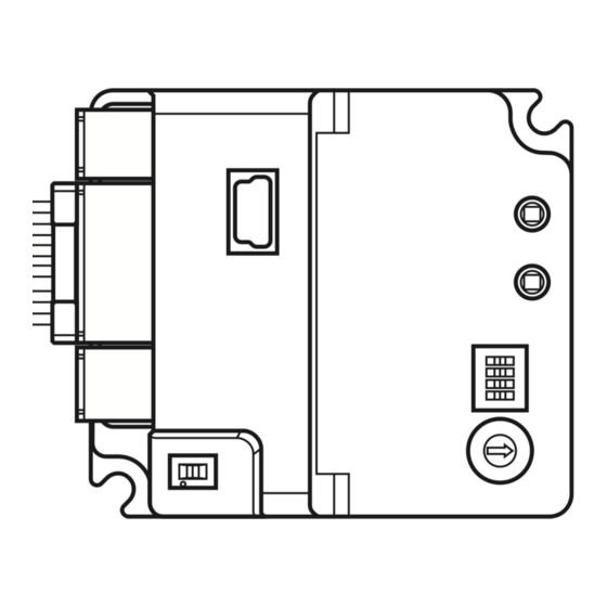
Preparation Names and functions of parts POWER/ALARM LED Function setting (Green/Red/Blue) switches (SW1) C-DAT/C-ERR LED Address number (Green/Red) setting switch (SW2) Heat sink USB communication connector Termination resistor setting switch (SW3) Cutouts (2 places) Power supply RS-485 communication connector (CN1) connector (CN3) Motor/encoder/ electromagnetic brake... -
Page 12: Indication Of Leds
Preparation Indication of LEDs The status of the driver and RS-485 communication can be checked using the indication of LEDs. The lighting colors of the POWER/ALARM LED and the C-DAT/C-ERR LED can be changed from green to white using the “LED (PWR/C-DAT) color changing” parameter. „... -
Page 13: Installation
Installation Installation Location for installation The driver is designed and manufactured to be incorporated in equipment. Install it in a well-ventilated location that provides easy access for inspection. The location must also satisfy the following conditions: • Inside an enclosure that is installed indoors (provide vent holes) •... - Page 14 Installation „ Dimensions [Unit: mm (in.)] Mass: 56 g (1.98 oz.) 47 (1.85) 3 (0.12) 41 (1.61) 0.25 (0.01) 24 (0.94) 2 (0.08)
-
Page 15: Connection
Main power supply Motor *1 It is an Oriental motor cable. Purchase is required separately. *2 Connecting the control power supply allows you to continue monitoring even if the main power supply is shut off. Connect it as necessary. *3 It is recommended that a circuit breaker or a circuit protector is connected because incorrect wiring may cause the internal input circuit to short-circuit. -
Page 16: Connecting The Main Power Supply And The Control Power Supply (Cn1)
Connection Connecting the main power supply and the control power supply (CN1) Connect a main power supply to the CN1 connector. Connecting the control power supply allows you to continue monitoring even if the main power supply is shut off. Connect it as necessary. - Page 17 Connection „ Internal input circuit The driver can be used with the main power supply and control power supply, or with the main power supply only. When using only the main power supply, the power is supplied from the main power supply to the control power supply circuit inside the driver.
-
Page 18: Connecting The Rs-485 Communication Cable (Cn3)
Connection Connecting the RS-485 communication cable (CN3) Connect the RS-485 communication cable to the CN3 connector. A cable to connect with the host controller and that to connect between drivers are required to be provided by the customer. Cables that connect to the network converter or the robot controller MRC01 are provided by Oriental Motor separately. - Page 19 Connection „ Internal input circuit GND of the power supply connector and SG of the RS-485 communication connector are electrically insulated. SW3 is a double-pole double-throw switch. Driver 1st unit RS-485 TR− TR− Driver 2nd unit TR− TR− Driver 31st unit TR−...
-
Page 20: Connecting The Usb Cable
• When relays or electromagnetic switches are used, use noise filters or CR circuits to suppress surge generated by them. • Use an Oriental Motor connection cable when extending the wiring distance between a motor and a driver. Refer to p.63 for the model name. This is effective in suppressing the electrical noise emitted from the motor. -
Page 21: Conformity To Emc
Install the following ferrite core (or equivalent) to the places shown in “Example of installation and wiring” on p.22. Part No.: ZCAT3035-1330 (TDK Corporation) z Connecting the motor cable Use an Oriental Motor connection cable when extending the wiring distance between a motor and a driver. Refer to p.63 for the model name. z Connecting the signal cable Refer to “Prevention of noise propagation”... - Page 22 *1 The driver is grounded by making the heat sink contact directly with the grounded panel. *2 An Oriental Motor cable is used. • The driver uses components that are sensitive to static electricity. Take measures against static electricity since static electricity may cause the driver to malfunction or suffer damage.
-
Page 23: Setting Of Switches
Setting of switches Setting of switches The figure shows the factory settings. When setting the switch, turn on the main power supply and the control power supply again. The new setting is enabled when the main power supply and the control power supply are turned on again. -
Page 24: Address Number (Slave Address)
Setting of switches Address number (slave address) Set the address number (slave address) by concurrently using the address number setting switch SW2 and the function setting switch SW1-No.1. Make sure each address number (slave address) having set for each driver is not duplicated. -
Page 25: Termination Resistor
Setting of switches „ When using the driver via industrial network The number of drivers that can be connected is 16 units maximum. Address number SW1-No.1 (slave address) Termination resistor Set a termination resistor to the driver located farthest (positioned at the end) from the host controller or the network converter. -
Page 26: Id Share Mode
Overview of ID share mode The ID share mode is Oriental Motor’s unique transmission mode in which multiple slaves share a communication ID. The master sends a query to multiple slaves. Each slave executes the processing and returns a response. - Page 27 ID share mode „ Overview of write When writing data in the ID share mode, an ID of data to be written is required to set in the “Share write data” parameter. Setting the ID of data to be written in the “Share write data” parameter can write a value using the “Share write data”...
-
Page 28: Flow Of Setting Of Id Share Mode
ID share mode When a query is sent from the master to the share group address 15, the slave addresses 1 and 2 start positioning operation. When each slave executes the processing, a response is returned sequentially. The order in which responses are returned is set in the “Share control local ID”... -
Page 29: Setting Of Share Group
ID share mode Setting of share group Set a group (share group) that operates in the ID share mode to the driver. The share group can be set with the unicast mode or the MEXE02. „ Related parameters Recalculation and setup are immediately executed when the parameter is written. Register address MEXE02 Initial... - Page 30 ID share mode z Setting flow 1. Send the following query in the unicast mode to set a share group to the driver of the slave address 1. Query (unicast mode) Field name Data Description Slave address Driver of slave address 1 Function code Writing to multiple holding registers Register address (upper)
-
Page 31: Setting Of Data To Be Read Or Written
ID share mode Setting of data to be read or written Set the data to be read in the “Share read data” parameter and the data to be written in the “Share write data” parameter. Data can be set with the unicast mode or the MEXE02. „... - Page 32 ID share mode Register address MEXE02 Initial Name Description Setting range code value Upper Lower 09BCh 09BDh Share write data 10 ID list (2492) (2493) Sets the ID of data to be Refer to the written in the ID share mode. 09BEh 09BFh next table.
- Page 33 ID share mode Name Description Sets the trigger for direct data operation. [Setting range] −7: Operation data number −6: Operation type −5: Position Direct data operation 0033h −4: Operating speed trigger −3: Starting/changing speed rate −2: Stopping deceleration −1: Operating current 0: Disable 1: All data updated Selects the stored area when the next direct data is...
- Page 34 ID share mode Name Description Indicates the time elapsed since the main power supply 00A1h Main power supply time was turned on in minutes. Indicates the number of times the control power supply 00A2h Control power supply count was turned on. 00A3h Inverter voltage Indicates the inverter voltage of the driver.
- Page 35 ID share mode z Setting flow 1. Send the following query in the unicast mode, and set the data to be read to the driver of the slave address 1. Query (unicast mode) Field name Data Description Slave address Driver of slave address 1 Function code Writing to multiple holding registers Register address (upper)
- Page 36 ID share mode „ Setting example of data to be written To set parameters, use “Writing to multiple holding registers (10h)” of the function code. This section explains an example that “Direct data operation operating speed, ” “Direct data operation starting/ changing rate, ”...
-
Page 37: Executing Read/Write
ID share mode Response (unicast mode) Field name Data Description Slave address Same as query Function code Same as query Register address (upper) Same as query Register address (lower) Data Number of registers (upper) Same as query Number of registers (lower) Error check (lower) Calculation result of CRC-16 Error check (upper) - Page 38 ID share mode „ Write Write the value (16 bits) using the “Share write data” area of the ID share register address. Up to 24 registers (24 x 16 bits) can be written. Write the upper and lower values at the same time. If not, an invalid value may be written. Write is executed in the order of ID share register addresses.
- Page 39 ID share mode Response (ID share mode) Field name Data Description Slave address Same as query Function code Same as query Number of data bytes Twice the number of registers in the query Value read from ID share register address (upper) Value read from ID share register address 0000h = Present alarm (upper): 0000h Value read from ID share register address (lower)
- Page 40 ID share mode „ Example of write Write “Direct data operation operating speed, ” “Direct data operation starting/changing rate, ” and “Direct data operation stopping deceleration” to the slave addresses 1 and 2. Slave address 1 Slave address 2 Description ID share register address Value Corresponding...
- Page 41 ID share mode Field name Data Description Value written to ID share register address Value write to ID share register address (upper) 0000h = Direct data operation operating Value write to ID share register address (lower) speed (upper): 0000h Value written to ID share register address Value write to ID share register address +1 (upper) 0001h = Direct data operation operating Value write to ID share register address +1 (lower)
- Page 42 ID share mode „ Example of read/write Write values to “Direct data operation operating speed, ” “Direct data operation starting/changing rate, ” and “Direct data operation stopping deceleration” first, and read “Present alarm, ” “Driver temperature, ” and “Motor temperature. ” Slave address 1 Slave address 2 Description...
- Page 43 ID share mode Field name Data Description Value written to ID share register address Value write to ID share register address (upper) 0000h = Direct data operation operating Value write to ID share register address (lower) speed (upper): 0000h Value written to ID share register address Value write to ID share register address +1 (upper) 0001h = Direct data operation operating Value write to ID share register address +1 (lower)
- Page 44 ID share mode Response (ID share mode) Field name Data Description Slave address Same as query Function code Same as query (Read) Number of data bytes Twice the number of registers in the query Value read from ID share register address (upper) Value read from ID share register address 0000h = Present alarm (upper): 0000h Value read from ID share register address (lower)
- Page 45 ID share mode Field name Data Description Error check (lower) Calculation result of CRC-16 Error check (upper) *1 Slave address 1 (Share control local ID: 1) *2 Slave address 2 (Share control local ID: 2) *3 Whenever data is sent to each slave, error check is performed on the data having sent until then.
-
Page 46: Addresses And Codes Lists
Addresses and codes lists Addresses and codes lists Refer to the AZ Series OPERATING MANUAL Function Edition for addresses and codes not described in this chapter. This chapter describes the following. • Addresses and codes specific to the mini Driver •... - Page 47 Addresses and codes lists Modbus Industrial communication Name Description network Register address Command code Upper Lower 017Eh 017Fh Indicates the ON-OFF status of the internal I/O. 20BFh I/O status 8 (382) (383) (Arrangement of bits “I/O status”) (8383) 0A0Ah 0A0Bh Alarm history details Indicates the description of the alarm history specified by 2505h...
- Page 48 Addresses and codes lists Modbus Industrial communication Description network Register address Command code Bit 15 Bit 14 Bit 13 Bit 12 Bit 11 Bit 10 Bit 9 Bit 8 0174h (372) Bit 7 Bit 6 Bit 5 Bit 4 Bit 3 Bit 2 Bit 1 Bit 0...
- Page 49 Addresses and codes lists Modbus Industrial communication Description network Register address Command code Bit 15 Bit 14 Bit 13 Bit 12 Bit 11 Bit 10 Bit 9 Bit 8 D-END7 D-END6 D-END5 D-END4 D-END3 D-END2 D-END1 D-END0 017Ch (380) Bit 7 Bit 6 Bit 5 Bit 4...
- Page 50 Addresses and codes lists „ Parameter R/W commands Timing to update parameters are shown in the table. In this manual, each update timing is represented in an alphabet. Notation Update timing Description Recalculation and setup are immediately executed when the parameter is Update immediately written.
- Page 51 Addresses and codes lists z LED status indication setting parameters Modbus Industrial network communication Command code Name Description Update Register address Upper Lower READ WRITE Sets the number of times that the C-DAT/C-ERR LED blinks in green when 03D0h 03D1h Number of times the GREEN the main power supply is turned on.
-
Page 52: Addresses And Codes Not Compatible With The Mini Driver
Addresses and codes lists z RS-485 communication setting parameter Modbus Industrial network communication Command code Name Description Update Register address Upper Lower READ WRITE When the RS-485 communication error has occurred for the set number of times, an alarm of RS-485 communication error is 138Ch 138Dh Communication error... -
Page 53: I/O Signals Assignment List
Addresses and codes lists „ Driver mode setting parameters Modbus communication Industrial network Register address Command code Name Upper Lower READ WRITE 03E0h 03E1h 01F0h 11F0h PULSE-I/F mode selection (992) (993) (496) (4592) I/O signals assignment list „ Input signals To assign signals via industrial network, use the “assignment numbers”... - Page 54 Addresses and codes lists „ Output signals To assign signals via industrial network, use the “assignment numbers” in the table instead of the signal names. Assignment Assignment Assignment Signal name Signal name Signal name number number number Not used FW-POS_R ABSPEN FREE_R RV-POS_R...
- Page 55 Addresses and codes lists Assignment Signal name number D-END1 D-END2 D-END3 D-END4 D-END5 D-END6 D-END7 INFO-USRIO INFO-POSERR INFO-DRVTMP INFO-MTRTMP INFO-OVOLT INFO-UVOLT INFO-OLTIME INFO-SPD INFO-START INFO-ZHOME INFO-PR-REQ INFO-EGR-E INFO-RND-E INFO-NET-E INFO-FW-OT INFO-RV-OT INFO-CULD0 INFO-CULD1 INFO-TRIP INFO-ODO INFO-DSLMTD INFO-IOTEST INFO-CFG INFO-RBT...
-
Page 56: 10 Inspection And Maintenance
Inspection It is recommended that periodic inspections are conducted for the items listed below after each operation of the motor. If an abnormality is found, discontinue any use and contact your nearest Oriental Motor sales office. „ Inspection item • Check if the openings in the driver are clogged. -
Page 57: 11 Troubleshooting
Troubleshooting 11 Troubleshooting 11-1 Detection of communication errors This driver has functions to detect abnormalities that may occur in communication, including two types: communication errors and alarms. „ Communication errors If a communication error of the RS-485 communication error (error code 84h) occurs, the C-DAT/C-ERR LED will be lit in red and the POWER/ALARM LED will blink in blue. - Page 58 Troubleshooting Error Type of Cause Remedial action code communication error The setting data requested by the host Out of setting range controller could not be executed due Check the setting data. to out of range. Command execute When the command is unable to Check the driver status.
-
Page 59: Alarm
Contact your nearest Oriental Motor sales office. * It is 36 VDC when the “Main power mode” parameter is set to “24 VDC, ” and 63 VDC when it is set to “48 VDC. ”... -
Page 60: Information
Troubleshooting 11-3 Information The driver is equipped with a function to generate information output before an alarm is generated. If information is generated, the POWER/ALARM LED blinks in blue. This section explains information specific to the mini Driver. Refer to the AZ Series OPERATING MANUAL Function Edition when information not included here is generated. -
Page 61: Troubleshooting And Remedial Actions
In motor operation, the motor or the driver may not operate properly due to an improper setting or wrong connection. When the motor cannot be operated properly, refer to the contents provided in this chapter and take an appropriate remedial action. If the problem persists, contact your nearest Oriental Motor sales office. Phenomenon Possible cause Remedial action •... - Page 62 Troubleshooting Phenomenon Possible cause Remedial action Lower the current with the “Base current” parameter. If The load is small. the motor output torque is too large with respect to a load, vibration will increase. The “Main power mode” parameter Check the setting of the “Main power mode” Motor vibration is too large.
-
Page 63: 12 Cables
Cables 12 Cables 12-1 Connection cables „ Connection cables/Flexible connection cables (For AZM14, AZM15, AZM24, AZM26) These cables are used when connecting a motor and a driver. Connection cable When installing the motor on a moving part, use a flexible cable. z Connection cables z Flexible connection cables For motor/encoder... - Page 64 Cables „ Connection cables/Flexible connection cables (For AZM46, AZM48, AZM66, AZM69) These cables are used when connecting a motor and a driver. The figure shows an example when the electromagnetic brake motor is used. Connection cable When installing the motor on a moving part, use a flexible cable. z Connection cables For motor/encoder For motor/encoder/electromagnetic brake...
-
Page 65: Rs-485 Communication Cables
Cables „ Extension cables/Flexible extension cables These cables are used when extending a connection cable (add between the driver and connection cable). Use if the length of the connection cable used is not enough when extending the distance between a motor and a driver. -
Page 66: 13 Reference Materials
Reference materials 13 Reference materials 13-1 Timing chart „ Power activation z When a control power supply is not connected 10 s or more Main power supply 1 s or less 1 s or less SYS-RDY Fixed (output is set, and input is enabled) Not xed 1 s or less 1 s or less... - Page 67 Reference materials z When a control power supply is connected 10 s or more Control power supply 1 s or less 1 s or less SYS-RDY Fixed (output is set, and input is enabled) Not xed 1 s or less 1 s or less Ready RS-485 communication preparation...
-
Page 68: Specifications
Reference materials 13-2 Specifications „ Product specifications 24 VDC±5 % Rated voltage 48 VDC±5 % Main power supply Input current 0.4 to 3.7 A *1 24 VDC input: 20 to 32 VDC (22.8 to 32 VDC) *2 Allowable operating voltage 48 VDC input: 40 to 55 VDC 24 VDC±5 % Rated voltage... - Page 72 If a new copy is required to replace an original manual that has been damaged or lost, please contact your nearest Oriental Motor sales office. • Oriental Motor shall not be liable whatsoever for any problems relating to industrial property rights arising from use of any information, circuit, equipment or device provided or referenced in this manual.
Need help?
Do you have a question about the ASTEP AZ Series and is the answer not in the manual?
Questions and answers