Table of Contents
Advertisement
Aura Series
(PP-7000II / PP-7200L / PP-7000U /
PP-7200U) THERMAL PRINTER
USER'S MANUAL
FCC Notes:
This equipment generates, uses, and can radiate radio frequency energy and, if not installed and
used in accordance with the instructions manual, may cause interference to radio communications.
It has been tested and found to comply with limits for a Class A digital device pursuant to subpart
J of Part 15 of FCC Rules, which are designed to provide reasonable protection against
interference when operated in a commercial environment. Operation of this equipment in a
residential area is likely to cause interference in which case the user at his own expense will be
required to take whatever measures to correct the interference.
CE manufacturer's Declaration of Conformity
(EC Council Directive 89/336/EEC of 3 May 1989)
This product has been designed and manufactured in accordance with the International Standards
EN50081-1/01.92 and EN50082-1/01.92 following the provisions of the Electro Magnetic
Compatibility Directive of the European Communities as of May 1989
Warranty Limits:
Warranty terminates automatically when any person other than the authorized technicians opens
the machine. The user should consult his/her dealer for the problem happened. Warranty voids if
the user does not follow the instructions in application of this merchandise. The manufacturer is by
no means responsible for any damage or hazard caused by improper application.
About This Manual:
Posiflex has made every effort for the accuracy of the content in this manual. However, Posiflex
will assume no liability for any technical inaccuracies or editorial or other errors or omissions
contained herein, nor for direct, indirect, incidental, consequential or otherwise damages, including
without limitation loss of data or profits, resulting from the furnishing, performance, or use of this
material.
This information is provided "as is" and Posiflex Technologies, Inc. expressly disclaims any
warranties, expressed, implied or statutory, including without limitation implied warranties of
merchantability or fitness for particular purpose, good title and against infringement.
The information in this manual contains only essential hardware concerns for general user and is
subject to change without notice. Posiflex reserves the right to alter product designs, layouts or
drivers without notification. The system integrator shall provide applicative notices and
arrangement for special options utilizing this product. The user may find the most up to date
information
of
the
http://www.posiflex.com.tw or http://www.posiflexusa.com
All data should be backed-up prior to the installation of any drive unit or storage peripheral.
Posiflex will not be responsible for any loss of data resulting from the use, disuse or misuse of this
or any other Posiflex product.
All rights are strictly reserved. No part of this documentation may be reproduced, stored in a
retrieval system, or transmitted in any form or by any means, electronic, mechanical, photocopying,
or otherwise, without prior express written consent from Posiflex Technologies, Inc. the publisher
of this documentation.
© Copyright Posiflex Technologies, Inc. 2008
All brand and product names and trademarks are the property of their respective holders.
P/N: 19370902010
hardware
from
web
Rev.: D1
sites:
http://www.posiflex.com
or
Part 1
Advertisement
Table of Contents

Related Manuals for POSIFLEX PP-7200L


Summary of Contents for POSIFLEX PP-7200L
- Page 1 Aura Series (PP-7000II / PP-7200L / PP-7000U / PP-7200U) THERMAL PRINTER USER’S MANUAL FCC Notes: This equipment generates, uses, and can radiate radio frequency energy and, if not installed and used in accordance with the instructions manual, may cause interference to radio communications.
-
Page 2: Getting Started
The Aura PP-7000II series support two types of interface input through different sub-codes to the model number. The interfaces are RS232 for serial interface and Centronics for parallel interface. The Aura PP-7200L series connects to a LAN port of Posiflex POS systems. The Aura PP-7000U series... - Page 3 UNPACKING Followings are items you may find when you carefully unpack the carton that delivers Aura series printer. If there is any discrepancy or problem, contact your dealer immediately. Be sure to save the packing materials in case the printer needs to be shipped at some point in the future.
-
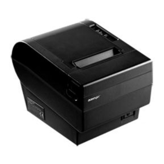
Page 4: Product Pictures
Top Cover Hood Release Front View Front View Window Plate Screw Setup Window Power Switch Rear View PP-7000II PP-7200L Power LED Error LED Bottom View Bottom View Cable Cover Screw Hole PP-7000U PP-7200U Paper Out LED FEED Switch Cutter Cover... - Page 5 The numbered items above are: Power Connector Parallel Connector Frame Ground Peripheral Connector Serial Connector Interface Bracket Screw USB Connector LAN Connector Reset Pin Hole 10). Service Serial Port Cable Cover INDICATORS Power LED: green Error LED: red Paper Out LED: red Tenon Screw Hole Tenon...
-
Page 6: Quick Start-Up
Pix. 3. Tear off excessive paper. When to Replace Paper Whenever the printer gives paper out signal or a red line appears on the thermal paper, it is the proper timing for replacing the paper. Do not wait till the print engine is dragging the paper roll at the very end. - Page 7 The LAN connector is a 8-PIN RJ45 connector in middle left of the connector area for PP-7200L. Please use a LAN cable of CAT 5 with proper length to connect the LAN connector on the printer to the LAN HUB as appropriate.
- Page 8 PP-7000II or between the peripheral connector and the B type USB connector for PP-7200U and is at the rightmost for PP-7000U & PP-7200L. Either a Posiflex supplied power adaptor or a printer power cable from a Posiflex POS system can be connected to this connector to supply power for this printer.
-
Page 9: Special Adjustments
Install Cable Cover Check the bottom view of the printer, the 4 screws for the printer itself are in quite deep holes. Insert the tenons of the cable cover into the 2 printer screw holes nearest to the connection area. Apply a cable cover fixing screw at the matched screw holes as circled in the bottom view picture at right. - Page 10 signal.
-
Page 11: Installing Driver
However, DHCP is not supported. Reset Pin Hole As the LAN setup for the PP-7200L can be set freely, if the changes are not well registered some troubles could be introduced. Therefore, in PP- 7200L, there is a “Reset pin hole” near the LAN connector. Use something like... -
Page 12: General Cleaning
GENERAL CLEANING Please use soft hairbrush or compressed air to clear away any dust or paper scraps accumulation inside the printer. Check also the area of the auto- cutter regularly. PRINT HEAD CLEANING The print head is located underneath the roll paper passage at the exit as in the picture below. - Page 13 If there is no paper jam and the print head is not overheated, turn off the printer and wait for half a minute then turn it back on. If the problem still remains, contact a qualified service person.
- Page 14 Turn this wheel downward for 4 or 5 strokes. Aim the guide of the cutter cover and push it back to position to close the cutter cover and turn the printer power on to see if the auto cutter lock up problem is resolved.
-
Page 15: Useful Tips
Advanced Analysis Tool This printer supports Hexadecimal Dump for experienced user to view exactly what data is received by the printer. This can be useful in finding software problems. To start the dump mode: Turn off printer; Open print hood; Hold down FEED button while turning printer on;... - Page 16 Do not set any liquid or drinks such as coffee on the printer case. Do not touch any metal part to avoid possible electrostatic damage. Do not touch the areas around the print head and motor during or right after printing.
-
Page 17: Specifications
SPECIFICATIONS PRINTER ITEM Printing method Effective printing width Thermal head configuration Printing speed Paper feed method Paper load method Auto-cutter capability Manual cutter Dot Pitch Input power type Input voltage Dimension (mm) Weight PAPER PAPER TYPE Paper roll formation Paper width... - Page 18 Switch position 4 defines the handshaking method in serial interface. When it is set to ON, the printer transmits an “XOFF” for busy and sends an “XON” for not busy. When it is set to OFF, the printer signifies the busy status over hardware signals that can be detected by the host as “DSR”...
-
Page 19: Internal Switch
Paper End (completely no paper) till paper is replaced when S1-5 is ON. Yet when S1-5 is OFF, the printer will keep on beeping every 3 seconds at Paper Near End (still long paper in replace) till paper is replaced. - Page 20 Switch position 2 is usually set to OFF for use with 80 mm paper width. When the printer is installed with the 58 mm paper guide adaptor for use with the paper roll of 58 mm width, the switch should be set to ON.
Need help?
Do you have a question about the PP-7200L and is the answer not in the manual?
Questions and answers