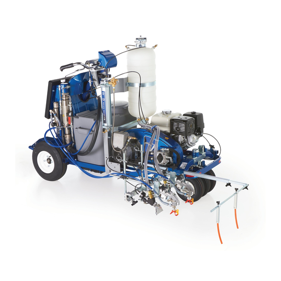
Graco LineLazer V250SPS Manual
Steering cable replacement
Hide thumbs
Also See for LineLazer V250SPS:
- Repair parts (72 pages) ,
- Operation (42 pages) ,
- Repair parts (78 pages)
Advertisement
Repair
Steering Cable Replacement Instructions
for LineLazer V 250
For steering cable replacement on self-propelled line striper.
Both cables must always be replaced, even if only one failed.
For Models: 17H471, 17H472, 17H473, 25P365, 17H474, 17H466, 17H467, 17H468, 17J951, and 17H469
Important Safety Instructions
Read all warnings and instructions in this
manual before using the equipment. Be
familiar with the controls and the proper
usage of the equipment. Save these
instructions.
Related Manuals:
3A3393
Operation
Use only genuine Graco replacement parts.
The use of non-Graco replacement parts may void warranty.
and 250
SPS
DC
ti23089a
3A6981C
EN
Advertisement
Table of Contents

Summary of Contents for Graco LineLazer V250SPS
- Page 1 Be familiar with the controls and the proper usage of the equipment. Save these instructions. Related Manuals: 3A3393 Operation ti23089a Use only genuine Graco replacement parts. The use of non-Graco replacement parts may void warranty.
- Page 2 • Check hoses and parts for signs of damage. Replace any damaged hoses or parts. • This system is capable of producing 3300 psi. Use Graco replacement parts or accessories that are rated a minimum of 3300 psi. • Always engage the trigger lock when not spraying. Verify the trigger lock is functioning properly.
-
Page 3: Pressure Relief Procedure
Pressure Relief Procedure Pressure Relief 2. Turn pressure control to lowest setting. Trigger all guns to relieve pressure. Procedure ti3305a ti3441a PAINT 3. Engage all gun trigger locks. Turn prime valve(s) down (250 has one prime valve; 250 has two This equipment stays pressurized until pressure is prime valves). -
Page 4: Steering Cable Replacement
Steering Cable Replacement Steering Cable Replacement Removal 3. Remove six screws and control shroud. NOTE: Both cables must always be replaced, even if only one failed. Repeat steps 5-7 for each cable. 1. Perform Pressure Relief Procedure, page 3. 2. Loosen four screws and remove pad. ti23930a ti23931a 3A6981C Repair... - Page 5 Steering Cable Replacement 4. Apply parking brake. Raise front wheel off the 6. On front wheel fork, remove locknut (3) and ball joint ground and support frame on two jack stands. (40) from fork. Remove ball joint (40) from cable (48) and save if not replacing.
- Page 6 Steering Cable Replacement Installation 5. At handle bar, install ball joint (40) on cable (48) and match threads on other side of handle bar. Install ball joint (40) into handlebar and tighten locknut (3). Both cables must always be replaced, even if only one failed.
- Page 7 Steering Cable Replacement 8. Verify handlebar is aligned straight with the frame. If 10. Mark the front adjustment nut (50) to note current misaligned, turn adjustment nut (49) to straighten position, then back off three full rotations. Tighten the handle. rear adjustment nut (49) until frame is secured between both adjustment nuts.
-
Page 8: Graco Standard Warranty
With the exception of any special, extended, or limited warranty published by Graco, Graco will, for a period of twelve months from the date of sale, repair or replace any part of the equipment determined by Graco to be defective.


Need help?
Do you have a question about the LineLazer V250SPS and is the answer not in the manual?
Questions and answers