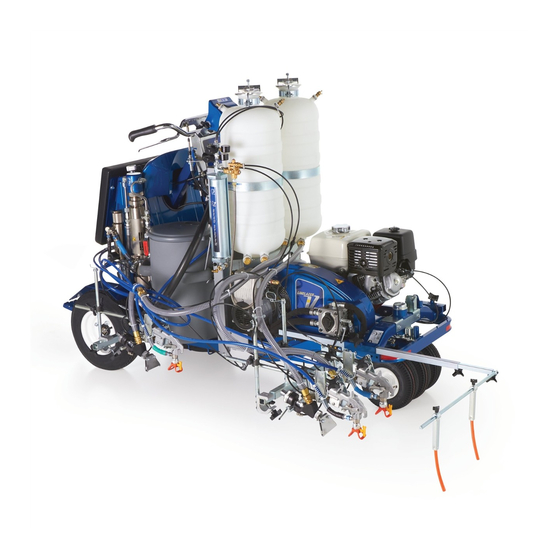
Graco LineLazer V 250SPS Operation
Self-propelled line striper, for the application of line striping materials, for professional use only, for outdoor use only, not for use in explosive atmospheres or hazardous locations, maximum operating speed: 10 mph 16 kph, maximum operating pressure:
Hide thumbs
Also See for LineLazer V 250SPS:
- Repair parts (72 pages) ,
- Manual (8 pages) ,
- Repair parts (21 pages)
Table of Contents
Advertisement
Operation
LineLazer V 250
Self-Propelled Line Striper
For the application of line striping materials.
For professional use only.
For outdoor use only.
Not for use in explosive atmospheres or hazardous locations.
Maximum Operating Speed: 10 mph (16 kph)
Maximum Operating Pressure: 3300 psi (22.8 MPa, 228 bar)
Important Safety Instructions
Read all warnings and instructions in this manual and in related manuals.
Be familiar with the controls and the proper usage of the equipment.
Save these instructions.
Pressurized
Model
Guns
Bead System Description
17H471
2
No
17H472
3
No
17H473
2
Yes - 2 Tank LLV 250
17H474
3
Yes - 2 Tank LLV 250
17H466
1
No
17H467
2
No
17H468
1
Yes - 1 Tank LLV 250
17J951
2
Yes - 1 Tank LLV 250
17H469
2
Yes - 2 Tank LLV 250
Related Manuals:
3A3394
Repair / Parts
311254
Gun
309277
Pump
3A3428
Auto-Layout Applications Methods
332230
Pressurized Bead System (PBS)
Use only genuine Graco replacement parts.
The use of non-Graco replacement parts may void warranty.
and 250
SPS
LLV 250
DC
LLV 250
DC
DC
DC
LLV 250
SPS
LLV 250
SPS
SPS
SPS
SPS
DC
3A3393C
EN
Advertisement
Table of Contents

Related Manuals for Graco LineLazer V 250SPS


Summary of Contents for Graco LineLazer V 250SPS
- Page 1 17H469 Yes - 2 Tank LLV 250 Related Manuals: 3A3394 Repair / Parts 311254 309277 Pump 3A3428 Auto-Layout Applications Methods 332230 Pressurized Bead System (PBS) Use only genuine Graco replacement parts. The use of non-Graco replacement parts may void warranty.
-
Page 2: Table Of Contents
Technical Specifications ....38 Graco Standard Warranty ....42... -
Page 3: Warnings
• Check hoses and parts for signs of damage. Replace any damaged hoses or parts. • This system is capable of producing 3300 psi. Use Graco replacement parts or accessories that are rated a minimum of 3300 psi. • Always engage the trigger lock when not spraying. Verify the trigger lock is functioning properly. - Page 4 Warnings CARBON MONOXIDE HAZARD Exhaust contains poisonous carbon monoxide, which is colorless and odorless. Breathing carbon monoxide can cause death. • Do not operate in an enclosed area. EQUIPMENT MISUSE HAZARD Misuse can cause death or serious injury. • Do not operate the unit when fatigued or under the influence of drugs or alcohol. •...
- Page 5 Warnings TOXIC FLUID OR FUMES HAZARD Toxic fluids or fumes can cause serious injury or death if splashed in the eyes or on skin, inhaled, or swal- lowed. • Read Safety Data Sheet (SDS) to know the specific hazards of the fluids you are using. •...
-
Page 6: Battery Disposal
Warnings Battery Disposal Do not place batteries in the trash. Recycle batteries according to local regulations. To find a recycling location in the USA and Canada call 1-800-822-8837 or go to www.call2recycle.org. ti25930a 3A3393C Operation... -
Page 7: Component Identification (Llv 250Dc Shown)
Component Identification (LLV 250DC Shown) Component Identification (LLV 250 Shown) 10 Serial label under operator platform Paint filter, both sides 11 Rear gun arm mount, both sides Adjustable pad 12 Hydraulic fill cap/dipstick Engine fuel cap 13 Prime/drain valve, both sides Wheel motor bypass valve 14 Handle bar height adjustment knob Straight line adjuster... -
Page 8: Component Identification (Controls)
Component Identification (Controls) Component Identification (Controls) ti23143a 12V accessory jack Gun trigger control Engine key switch, OFF - ON - Start Gun 1, 2, 3 selector Engine clutch switch Display 10 Engine choke Forward/reverse lever 11 Engine throttle Pressure control Hydraulic pump valve, both sides 3A3393C Operation... -
Page 9: Grounding Procedure (For Flammable Flushing Fluids Only)
Grounding Procedure (For Flammable Flushing Fluids Only) Grounding Procedure 1. Perform Grounding Procedure if using flammable materials. (For Flammable Flushing Fluids 2. Set pump valve(s) to OFF (250 has one pump Only) valve; 250 has two pump valves). Turn engine OFF. -
Page 10: Setup/Startup
Setup/Startup Setup/Startup 6. Set pump valve(s) to OFF (250 has one pump valve; 250 has two pump valves). This equipment stays pressurized until pressure is manually relieved. To help prevent serious injury from pressurized fluid, such as skin injection, splash- ing fluid and moving parts, follow the Pressure Relief ti23 Procedure when you stop spraying and before clean-... - Page 11 Setup/Startup 10. Apply brake. d. Turn engine key switch clockwise to START. ti18550a START 11. Start engine: a. Move fuel valve to open. ti23147a e. After engine starts, move choke to open. ti3312a b. Move choke to closed. ti18563a 12. Set engine clutch switch to ON. ti18561a c.
-
Page 12: Switchtip And Guard Assembly
Setup/Startup 14. Set pump valve(s) ON (250 has one pump 18. Inspect fittings for leaks. If leaks occur, turn sprayer valve; 250 has two pump valves). Pumps are now OFF immediately. Perform Pressure Relief Proce- active. dure. Tighten leaky fittings. Repeat Startup, steps 1 - 17. -
Page 13: Gun Placement
Gun Placement Gun Placement Install Guns Select Guns (Standard Series) 1. Insert guns into gun holder. Tighten clamps. 3. Use the three gun selector switches to determine which guns are active. Each gun selector switch has 3 positions: programmed line pattern, OFF, and continuous line. -
Page 14: Gun Positions Chart
Gun Placement Gun Positions Chart ti23154a One line One line up to 24 in. (61 cm) wide Two lines One line with two line highlight (250 only) Two lines with three line highlight (250 only) One gun curb Two gun curb 3A3393C Operation... -
Page 15: Gun Arm Mounts
Gun Placement Gun Arm Mounts 4. Tighten gun arm knob into gun arm mounting slot. This unit is equipped with front and rear gun arm mounts on either side. ti28203a NOTICE Make sure all hoses, cables, and wires are properly routed through brackets and do NOT rub on tire. -
Page 16: Installation
Gun Placement Installation 2. Install exposed cable through cable bracket slot. 1. Install vertical gun mount onto gun bar. ti18997a 3. Insert plastic cable retainer into cable bracket hole. ti28206a NOTE: Make sure all hoses, cables, and wires are properly routed through brackets. Gun Cable Adjustment Adjusting the gun cable will increase or decrease the ti23151a... -
Page 17: Change Trigger Position
Gun Placement Change Trigger Position Removal Installation 1. Remove both hand grips from handle bar (spraying 1. Route trigger wire to other side of handle bar. Make compressed air into end of handle grip works well sure wire is routed behind steering column, through for this). -
Page 18: Cleanup
Cleanup Cleanup 4. Clean filter, guard and SwitchTip in flushing fluid. This equipment stays pressurized until pressure is manually relieved. To help prevent serious injury from pressurized fluid, such as skin injection, splash- ing fluid and moving parts, follow the Pressure Relief TI3375A FLUSH Procedure when you stop dispensing and before... -
Page 19: Driving Instructions
Driving Instructions Driving Instructions To stop: Release control lever and allow it to return to center. Perform startup see, Setup/Startup, page 10. ti23157a Use the handle bars of the LineStriper to control all To turn right and left: Turn the handle bar right or left motion during operation. -
Page 20: Parking/Emergency Brake
Driving Instructions Parking/Emergency Brake Straight Line Adjustment This unit is equipped with a parking brake. Always The front wheel is set to center the unit and allow the engage parking brake when not in operation. Brake may operator to form straight lines. Over time, the wheel may also be used to slow machine in an emergency situa- become misaligned and will need to be readjusted. -
Page 21: Handle Bar Height Adjustment
Driving Instructions Handle Bar Height Adjustment 2. To lower stand, pull pin and lower stand. 1. Loosen handlebar height adjuster lock. ti18566a ti23160a Front Pad Adjustment 2. Raise or lower handlebars to desired height. 1. Loosen four bolts. 2. Slide pad up or down to desired position. ti23161a 3. -
Page 22: Smart Control Operation
Smart Control Operation Smart Control Operation Menu Tree 3A3393C Operation... -
Page 23: Control Features
Smart Control Operation Control Features ti23788a Ref. Switch / Indicator Explanation Menu Controls Provides menu specific commands as displayed on LCD screen. Provides skipline paint and space distance storage for instant change. Press and hold button to store pattern. Selects preset values “Favorite”... -
Page 24: Main Menus
Smart Control Operation Main Menus Use MENU buttons to scroll thorough the four main menus. Striping Mode See Striping Mode (LLV 250DC Shown), page 27 for features. LLV 250 shown LLV 250 displays information for only 1 pump. Measure Mode See Measure Mode, page 28 for features. -
Page 25: Initial Setup
Smart Control Operation Initial Setup SI Units Pressure = bar (MPa available) Volume = liters The initial setup prepares the striper for operation based Distance = meters on a number of user entered parameters. Language Line thickness = micron (g/m available) selections and the units of measure selections can be Paint Specific Gravity = Use UP and DOWN arrows... - Page 26 Smart Control Operation 5. Extend steel tape to distance greater than 26 ft. 9. Push gun trigger control to start calibration. (8m). ti18716a 25 ft ti18564c 10. Move striper forward. Keep unit aligned with steel 6. Press to select Setup/Information. tape.
-
Page 27: Striping Mode (Llv 250Dc Shown)
Smart Control Operation Striping Mode (LLV 250 Shown) ti23819a Ref. Description Ref. Description 1 Exits and returns to the Striping Mode Menu. Select a “Favorite”, press for less than one sec- ond. 2 Select switch 1, 2, or 3. Save a “Favorite”, press and hold for more than 3 Line Width Adjustment, if switch is operating more three seconds. -
Page 28: Measure Mode
Smart Control Operation Measure Mode 2. Press and release gun trigger control. Move striper forwards or backwards. (Moving backwards is a negative distance.) Measure Mode replaces a tape measure to measure distances when laying out an area to be striped. 1. -
Page 29: Layout Mode
Smart Control Operation Layout Mode 2. Press and release gun trigger control and move striper forward. Layout Mode is used to calculate and mark parking lot stalls. 1. Use to select Layout Mode. ti18564b ti23820a *LLV 250 displays information for only 1 pump. Ref. -
Page 30: Stall Calculator
Smart Control Operation Stall Calculator 2. The most recent length measured in Measure Mode is displayed or press gun trigger control to start a new measurement. Press again to stop measuring. Stall Calculator is used to set the stall size. The striper divides the measured length by the stall size to deter- Stall size and calculated number of stalls are both mine the number of stalls that will fit in the length mea-... -
Page 31: Angle Calculator
Smart Control Operation Angle Calculator 3. Measure and mark the offset distance (z) calculated for the first stall. Angle Calculator is used to determine the offset value and dot spacing value for a layout. 1. Use to select Layout Mode. Press open Angle Calculator Menu. -
Page 32: Setup/Information
Smart Control Operation Setup/Information to select Setup/Information. Press to select Language. See Language, page 25. See Calibration, page 25. See Units, page 25. See Information, page 33. See Marker Layout Mode, page 35. 3A3393C Operation... -
Page 33: Information
Smart Control Operation Information to select Setup/Information. Press open Information Menu. Displays and logs life data and striper information. Logs last four error codes that occurred. Code Description 02 = Over pressure on sensor #1 03 = No transducer #1 detected 22 = Over pressure on sensor #2 23 = No transducer #2 detected Set time and date using arrow keys. -
Page 34: Information (2)
Smart Control Operation Information (2) to select Setup/Information. Press open Information Menu. Press to open Information (2) Menu. Set low speed limit (X) and high speed limit (Y). If you travel outside of these speeds while striping the striper will beep. Fast beep if traveling above the limit and a slow beep if traveling below the limit. - Page 35 Smart Control Operation Marker Layout Mode 4. Set gun switch to skip line. The Measure Mode feature sprays a dot or a series of dots to mark an area. 1. Use to select Setup/Information. Press to open Marker Layout Mode. 5.
-
Page 36: World Symbol Key
World Symbol Key World Symbol Key 3A3393C Operation... -
Page 37: Hydraulic Oil/Filter Change
1. Apply a light film of oil on filter gasket. Install drain plug and oil filter. Tighten oil filter 3/4 turn after gas- ket contacts base. 2. Fill with five quarts of Graco hydraulic oil 169236 (5 gallon/20 liter) or 207428 (1 gallon/3.8 liter). This equipment stays pressurized until pressure is 3. -
Page 38: Technical Specifications
Technical Specifications Technical Specifications LineLazer V 250 (Models 17H471, 17H472) U.S. Metric Dimensions Height (with handle bar down) Unpackaged - 50.5 in. Unpackaged - 128.3 cm Packaged - 63.5 in. Packaged - 161.3 cm Width Unpackaged - 33.0 in. Unpackaged - 83.8 cm Packaged - 45.0 in. - Page 39 Technical Specifications LineLazer V 250 with Pressurized Bead System (Models 17H473, 17H474) U.S. Metric Dimensions Height (with handle bar down) Unpackaged - 55.7 in. Unpackaged - 141.5 cm Packaged - 63.5 in. Packaged - 161.3 cm Width Unpackaged - 33.0 in. Unpackaged - 83.8 cm Packaged - 45 in.
- Page 40 Technical Specifications LineLazer V 250 (Models 17H466, 17H467) U.S. Metric Dimensions Height (with handle bar down) Unpackaged - 55.7 in. Unpackaged - 141.5 cm Packaged - 63.5 in. Packaged - 161.3 cm Width Unpackaged - 33.0 in. Unpackaged - 83.8 cm Packaged - 45 in.
- Page 41 Technical Specifications LineLazer V 250 with Pressurized Bead System (Models 17H468, 17J951, 17H469) U.S. Metric Dimensions Height (with handle bar down) Unpackaged - 55.7 in. Unpackaged - 141.5 cm Packaged - 63.5 in. Packaged - 161.3 cm Width Unpackaged - 33.0 in. Unpackaged - 83.8 cm Packaged - 45 in.
-
Page 42: Graco Standard Warranty
With the exception of any special, extended, or limited warranty published by Graco, Graco will, for a period of twelve months from the date of sale, repair or replace any part of the equipment determined by Graco to be defective.
Need help?
Do you have a question about the LineLazer V 250SPS and is the answer not in the manual?
Questions and answers