Table of Contents
Advertisement
Quick Links
Operation/Parts
HVLP Sprayers
For professional use only. For portable spray applications of fine finish coatings.
Not approved for use in explosive atmospheres or hazardous locations.
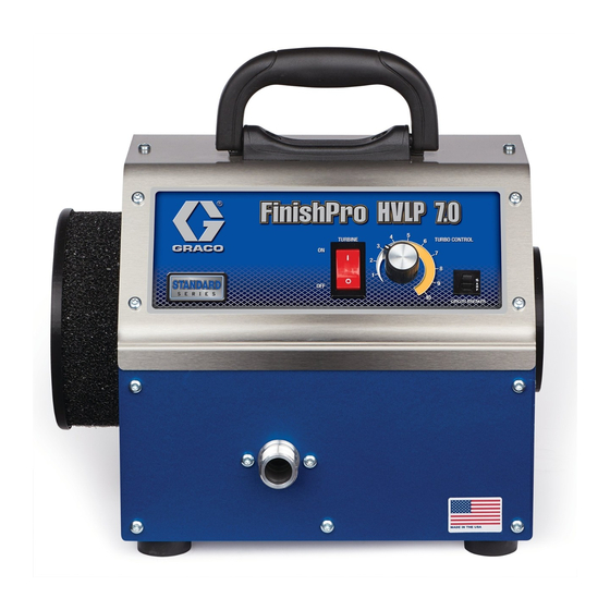
HVLP 7.0/9.0 Standard
HVLP 7.0/9.0/9.5 ProContractor
HVLP 9.5 ProComp
See page 3 for additional model information
1
0 psi (0.07 MPa, 0.7 bar) Maximum Working Pressure
ProComp Models: 50 psi (0.35MPa, 3.5 bar) Maximum Fluid Working Pressure
Important Safety Instructions
Read all warnings and instructions in this manual and in related manuals.
Be familiar with the controls and the proper usage of the equipment.
Save these instructions.
Related Manuals:
3A5097
FIRE AND EXPLOSION HAZARD
•
The turbine motor generates sparks.
Keep sprayer at least 20 feet (6m)
from spray area. Use additional hose if
necessary.
•
Spraying flammable or combustible
materials in a factory or fixed location
must comply with NFPA 33 and OSHA
1910.94(c) requirements in the USA
and with all similar local regulations in
other countries.
Gun
48
3A5085C
EN
ti31079a
Advertisement
Table of Contents

Related Manuals for Graco HVLP Series


Summary of Contents for Graco HVLP Series
- Page 1 Operation/Parts HVLP Sprayers 3A5085C For professional use only. For portable spray applications of fine finish coatings. Not approved for use in explosive atmospheres or hazardous locations. HVLP 7.0/9.0 Standard HVLP 7.0/9.0/9.5 ProContractor HVLP 9.5 ProComp See page 3 for additional model information 0 psi (0.07 MPa, 0.7 bar) Maximum Working Pressure ProComp Models: 50 psi (0.35MPa, 3.5 bar) Maximum Fluid Working Pressure Important Safety Instructions...
-
Page 2: Table Of Contents
Table of Contents Table of Contents Models ............3 Key Features . -
Page 3: Models
Models Models Key Features • TurboControl - Allows user to adjust sprayer performance to match application needs. • Not available on all Use at lowest setting that provides desired finish. • models Reduces heat buildup and job site noise. • AutoStart - Sprayer automatically turns off after no spraying activity;... -
Page 4: Warnings
Warnings Warnings The following warnings are for the setup, use, grounding, maintenance, and repair of this equipment. The exclamation point symbol alerts you to a general warning and the hazard symbols refer to procedure-specific risks. When these symbols appear in the body of this manual or on warning labels, refer back to these Warnings. - Page 5 Warnings FIRE AND EXPLOSION HAZARD Flammable fumes, such as solvent and paint fumes, in work area can ignite or explode. To help prevent fire and explosion: • Do not spray flammable or combustible materials near an open flame or sources of ignition such as cigarettes, motors, electrical equipment, and plastic drop cloths (potential static sparking).
- Page 6 Warnings EQUIPMENT MISUSE HAZARD Misuse can cause death or serious injury. • Always wear appropriate gloves, eye protection, and a respirator or mask when painting. • Do not operate or spray near children. Keep children away from equipment at all times. •...
-
Page 7: Know Your Sprayer
Know Your Sprayer Know Your Sprayer Standard Models ti31080a Motor Air Filter Edge II Spray Gun M Power Cord Spray Gun Tubing Sprayer Air Hose FlexLiner System (select models) Quick Connect ON/OFF Switch Material Strainer TurboControl (select models) Swivel Tube Resettable Circuit Breaker Quick Clean Check Valve Sprayer Handle... -
Page 8: Procontractor Models
Know Your Sprayer ProContractor Models ti31081a Turbine Air Filter Edge II Plus Spray Gun Air Outlet Spray Gun Tubing Motor Air Filter FlexLiner System (select models) Power Cord Material Strainer Sprayer Air Hose Fluid Set Storage Quick Connect ON/OFF/AutoStart Switch Whip Hose (select models) TurboControl Air Valve... -
Page 9: Procomp Models
Know Your Sprayer ProComp Models ti30891a M Sprayer Air Hose Air Outlet Whip Hose ON/OFF/AutoStart Switch Spray Gun Holder Fluid Set Storage TurboControl Sprayer Handle TurboControl LED Indicator Turbine Air Filter Compressor Outlet Motor Air Filter Compressor ON/OFF Switch Edge II Plus Spray Gun Remote Cup, 2-qt Power Cord Gun Air Hose, 5-ft... -
Page 10: Pressure Relief Procedure
Pressure Relief Procedure Pressure Relief Procedure Follow Pressure Relief Unplug power cord to disconnect power. Procedure whenever you see this Disconnect spray gun from air hose. symbol. The spray gun cup is pressurized. To reduce the risk of splashing from pressurized fluid, always follow the Pressure Relief Procedure before removing cup. - Page 11 Pressure Relief Procedure If using a metal siphon cup: If using a ProComp remote cup: Unlatch cup cover, loosen or remove cup Turn compressor ON/OFF switch to OFF from cover to relieve pressure. position. ti30892a Disconnect air hose from remote cup. Turn out pressure regulator one turn.
-
Page 12: Setup
Setup Setup When unpacking sprayer for the first time or Connect power cord to sprayer power after long term storage, perform setup connection. procedure. Connect air hose to sprayer. Hand tighten. If using a ProComp Model with remote cup: Connect gun air hose (V) to end of sprayer are hose (M). -
Page 13: Fluid And Work Piece Preparation
Setup Fluid and Work Piece Fluid Set Selection Preparation For best spray performance, select proper fluid set for fluid being sprayed. Reference • Fluid Set Selection Guide in HVLP Edge II Strain fluids before spraying. This gun manual provided with sprayer. Fluid Set includes colors, reducers and numbers are marked on fluid needles and hardeners. -
Page 14: Startup
Startup Startup Fill FlexLiner System Loosen ring from cup. Remove cover and ring from cup. Verify FlexLiner remains in cup upon removal of cover Disconnect gun from FlexLiner System. and ring. ti30706a ti30707a Fill FlexLiner with material to “MAX FILL” line. -
Page 15: Fill Siphon Cup
Startup Fill Siphon Cup Install cover and ring onto cup. Tighten ring securely. Unlatch cup cover and remove from siphon cup. ti30709a Connect FlexLiner System to gun. ti30628a Fill siphon cup with material. ti30941a Verify siphon tube is positioned in ideal ti30681a location for desired spray orientation. - Page 16 Startup Tighten nut. Connect sprayer air hose to air inlet of gun. ti30944a You are now ready to spray. Reference How to Spray, page 22. ti30942a Latch cup cover to siphon cup. ti30943a 3A5085C...
-
Page 17: Cup Over Installation
Startup Cup Over Installation Loosen nut on backside of gun. Do not remove nut. Pull nozzle housing assembly out just far enough to allow Perform Pressure Relief Procedure, rotation. Rotate nozzle housing page 10. assembly 180° so it faces upward. Disconnect gun from FlexLiner system. -
Page 18: Fill Remote Cup (Procomp Models Only)
Startup Fill Remote Cup Press nozzle housing assembly in, making sure the hole and pin are aligned (ProComp Models only) and housing can no longer rotate. Torque nut to 140-150 in-lb (15.8-16.9 Fill remote cute 3/4 full and install cover. N•m). - Page 19 Startup Connect clear air hose to compressor Connect air hose (V) to inlet fitting of gun. outlet and remote cup air inlet. ti30898a NOTICE If remote cup is accidentally tipped over or held at too great of an angle, fluid may leak into air regulator and cause damage.
-
Page 20: Startup
Startup Startup TurboControl allows for performance NOTE: For AutoStart to function, use adjustment of the sprayer. To reduce components provided with sprayer and Edge over-spray, always start at lowest setting and II Plus gun. For replacement parts, see pages increase to the minimum setting required to 38-41. - Page 21 Startup If using FlexLiner System: If using remote cup with ProComp Model: Point gun into a waste area. Evacuate air Turn pressure regulator to lowest from FlexLiner System by holding gun setting. vertically and pull trigger open until a continuous spray pattern is observed. NOTE: Tilt gun back and forth to help in evacuation of air.
-
Page 22: How To Spray
How to Spray How to Spray • Aim gun straight at surface. Tilting gun to direct spray angle causes an uneven finish The turbine motor generates sparks. UNEVEN FINISH EVEN FINISH These sparks can ignite flammable fumes. • THICK Keep sprayer in a well ventilated area. •... -
Page 23: Aiming Gun
How to Spray Aiming Gun Refilling FlexLiner Aim center of spray gun at bottom edge of Perform Pressure Relief Procedure, previous stroke, overlapping each stroke by page 10. half. Reference Fill FlexLiner System, page Refilling Siphon Cup Perform Pressure Relief Procedure, page 10. -
Page 24: Cleanup
Cleanup Cleanup Cleaning your sprayer and gun after every job Perform Pressure Relief Procedure, is important. Proper care and maintenance page 10. results in optimal sprayer performance. Unplug power cord from power outlet. Cleaning Filters Cleaning the filters with flammable solvents may cause the equipment to ignite or explode. - Page 25 Cleanup Loosen ring (1) from cup (5). Remove Cleaning FlexLiner System ring (1) and cover (2) from cup. Verify FlexLiner remains in cup upon removal NOTICE of cover and ring. Solvents, such as lacquer thinner, can damage parts of the FlexLiner System. Do NOT immerse parts of the FlexLiner System in solvent.
- Page 26 Cleanup It is recommended to dispose of the used Fill the FlexLiner (4) approximately FlexLiner (4) and install a new one. If half-full with cleaning fluid (warm water reusing, clean by wiping all excess fluid or appropriate solvent). from FlexLiner (4). Remove and clean material strainer (3) by flushing with cleaning fluid.
- Page 27 Cleanup 10. Cover cup fitting (2a) with a rag, shake Disconnect gun from siphon cup. the entire FlexLiner System for a minimum of ten seconds. ti30779a 11. Wipe clean and dry all components of ti30994a FlexLiner System. Properly dispose of Unlatch and remove cup cover from cleaning fluid.
- Page 28 Cleanup Cleaning ProComp Remote Cup Cover cup fitting with rag, shake remote cup assembly for a minimum of ten Perform Pressure Relief Procedure, seconds. page 10. Remove cover from remote cup and return excess fluid to original container. ti30902a Wipe clean and dry all components of remote cup.
- Page 29 Cleanup Move trigger slide from SPRAY position Cleaning HVLP Edge II Gun (A) to NEEDLE REMOVAL position (B). NOTICE Solvents, such as lacquer thinner, can NEEDLE damage parts of the HVLP Edge II gun. Do SPRAY REMOVAL NOT immerse parts of the HVLP Edge II Position Position gun in solvent.
- Page 30 Cleanup Wipe or flush fluid from nozzle and Re-install needle and move trigger slide needle. If necessary, clean retaining from NEEDLE REMOVAL position (B) to ring, air cap, air cap guide, and spring. SPRAY position (A). Trigger the gun and install spring, air cap NOTICE guide, and fluid nozzle.
-
Page 31: Troubleshooting
Troubleshooting Troubleshooting Follow ProComp Models, page 9, Check all possible problems and causes before checking or repairing. before disassembling the unit. Problem Cause What to Do Sprayer not starting No Power Check electrical outlet for power. Cycle ON/OFF switch. Check that correct power cord is used and plugged in. - Page 32 Troubleshooting Problem Cause What to Do Poor atomization Dirty gun Clean gun. See Cleaning HVLP Edge II Gun, page 29. Dirty air filters Clean turbine and motor air filters. Replace as necessary. See Cleaning Filters, page 24. Extension cord too long Extension cord must be a 3-wire, 12 AWG (2.5mm ) minimum, 50 ft (15...
- Page 33 Troubleshooting Problem Cause What to Do FlexLiner System: FlexLiner does not collapse Dirty sealing surfaces Remove ring, clean sealing surfaces, or collapses slowly securely install ring. See Fill FlexLiner System, page 14. Incorrect or no air cap installed Verify Edge II air cap is installed. on gun Air cap is loose Edge II: Verify retaining ring is fully...
-
Page 34: Parts
Parts Parts Ref. Torque Model 17P540 110-115 in-lb (12.5 - 13.0 N•m) 20-25 in-lb (2.5 - 3.0 N•m) 15-20 in-lb (1.7 - 2.3 N•m) 10-15 in-lb (1.1 - 1.7 N•m) 35-40 in-lb (4.0 - 4.5 N•m) 26 27 17 56 ti31082a 3A5085C... -
Page 35: Parts List - Model 17P540
Parts List - Model 17P540 Parts List - Model 17P540 Ref. Part Description Ref. Part Description 17R477 COVER, top 17R054 BOX, bottom, painted 17N390 HANDLE, carry, pivot 129531 SCREW, cap hex hd 17R608 SCREW, mach, torx pan 113817 BUMPER 100057 SCREW, cap, hex hd 116969 NUT, lock 111040 NUT, lock, insert, nylock, 17S344 LABEL, standard series... -
Page 36: Parts - Standard Models
Parts - Standard Models Parts - Standard Models Ref. Torque Model 17P545, 17T981 110-115 in-lb (12.5 - 13.0 N•m) 20-25 in-lb (2.5 - 3.0 N•m) 15-20 in-lb (1.7 - 2.3 N•m) 10-15 in-lb (1.1 - 1.7 N•m) 35-40 in-lb (4.0 - 4.5 N•m) 3A5085C... -
Page 37: Parts List - Model 17P545, 17T981
Parts List - Model 17P545, 17T981 Parts List - Model 17P545, 17T981 Ref. Part Description Ref. Part Description 101448 NUT, jam 17R952 BOX, bottom, painted 111593 SCREW, grounding 129531 SCREW, cap hex hd 17N871 HOSE, air 113817 BUMPER 17R954 COVER, front, painted 100057 SCREW, cap, hex hd 17N441 COVER, top 111040 NUT, lock, insert, nylock,... -
Page 38: Parts - Procontractor Models
Parts - ProContractor Models Parts - ProContractor Models Models 17P543, 17P546 Ref. Torque 110-115 in-lb (12.5 - 13.0 N•m) 20-25 in-lb (2.5 - 3.0 N•m) 15-20 in-lb (1.7 - 2.3 N•m) 10-15 in-lb (1.1 - 1.7 N•m) 35-40 in-lb (4.0 - 4.5 N•m) 3A5085C... -
Page 39: Parts List - Models 17P543, 17P546
Parts List - Models 17P543, 17P546 Parts List - Models 17P543, 17P546 Ref.Part Description Ref.Part Description 17S185 LABEL, ProContractor series 17R955 BOX, bottom, painted 129590 SWITCH, power 129604 GROMMET, rubber 17N957 KNOB, potentiometer 113817 BUMPER 16A348 CIRCUIT BREAKER 100057 SCREW, cap, hex hd 114689 BUSHING, strain relief 111040... -
Page 40: Parts
Parts Parts Ref. Torque 110-115 in-lb (12.5 - 13.0 N•m) ProComp Models 20-25 in-lb (2.5 - 3.0 N•m) 15-20 in-lb (1.7 - 2.3 N•m) 10-15 in-lb (1.1 - 1.7 N•m) 35-40 in-lb (4.0 - 4.5 N•m) 5-8 in-lb (0.5 - 0.9 N•m) 20-23 ft-lb (28.0 - 31.0 N•m) 3A5085C... -
Page 41: Parts List - Procomp Models
Parts List - ProComp Models Parts List - ProComp Models Ref. Part Description Ref. Part Description 129666 SCREW, mach 17R955 BOX, bottom, painted 17N930 DRAWER, tool 129604 GROMMET, rubber 44* 17R298 FILTER, air, turbine 113817 BUMPER 17P447 HOLDER, gun 100057 SCREW, cap, hex hd 116431 SCREW, mach, hex wash hd 111040 NUT, lock, insert, nylock, 5/16 17R948 POTENTIOMETER, assy... -
Page 42: Wiring Diagrams
Wiring Diagrams Wiring Diagrams 17P540 WIRING DIAGRAM BROWN BLUE POWER INLET TURBINE GROUND GREEN WHITE BLACK BLUE FILTER CIRCUIT BREAKER BROWN BROWN SWITCH BLUE BLUE 17P545, 17T981 WIRING DIAGRAM BROWN BLUE POWER INLET TURBINE GROUND GREEN / YELLOW WHITE BROWN CONTROL BLACK BOARD... -
Page 43: Wiring Diagrams
Wiring Diagrams Wiring Diagrams 17P543, 17P546 WIRING DIAGRAM BARRIER WALL BROWN TURBINE GROUND POWER BLACK INLET GREEN / YELLOW WHITE BLUE THERMISTOR YELLOW BROWN CIRCUIT SWITCH BREAKER PURPLE GRAY RIBBON GREEN CONTROL BOARD POTENTIOMETER BLACK POTENTIOMETER HARNESS PURPLE GRAY GREEN RIBBON PROCOMP WIRING DIAGRAM BARRIER... -
Page 44: Technical Specifications
Technical Specifications Technical Specifications HVLP 7.0/9.0 Standard Metric Maximum Amperage 11.0 Watts 1200 Electrical Power Requirement 120 VAC, 50/60 Hz,15A 220-240 VAC, 50/60Hz,10A Maximum Hose Length 40 ft 12,2 m Sprayer Weight 18 lb 8,2 kg Total Weight 24 lb 10,9 kg Noise* (dBa) Sound pressure... - Page 45 Technical Specifications HVLP 7.0/9.0/9.5 ProContractor Metric Maximum Amperage 11.0 Watts 1200 Electrical Power Requirement 120 VAC, 50/60 Hz,15A 220-240 VAC, 50/60Hz,10A Maximum Hose Length 40 ft 12,2 m Sprayer Weight 23 lb 10,4 kg Total Weight 33 lb 15,0 kg Noise* (dBa) Sound pressure 82 dBa...
- Page 46 Technical Specifications HVLP 9.5 ProComp Metric Maximum Amperage 15.0 Watts 1800 Electrical Power Requirement 120 VAC, 50/60 Hz,15A 220-240 VAC, 50Hz,10A Maximum Hose Length 60 ft 18,3 m Sprayer Weight 30 lb 13,6 kg Total Weight 46 lb 20,9 kg Noise* (dBa) Sound pressure 83.4 dBa...
- Page 47 Notes Notes 3A5085C...
- Page 48 All written and visual data contained in this document reflects the latest product information available at the time of publication. The manufacturer reserves the right to make changes at any time without notice. Original instructions. This manual contains English. MM 3A5085 Copyright 2017, All manufacturing locations are registered to ISO 9001.
Need help?
Do you have a question about the HVLP Series and is the answer not in the manual?
Questions and answers