Graco LineLazer II 3900 Instructions-Repair
Hide thumbs
Also See for LineLazer II 3900:
- Instructions manual (30 pages) ,
- Quick start manual (2 pages)
Table of Contents
Advertisement
INSTRUCTIONS-REPAIR
KEEP FOR REFERENCE.
Read this and all related manuals for
important warnings and instructions.
INSTRUCTIONS
LineLazer II 3900 and 5900
3300 psi (230 bar, 23 MPa ) Maximum Working Pressure
Model
Series
232651
A
232652
A
Complete Sprayer with 2nd Gun Kit
Model
Series
232661
A
232662
A
Complete Sprayer with 2nd Gun Kit
Component Identification and Function
Spray Tip Selection Guide
Maintenance
. . . . . . . . . . . . . . . . . . . . . . . . . . . . . . . . . . .
Troubleshooting
. . . . . . . . . . . . . . . . . . . . . . . . . . . . . . . .
Repair
Bearing Housing & Connecting Rod
Drive Housing
. . . . . . . . . . . . . . . . . . . . . . . . . . . . . . . .
Pinion Assembly/Rotor/Field/Shaft/Clutch
Clamp
. . . . . . . . . . . . . . . . . . . . . . . . . . . . . . . . . . . . .
Clutch Housing
. . . . . . . . . . . . . . . . . . . . . . . . . . . . . .
Engine
. . . . . . . . . . . . . . . . . . . . . . . . . . . . . . . . . . . . .
GRACO INC. P.O. BOX 1441
Description
Complete Sprayer
Description
Complete Sprayer
Table of Contents
. . . . . . . . . . . .
. . . . . . . . . . . . . . . . . . . . . . .
. . . . . . . . . . . . .
. . . . . . .
10
11
12
12
COPYRIGHT 1999, GRACO INC.
Graco Inc. is registered to I.S. EN ISO 9001
First choice when
quality counts.
Model 232651
All models are not available in all countries
PATENTS PENDING
Related Manuals
Operation
. . . . . . . . . . . . . . . . . . . . . . . . . .
Displacement Pump
Spray Gun
. . . . . . . . . . . . . . . . . . . . . . . . .
Spray Tip
. . . . . . . . . . . . . . . . . . . . . . . . . . . . . . . . .
PC Board
. . . . . . . . . . . . . . . . . . . . . . . . . .
Drain Valve Kit
* for spray tip selection see page 4.
3
Pressure Control
4
Displacement Pump
5
Parts
6
Model 232651, 232661 LineLazer II
Pinion Assembly
8
Complete Sprayers
9
Pressure Control
Dimensions
. . . . . . . . . . . . . . . . . . . . . . . . . . . . . . . . . . .
Technical Data
. . . . . . . . . . . . . . . . . . . . . . . . . . . . . . . .
Graco Phone Number
Graco Warranty
. . . . . . . . . . . . . . . . . . . . . . . . . . . . . . .
MINNEAPOLIS, MN 55440–1441
308874
. . . . . . . . . . . . . . . . .
. . . . . . . . . . . . . . . . . . . . . .
. . . . . . . . . . . . . . . . . . . . . . . . . . . .
. . . . . . . . . . . . . . . . . . . . . . . . .
. . . . . . . . . . . .
. . . . . . . . . . . . . . . . . . . . . . . . . . . .
. . . . . . . . . . . . . . . . . . . . . . . . . .
. . . . . . . . . . . . . . . . . . . . . . . . . . . .
. . . . . . . . . . . . . . . . . . . . . . . . . .
Rev. B
8824A
308873
308798
308235
*
308919
308961
14
16
17
23
26
25
27
27
27
27
Advertisement
Table of Contents

Related Manuals for Graco LineLazer II 3900


Summary of Contents for Graco LineLazer II 3900
- Page 1 ....... GRACO INC. P.O. BOX 1441 MINNEAPOLIS, MN 55440–1441 COPYRIGHT 1999, GRACO INC. Graco Inc. is registered to I.S. EN ISO 9001...
-
Page 2: Warnings And Cautions
Warnings and Cautions Warning Symbol Caution Symbol WARNING CAUTION This symbol alerts you to the possibility of serious This symbol alerts you to the possibility of damage to injury or death if you do not follow the instructions. or destruction of equipment if you do not follow the instructions. -
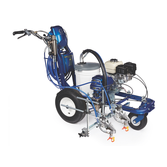
Page 3: Component Identification And Function
Component Identification and Function Model 232651 ENGINE STOP ENGINE SPEED TIP SIZE 8825A Fig. 1 Pressure Control Switch ON/OFF, enables/disables clutch function Pressure Adjusting Knob Controls fluid outlet pressure Air Cleaner* Filters air entering the carburetor Fuel Tank* Uses 86 octane gasoline Muffler* Reduces noise of internal combustion Spark Plug Cable*... - Page 4 Spay Tip Selection Guide LineLazer Tip Selection Guide. Sprayer is supplied with tip LLT319. For additional applications, use the tip selec- tion table as follows: Note: the last three digits (LLT319) of the tip part number identifies the line width and tip orifice (opening) in millimeters. For example: the line width for tip LLT319 is 4 in.
-
Page 5: Maintenance
Maintenance CAUTION WARNING For detailed engine maintenance and specifications, INJECTION HAZARD refer to separate Honda Engines Owner’s Manual, The system pressure must be manually supplied. relieved to prevent the system from starting or spraying accidentally. Fluid under high pressure can be injected through the DAILY: Check engine oil level and fill as necessary. -
Page 6: Troubleshooting
0.2Ω (LL 5900); if not, replace pinion housing. Check control board fuse. If blown, replace with equivalent automotive fuse. Have pressure control checked by authorized Graco dealer. Clutch is worn, damaged, or incorrectly Replace clutch. See page 10. positioned. Pinion assembly is worn or damaged. - Page 7 PROBLEM CAUSE SOLUTION Hose inlet screen (27) is clogged. Clean inlet screen. Pump output is low on upstroke upstroke. Piston ball (25) is not seating. Service piston ball. See manual 308798. Piston packings are worn or damaged. Replace packings. See manual 308798. O-ring (17) in displacement pump is worn or Replace o-ring.
-
Page 8: Bearing Housing And Connecting Rod
Bearing Housing and Connecting Rod NOTE: The item numbers referenced are for the 11. Assemble connecting rod (85) and bearing housing Hi-Boy models. The Lo-Boy models may have different (84). item numbers. Use the Hi-Boy item number and part to find the corresponding Lo-Boy part and item number. -
Page 9: Drive Housing
Drive Housing Removal Installation 1. Liberally apply bearing grease (supplied with replacement gear cluster) to gear cluster (78). and Relieve pressure; page 5. to areas called out by note 3. Use full 0.62 pint (0.29 liter) of grease for LL 3900 and 0.68 pint (0.32 liter) of grease for LL 5900. -
Page 10: Pinion Assembly/Rotor/Field/Shaft/Clutch
Pinion Assembly/Rotor/Field/Shaft/Clutch Removal Fig. 6. If pinion assembly (88a) is attached to clutch 5. Remove four screws (52) and lockwashers (50). housing (92), do 1. through 4. Otherwise, start at 5. Install two screws in threaded holes (E) in rotor. Alternately tighten screws until rotor comes off. - Page 11 Pinion Assembly/Rotor/Field/Shaft/Clutch Installation 1. Fig. 10. Lay two stacks of two dimes on smooth 5. Install four screws (53) and lockwashers (50) with bench surface. torque of 125 in-lb. 6. Fig. 8. Tap pinion shaft (A) in with plastic mallet. 2.
-
Page 12: Clutch Housing
Clutch Housing Removal 1. Fig. 12. Remove four capscrews (98) and lock- 3. Install four capscrews (98) and lockwashers (99) washers (99) which hold clutch housing (92) to and secure clutch housing (92) to engine. engine. 2. Remove cap screw (96), lockwasher (50), and washer (97) from beneath mounting plate (D). -
Page 13: On/Off Switch
On/Off Switch Removal Installation Relieve pressure; page 5. 5. Install new ON/OFF switch (309) so tabs of switch snap into place on inside of pressure control housing. 2. Fig. 15. Remove five screws (307) and cover (322). 6. Connect two wires (A) to ON/OFF switch. 3. -
Page 14: Control Board
Pressure Control Control Board When installing replacement control board, follow instructions with control board to set model type. Relieve pressure; page 5. 1. Fig. 15. Install control board (302) with five 2. Fig. 15. Remove five screws (307) and screws (303). cover (322). -
Page 15: Control Board Diagnostics
Pressure Control Control Board Diagnostics 1. Fig. 15. Remove five screws (307) and 3. Turn ON/OFF switch ON. cover (322). 4. Observe LED operation and reference following 2. Start engine. table: SPRAYER OPERATION INDICATES WHAT TO DO BLINKS Two times Sprayer shuts down and LED contin- Run away pressure. -
Page 16: Displacement Pump
1. Fig. 19. Pull piston rod out 1.5 in. Screw in pump until holes in bearing cross link and piston rod align. Fig. 20 Fig. 21. Fill packing nut with Graco TSL, through one of the slits, until fluid flows onto the top of seal. 1.5 in. Fig. 19... - Page 17 Parts – LineLazer II Models 232651 and 232661 A (Sheet 2) B (Sheet 3) C (Sheet 3) 96 (LL 3900) 97 (LL 5900) D (Sheet 3) 25 Ref 25 Ref E (Sheet 3) 118a F (Sheet 4) 118c 118d 118b Label 118e 118f...
- Page 18 Parts – LineLazer II Models 232651 and 232661 (Cont’d) 74 Ref 106 62 Ref Detail A Sheet 2 of 4...
- Page 19 Parts – LineLazer II Models 232651 and 232661 (Cont’d) 61 Ref 25 Ref 17 Ref 27 Ref 25 Ref Detail B 58 Ref Detail C 37 Ref Detail D 117 Ref 102 Ref Detail E Sheet 3 of 4...
- Page 20 Parts – LineLazer II Models 232651 and 232661 (Cont’d) 118ad 118ae 118aa 118af 118ac 118ab Top View 118am 118an 118ab(Ref) 118ak 118aa(Ref) 118aj 118ah 118ag 118af(Ref) 118ar 118at 118au 118av 118as 3(Ref) 118ap 118aq A–A 8838A Detail F Sheet 4 of 4...
- Page 21 Parts – LineLazer II Models 232651 and 232661 Part No. Description Part No. Description 114631 SCREW, thread forming, hex hd HOLDER, gun PRESSURE CONTROLParts, page 24 100133 WASHER, lock 194071 LABEL, identification 100101 SCREW, cap, hex hd 241444 COVER, abs, painted 186699 BLOCK, mounting, cable 114955...
- Page 22 Parts – LineLazer II Models 232651 and 232661 (Cont’d) Part No. Description Part No. Description BEARING HOUSING 100718 WASHER 240523 LL 3900, Model 232651 107110 LOCKNUT 241015 LL 5900, Model 232661 111235 SCREW, mach, pan hd CONNECTING ROD 114682 SPRING, compression 240008 LL 3900, Model 232651 114802...
- Page 23 Parts – Drive and Pinion Housings 89 (Ref) 50 (Ref) 88 (Ref) 79 (Ref) 87 (Ref) 50 (Ref) 51 (Ref) 79 (Ref) 78 (Ref) 77 (Ref) Only used on LineLazer 3900. Pinion housing 88 includes clutch field and connector. 8715A Ref No.
-
Page 24: Parts - Pressure Control
Parts – Pressure Control NO. PART NO. DESCRIPTION PRESSURE CONTROL (see page 21, item 2 for next higher assembly) 193653 PLA TE, control 241093 BOARD, PC 111839 SCREW, machine, pan hd, 6–32 x 1/2 in. 240776 HARNESS, wiring. 193497 GASKET , control 193652 HOUSING, control box... - Page 25 Parts – Fluid Filter 318f 318e 318d 318b 318c 8716A 318a NO. PART NO. DESCRIPTION 240777 FLUID FILTER 318g (see page 24, item 318 for next higher assembly) 318a . 193651 HOUSING, filter 318h 318b . 104361 O-RING 318m 318c . 186075 SUPPORT, filter 318d .
- Page 26 LineLazer 5900 your sprayer. The drawing shows the best place- European Pail Cover and Holder 240717 ment of these labels for good visibility. Order the labels from your Graco distributor. Flex Gun Repair Kit 235474 Includes needle, gasket, diffuser/seat. Apply other...
-
Page 27: Technical Data
......32 in. (81.3 cm) Graco Phone Number TO PLACE AN ORDER , contact your Graco distributor, or call this number to identify the distributor closest to you: 1–800–690–2894 Toll Free... -
Page 28: Graco Warranty
Graco’s written recommendations. This warranty does not cover, and Graco shall not be liable for general wear and tear , or any malfunction, damage or wear caused by faulty installation, misapplication, abrasion, corrosion, inadequate or improper maintenance, negligence, accident, tampering, or sub- stitution of non–Graco component parts.
Need help?
Do you have a question about the LineLazer II 3900 and is the answer not in the manual?
Questions and answers
what causes my 3900 linelazer to continuously get out of alignment