
Related Manuals for SEW-Eurodrive EMS


Summary of Contents for SEW-Eurodrive EMS
- Page 1 *240-27779165/EN-02/22* Drive Technology \ Drive Automation \ System Integration \ Services Operating manual [27779165/EN] Control technology EMS modular controls Edition 02/2022 240_10030005/EN...
-
Page 3: Table Of Contents
Preferred variant 3: SMGM, STO via PROFIsafe............. Safety functions (only for controls with integrated safety technology)......10.1 Overview ........................10.2 Safety function description ..................10.2.1 STO (safe torque off) ................10.2.2 SLS (safely limited speed) ................ Dimensions .......................... Operating manual [27779165/EN] - EMS modular controls... - Page 4 Installation ........................ 20.2.1 Fastening the control................. 20.2.2 Connections ....................20.2.3 Housing PE connection (control bottom)........... 20.3 Condition after the installation .................. 20.4 First commissioning....................20.5 Switching on sequence .................... 20.6 Operation........................20.7 Decommissioning ..................... Operating manual [27779165/EN] - EMS modular controls...
- Page 5 Transport and storage......................103 23.1 Safety instructions for transport and storage............103 23.2 Transport inspection ....................103 Disassembly and disposal....................104 24.1 Preparation for disassembly ..................104 24.1.1 Disassembly....................104 24.2 Disposal........................105 Index ............................. 107 Operating manual [27779165/EN] - EMS modular controls...
-
Page 6: Document History
Document history Document history Document history Part number Version Issue Description/changes 27779165/EN 1.01 11/2021 First issue 27779165/EN 1.02 02/2022 Part number of this document added; New connector X5: Informa- tion added Operating manual [27779165/EN] - EMS modular controls... -
Page 7: Abbreviations
Communication type: Rail bus, PowerCAN Field bus: PROFINET RS485 Serial interface: RS485 standard SMGM Communication type: SMGM Serial interface: RS422 standard Above sea level Fixed assignment of the contact as a digital input Contact switchable digital input/output Operating manual [27779165/EN] - EMS modular controls... -
Page 8: General
In addition, the local accident prevention regulations and general safety regulations for the use of the system apply. Illustrations serve basic understand- ing and may deviate from the actual version. Operating manual [27779165/EN] - EMS modular controls... -
Page 9: Symbols
NOTICE! Residual voltage from charged capacitors!Severe injury. Do not touch any live product parts or power connections. INFORMATION! Residual voltage from charged capacitors!Severe injury. Do not touch any live product parts or power connections. Operating manual [27779165/EN] - EMS modular controls... - Page 10 Notice text Notice text Notice text Notice text Notice text Notice text Notice text Notice text Notice text Notice text Notice text Notice text Notice text Notice text Notice text No- tice text Notice text Notice text Notice text Notice text Notice text Notice text Notice text Operating manual [27779165/EN] - EMS modular controls...
-
Page 11: Copyright Protection
Customer service SEW-EURODRIVE GmbH & Co KG Ernst-Blickle-Str. 42 Tel: +49 (0) 7251 75-0 Fax: +49 (0) 7251 75- 1970 D - 76646 Bruchsal E-Mail: sew@sew-eurodrive.com Web: www.sew-eurodrive.com Country of origin: Germany Operating manual [27779165/EN] - EMS modular controls... -
Page 12: Warranty
The warranty period and scope are determined by your contractual conditions and the general delivery conditions of SEW-EURODRIVE GmbH & Co KG. The general warranty and delivery conditions can be viewed on our website. www.sew- eurodrive.com... -
Page 13: Safety Instructions
Further task-related safety instructions are contained in the sections about individual life phases. DANGER ⚠ Danger if the safety instructions are not observed Death or serious injuries • Safety regulations must be strictly observed! Operating manual [27779165/EN] - EMS modular controls... -
Page 14: Intended Use & Obvious Misuse
Intended use The controls described in this document are designed exclusively for use in industrial environments in automation systems such as EMS, sorters, push skids and similar ap- plications. The control is approved only for industrial environments in terms of electromagnetic compatibility (EMC). -
Page 15: General Risks
The system must not be changed improperly! WARNING ⚠ Danger from incorrect replacement and dismantling! Accidents and serious injuries • Before starting any dismantling work, safety instructions must be observed. Operating manual [27779165/EN] - EMS modular controls... -
Page 16: Danger From Electrical Energy
It must be ensured that components are not live (switch off the voltage) or, if this is not possible, cover the parts with insulating material. • Live parts must be secured against unauthorized approach. Operating manual [27779165/EN] - EMS modular controls... -
Page 17: Responsibilities Of The Operating Company
The provider must ensure installation and assembly in accordance with EN 60204. • The provider must ensure that all components are disconnected from the power sup- ply in the event of an EMERGENCY STOP. In particular, the power rail installed in parallel. Operating manual [27779165/EN] - EMS modular controls... -
Page 18: Personnel Requirements
In addition, these persons must have read and understood these safety regulations and must adhere to them afterwards. If required, this may have to be confirmed by the customer/user with a signature. Operating manual [27779165/EN] - EMS modular controls... -
Page 19: Personal Protective Equipment
If you have long hair, it must be covered (cap, hat, hairnet or similar). Safety harnesses, face and hearing protection according to DGUV regulation 112-189. Ear protection To protect against serious and permanent hearing damage. Operating manual [27779165/EN] - EMS modular controls... - Page 20 Safety instructions Safety instructions Respiratory protection To protect against serious and permanent diseases of the respiratory tract. Operating manual [27779165/EN] - EMS modular controls...
-
Page 21: Safety Devices
When working on the system, the following accident prevention regulations (UVV) or newly applicable accident prevention regulations - principles of prevention (DGUV reg- ulation 1) must be observed. Operating manual [27779165/EN] - EMS modular controls... -
Page 22: Conduct In Case Of Danger Or Accident
Keep access roads open for rescue vehicles. Behavior in case of accidents • Secure the accident site and call first aiders for first aid. • Alert the ambulance service. • Provide first aid. Operating manual [27779165/EN] - EMS modular controls... -
Page 23: Signage
Always keep all safety, warning and operating instructions in a legible condition. INFORMATION Danger if instructions are not observed Destruction or damage to assemblies • Products may only be used after this document has been completely read and un- derstood! Operating manual [27779165/EN] - EMS modular controls... -
Page 24: Notes About Hazardous Substances
"POP regulation." Information about hazardous substances according to CP65 (or P65) According to the current state of knowledge, the module does not contain any relevant hazardous substances according to the "CP65 regulation." Operating manual [27779165/EN] - EMS modular controls... -
Page 25: Applicable Documents
Communication type: Rail bus (CAN) • Operating instructions for the stationary rail bus module MAXO-RG-BSx • Operating instructions for the mobile rail bus module MAXO-RG-BMS Communication type: SMGM • Operating instructions SMGM (system manual - modules) Operating manual [27779165/EN] - EMS modular controls... -
Page 26: Applied Guidelines, Ordinances And Standards
Adjustable speed electrical drive systems - Part 3: EMC requirements including special test methods DIN EN 61800-5-1:2017-11 Adjustable speed electric power drive systems - Part 5-1: Safety re- quirements - electrical, thermal and energetic requirements Operating manual [27779165/EN] - EMS modular controls... - Page 27 Applied guidelines, ordinances and standards Document No. Document title DIN EN IEC 63000:2019-05 Technical documentation for providing electrical and electronic equip- ment with regard to hazardous substance restrictions *Guidelines [R], delegated guidelines [DR] and implementing decisions [DB] Operating manual [27779165/EN] - EMS modular controls...
-
Page 28: Technical Data
Operation EN 60721-3-3 EN 60721-3-7 Dimensions - housing Without connections L x W x H: 505 x 225 x 405mm With connections L x W x H: 550 x 225 x 405 mm Operating manual [27779165/EN] - EMS modular controls... - Page 29 HAN 3EMV-agg-QB + HAN Q 5/0-F, socket Connection X4: Handheld control connection Number of connections Connection identification Connection type HAN 3A-agg-QB + HAN 12Q-SMC-BE-CRA-PE with QL, socket Missing connections Non-existent connection X4 is provided with a blind cover Operating manual [27779165/EN] - EMS modular controls...
- Page 30 Communication types Rail bus CAN and SMGM Information about PCB see section „16.1 Railbus CAN“ Information about SMGM see section „16.2 SMGM“ Parameterization Interface USB, type C, socket (Behind the IM.1 module cover) Operating manual [27779165/EN] - EMS modular controls...
-
Page 31: System Description
System description Basic system System description The EMS modular control is used on the mobile side of industrial automation systems such as EMS, sorters, skids. The control functions as a compact center for peripherals on the mobile side. Control and query of sensors and actuators, control of various axes (motors) and information transfer to the stationary side for system control (PLC). -
Page 32: Preferred Variant 1: Rail Bus Can + Smgm, Without Safety Function
5: Mobile communication module (here: MAXO-RG-BMS, rail bus CAN)* 6: Remote control for manual operation & maintenance 7: EMS modular control (schematic representation of the functional units) 8: Motors / axles *With this preferred variant, communication via SMGM is also possible. -
Page 33: Preferred Variant 2: Rail Bus Can, Sto Via Power Rail
5: Mobile communication module (here: MAXO-RG-BMS, rail bus CAN) 6: Remote control for manual operation & maintenance 7: EMS modular control (schematic representation of the functional units) 7.1: Safety module for STO function via additional busbar 8: Motors / axles... -
Page 34: Preferred Variant 3: Smgm, Sto Via Profisafe
4: Data matrix positioning system PXV 5: Mobile communication module (here: MAXO-RG-SMS, SMGM) 6: Remote control for manual operation & maintenance 7: EMS modular control (schematic representation of the functional units) 8: Motors / axles Operating manual [27779165/EN] - EMS modular controls... -
Page 35: Safety Functions (Only For Controls With Integrated Safety Technology)
When using the communication type SMGM, the safe torque shutdown is implemented via PROFIsafe. The SLS function is only possible in connection with the STO function. The safely limited speed is implemented by the frequency converter used. Operating manual [27779165/EN] - EMS modular controls... -
Page 36: Safety Function Description
Fig. 10-1 Graphic representation of the STO safety function ITEM Description STO activation STO function activated (1 or HIGH). The axis is de-energized / Axis torque is switched off. Movement at starting speed STO activation time Operating manual [27779165/EN] - EMS modular controls... - Page 37 This depends on the components used and their mass and friction ratios. • Note that other moving parts in the vicinity may have to be switched off separately. Operating manual [27779165/EN] - EMS modular controls...
-
Page 38: Sls (Safely Limited Speed)
Status of the respective axis (1 or HIGH: Axis moves within the pa- rameterized speed limit) SLS - activation time; Monitoring the speed is started Speed above the parameterized speed limit Speed below the parameterized speed limit Parameterized speed limit / Speed threshold Limit Operating manual [27779165/EN] - EMS modular controls... -
Page 39: Dimensions
Dimensions Dimensions Dimensions Fig. 11-1 EMS control unit dimensions, measurements in [mm] Operating manual [27779165/EN] - EMS modular controls... -
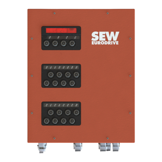
Page 40: Overview
Overview Overview Overview 12.1 Complete overview Fig. 12-1 Overview EMS modular control (figure shows control with three SysBus modules) Connection Description Front with SysBus modules Bottom with feed and power connections Back with heat sink Operating manual [27779165/EN] - EMS modular controls... -
Page 41: Overview: Front
Further information about contacts used and assignment Specific information about the control connections can be found in section “"Connec- tions: Front" ( 47).” You will find the displays in the software description manual. Operating manual [27779165/EN] - EMS modular controls... - Page 42 Further information about contacts used and assignment Specific information about the control connections can be found in section “"Connec- tions: Front" ( 47).” You will find the displays in the software description manual. Operating manual [27779165/EN] - EMS modular controls...
-
Page 43: Overview: Bottom
**If connection X4 is not used, it is provided with a blind cover. Further information about contacts used and assignment Specific information about the connections on the control bottom can be found in section “"Connections: Bottom" ( 42).” Operating manual [27779165/EN] - EMS modular controls... -
Page 44: Connections
Outer conductor L1 Outer conductor L2 Outer conductor L3 Release rail (reference: L3) Release rail, safety relay* Potential equalization *If there is no safety relay in the control, the contact has no function. Operating manual [27779165/EN] - EMS modular controls... -
Page 45: Connection: X2.1
14 (white) Motor phase output W SEW brake connection 15 (blue) TF/TH/KTY+ Motor temperature sen- sor (+) SEW brake connection 13 (red) Motor phase output V TF/TH/KTY- Motor temperature sen- sor (-) PE connection Operating manual [27779165/EN] - EMS modular controls... -
Page 46: Connection: X3
Not connected Connection external braking re- sistor(-) PE connection INFORMATION Danger from signals on unused contacts Malfunctions • Unused or unconnected contacts (n.c.) must remain free. There must be no signal at these contacts. Operating manual [27779165/EN] - EMS modular controls... -
Page 47: Connection: X4
If the handheld control is not plugged in, the safety contacts must be bridged. Other- wise, automatic operation (standard operation) is not possible (control doesn’t move / axis 1 (X2.1 & X2.2) blocked or no voltage output)! Operating manual [27779165/EN] - EMS modular controls... -
Page 48: Connection: X5
Fig. 13-5 Contact assignment connector X5 Specification Description Note Function Communication Interface Direct connection EtherCAT Designation Connection M12, 4pole, D-coded, socket Alignment as shown in figure type Function Description Communication Communication Communication Communication Operating manual [27779165/EN] - EMS modular controls... -
Page 49: Connections: Front
***Depending on the pin configuration, a DIN or DOUT can be set. Depending on the control type, two to a maximum of three SysBus modules are avail- able. SysBus module IM.1 is always required as a master module. Operating manual [27779165/EN] - EMS modular controls... -
Page 50: Sysbus Module: Im.1
SYSCAN interface* M12, 8-pin, A coded, socket For connecting VCS-SMG-SAFE. Information about coding tabs’ alignment / position M12 connection coding tabs are in the "11 o'clock position.” Angled plugs are recommended for the connection. Operating manual [27779165/EN] - EMS modular controls... - Page 51 Fig. 13-8 Contact assignment connections X10 / X11 Specifica- Description Note tion Function Communication interface Fieldbus connection Designation X10 & X11 Connection M12, 4-pin, D-coded, socket Coding tab at position "11 o'clock” type Contact Function Description Communication Communication Communication Communication Operating manual [27779165/EN] - EMS modular controls...
- Page 52 Designation Connection M12, 4-pin, A coded, socket Coding tab at position "11 o'clock” type Contact Function Description Supply voltage IO +24 VDC IM.1-XIN1 DIN 1 Supply ground IO IM.1-XIO1 DIN2 | DOUT 1 Operating manual [27779165/EN] - EMS modular controls...
- Page 53 CAN mass n.c. Not connected n.c. Not connected INFORMATION Danger from signals on unused contacts Malfunctions • Unused or unconnected contacts (n.c.) must remain free. There must be no signal at these contacts. Operating manual [27779165/EN] - EMS modular controls...
-
Page 54: Sysbus Module: Io.1
M12, 4-pin, A coded, socket STO interface 2 M12, 4-pin, A coded, socket Information about coding tabs’ alignment / position M12 connection coding tabs are in the "11 o'clock position.” Angled plugs are recommended for the connection. Operating manual [27779165/EN] - EMS modular controls... - Page 55 M12, 4-pin, A coded, socket Coding tab at position "11 o'clock” type Contact Function Description Supply voltage IO +24 VDC IO.1-XIN 2 DIN 3 Supply ground IO IO.1-XIO 2 DIN 4 | DOUT 2 Operating manual [27779165/EN] - EMS modular controls...
- Page 56 M12, 4-pin, A coded, socket Coding tab at position "11 o'clock” type Contact Function Description Supply voltage IO +24 VDC IO.1-XIN 5 DIN 9 Supply ground IO IO.1-XIO 5 DIN 10 | DOUT 5 Operating manual [27779165/EN] - EMS modular controls...
- Page 57 M12, 4-pin, A coded, socket Coding tab at position "11 o'clock” type Contact Function Description Supply voltage IO +24 VDC IO.1-XIN 6 DIN 11 Supply ground IO IO.1-XIO 6 DIN 12 | DOUT 6 Operating manual [27779165/EN] - EMS modular controls...
- Page 58 Function STO2 interface Designation Connection M12, 4-pin, A coded, socket Coding tab at position "11 o'clock” type Contact Function Description STO2-OUT STO output STO2- STO2 input STO2-GND STO2 mass STO2+ STO2 input + Operating manual [27779165/EN] - EMS modular controls...
-
Page 59: Sysbus Module: Io.2
M12, 5-pin, A coded, socket FU2 safety interface M12, 5-pin, A coded, socket Information about coding tabs’ alignment / position M12 connection coding tabs are in the "11 o'clock position.” Angled plugs are recommended for the connection. Operating manual [27779165/EN] - EMS modular controls... - Page 60 Coding tab at position "11 o'clock” type Contact Function Description Supply voltage +24 VDC b, INC1 Supply ground INC1 Incremental encoder connection Incremental encoder connection Incremental encoder connection Incremental encoder connection n.c. Not connected n.c. Not connected Operating manual [27779165/EN] - EMS modular controls...
- Page 61 Incremental encoder connection n.c. Not connected n.c. Not connected INFORMATION Danger from signals on unused contacts Malfunctions • Unused or unconnected contacts (n.c.) must remain free. There must be no signal at these contacts. Operating manual [27779165/EN] - EMS modular controls...
- Page 62 M12, 5-pin, A coded, socket Coding tab at position "11 o'clock” type Contact Function Internally routed to FU -> FU con- nection F_SS0 FU1: F_SSO F_DI1 FU1: F_DI1 FU1: GND F_DI0 FU1: F_DIO F_SS1 FU1: F_SS1 Operating manual [27779165/EN] - EMS modular controls...
- Page 63 Connection M12, 5-pin, A coded, socket Coding tab at position "11 o'clock” type Contact Function Internally routed to FU F_SS0 FU1: F_SS0 F_DI3 FU1: F_DI3 FU1: GND F_DI2 FU1: F_DI2 F_SS1 FU1: F_SS1 Operating manual [27779165/EN] - EMS modular controls...
- Page 64 F_DO0_M FU1: F_DO0_M F_DO0_P FU1: F_DO0_P FU1: FE INFORMATION Danger from signals on unused contacts Malfunctions • Unused or unconnected contacts (n.c.) must remain free. There must be no signal at these contacts. Operating manual [27779165/EN] - EMS modular controls...
- Page 65 Connection M12, 5-pin, A coded, socket Coding tab at position "11 o'clock” type Contact Function Internally routed to FU F_SS0 FU2: F_SS0 F_DI1 FU2: F_DI1 FU2: GND F_DI0 FU2: F_DI0 F_SS1 FU2: F_SS1 Operating manual [27779165/EN] - EMS modular controls...
- Page 66 SAFE-I2/I3 FU2 interface Designation Connection M12, 5-pin, A coded, socket Coding tab at position "11 o'clock” type Contact Function Description F_SS0 FU2: F_SS0 F_DI3 FU2: F_DI3 FU2: GND F_DI2 FU2: F_DI2 F_SS1 FU2: F_SS1 Operating manual [27779165/EN] - EMS modular controls...
- Page 67 F_DO0_M FU2: F_DO0_M F_DO0_P FU2: F_DO0_P FU2: FE INFORMATION Danger from signals on unused contacts Malfunctions • Unused or unconnected contacts (n.c.) must remain free. There must be no signal at these contacts. Operating manual [27779165/EN] - EMS modular controls...
-
Page 68: Circuits: Power Outputs
Circuits: Power outputs Circuits: Power outputs Circuits: Power outputs The connection of the motor outputs X2.x depends on the respective application of the control. Please refer to the control EPLAN. Operating manual [27779165/EN] - EMS modular controls... -
Page 69: Frequency Converter
The CSL11A option card extends the frequency converter with additional "secure inter- faces." Further information about safety functions can be found in section “"Safety functions (only for controls with integrated safety technology)" ( 33).” Operating manual [27779165/EN] - EMS modular controls... -
Page 70: Communication
Communication Communication Communication The following communication options are available for the EMS modular controls: • Railbus CAN • SMGM Operating manual [27779165/EN] - EMS modular controls... -
Page 71: Railbus Can
4: Wire to the separating segment 5: Conductor line in the busbar system 6: Line with mobile communication consumers 7: Stationary rail bus module (MAXO-RG-BMS) 8: System CAN bus cable 9: EMS modular control Operating manual [27779165/EN] - EMS modular controls... -
Page 72: Interface Description
Axle identification bit 1 Axle 1 stop/speed = 0 Axle 2 stop/speed = 0 Axle 3 stop/speed = 0 Axle 4 stop/speed = 0 Stop conf. Variant bit 0 Stop conf. Variant bit 1 Operating manual [27779165/EN] - EMS modular controls... - Page 73 ON/OFF switch 0 ... 7 Fault number bit 0 - 7 0 ... 7 Speed LOW byte 0 ... 5 Speed bit 8 - 13 Axle identification bit 0 Axle identification bit 1 Operating manual [27779165/EN] - EMS modular controls...
-
Page 74: Smgm
5: EMS modular control 6: HF wires with mobile couplers (2 pieces - for uninterrupted communication) 7: SMGM rail – (2 segment) 8: HF wires with stationary coupler (2 segments are supplied in this configuration) Operating manual [27779165/EN] - EMS modular controls... -
Page 75: Interface Description
1 ... DOUT 3 main flange ON 1 ... DOUT 4 main flange ON Alive bit between EMS and PLC Reserve Reserve Reserve Reserve Reserve Stop conf. Variant bit 0 Stop conf. Variant bit 1 Operating manual [27779165/EN] - EMS modular controls... - Page 76 1 ... DOUT 2 extension flange ON (if available) 1 ... DOUT 3 extension flange ON (if available) 1 ... DOUT 4 extension flange ON (if available) Reserve Reserve Reserve Reserve Reserve Reserve Reserve Reserve Operating manual [27779165/EN] - EMS modular controls...
- Page 77 0 ... 7 Position setting HIGH byte 0 ... forward; 1 ... back Reserve 1 ... Deactivate stop configuration PwrON PosCom request Reserve Reserve Reserve Reserve Reserve Reserve Reserve Reserve Reserve Reserve Reserve Reserve Operating manual [27779165/EN] - EMS modular controls...
- Page 78 Fault number bit 8 (value range 0 - 512) ON/OFF switch 0 ... 7 Fault number bit 0 - 7 0 ... 7 Speed LOW byte 0 ... 5 Speed bit 8 - 13 Alive bit between EMS and PLC Reserve Operating manual [27779165/EN] - EMS modular controls...
- Page 79 DIN 8 extension flange 1 (if available) Reserve Standstill Reserve Position reached Reserve PwrON PosCom request response Reserve 0 ... 7 Reserve 0 ... 7 Speed LOW byte 0 ... 5 Speed bit 8 - 13 Reserve Reserve Operating manual [27779165/EN] - EMS modular controls...
- Page 80 DIN 8 extension flange 2 (if available) Reserve Standstill Reserve Position reached Reserve PwrON PosCom request response Reserve 0 ... 7 Reserve 0 ... 7 Speed LOW byte 0 ... 5 Speed bit 8 - 13 Reserve Reserve Operating manual [27779165/EN] - EMS modular controls...
- Page 81 DIN 8 extension flange 3 (if available) Reserve Standstill Reserve Position reached Reserve PwrON PosCom request response Reserve 0 ... 7 Reserve 0 ... 7 Speed LOW byte 0 ... 5 Speed bit 8 - 13 Reserve Reserve Operating manual [27779165/EN] - EMS modular controls...
- Page 82 Communication Communication PM data (preventive maintenance data) PLC data to EMS modular control - PM data request (CAN-ID = 0x19F) Byte Description 0 ... 7 Index query PM data 0 ... 7 Reserve 0 ... 7 Reserve 0 ... 7 Reserve 0 ...
-
Page 83: Type Code
Type code Type code Type code Operating manual [27779165/EN] - EMS modular controls... -
Page 84: Type Plate
Type plate Type plate Fig. 18-1 Nameplate The nameplate is visibly attached to the EMS modular control and contains the informa- tion shown in the table. The nameplate must be attached to the module in a legible manner over the entire length of its useful life. -
Page 85: Order Overview & Scope
Order overview & scope Order overview & scope Order overview & scope EMS modular controls can be configured in different ways. The following list shows the standard control models. Designation Item No. MAXO-RG-CUS-SPC-00-2-0-1140-1-0-0 25740725 Description Axes: 2; Communication: Railbus CAN + SMGM; Small services: FU1: 1.1 kW | FU2: 4.0 kW;... -
Page 86: Commissioning
The control may only be installed if the information on the control nameplate corre- sponds to the voltage network specifications. Information about the installation location It is intended that control system installation location (EMS vehicle, skids, etc.) contrib- utes to the further minimization of dangers (mechanical/electrical). Operating manual [27779165/EN] - EMS modular controls... -
Page 87: Electrical Installation
During electrical installation, the requirements for an emergency stop device must be observed. This must be planned and executed by the system builder. The E-STOP device function must be regularly checked by the operator. Please note the applicable standards, regulations, etc., as amended. Operating manual [27779165/EN] - EMS modular controls... -
Page 88: Emc
Cut the sensor cables to length or place them directly folded and bound together with cable clips in the cable harness to prevent interspersion and inductions. Ground the EMS vehicle directly via the grounding contact wire: • Connect all moving parts with low resistance to the traverse or main girder. Use cop-... -
Page 89: Operating Modes
• Manual mode In automatic mode the higher-level PLC controls the EMS modular control system’s ac- tions. All sensors are active in this operating mode and are queried. The manual mode is used for repairing, maintaining, servicing and moving the control system in case of a fault. -
Page 90: Installation
*Screw length: L = Te + D safety washer washer carrier material D: Thickness of the component (disc); T: Depth of the component; carrier material: Sus- pension on the vehicle Tightening torque: 6.4 Nm (note the screws’ strength class) Operating manual [27779165/EN] - EMS modular controls... - Page 91 Screw connection must be carried out so the fastening does not loosen during op- eration. • The screw connection must be checked at regular intervals. • Specifications for the screw-in depth must be observed -> recommended screw-in depth. Operating manual [27779165/EN] - EMS modular controls...
-
Page 92: Connections
Installation: M12 connectors (control front, SysBus modules) (Description applies to all M12 connections on the control / SysBus modules) • Plug in M12 plug or M12 blind termination and screw down. • Tightening torque: 0.4 Nm Operating manual [27779165/EN] - EMS modular controls... -
Page 93: Housing Pe Connection (Control Bottom)
Tightening torque: 6.4 Nm (note the screw's strength class) DANGER ⚠ Danger from missing PE connection Death or serious injuries • Both PE connections (from X1 and housing PE connection) must always be connected to the equipotential bonding! Operating manual [27779165/EN] - EMS modular controls... -
Page 94: Condition After The Installation
The specified environmental conditions are observed (see section „"Technical data" ( 26)“). • Specified technical data or information on the control nameplate correspond to the properties of the system in which the control was used. Operating manual [27779165/EN] - EMS modular controls... -
Page 95: First Commissioning
If the handheld control is not plugged in, the safety contacts must be bridged. Other- wise, automatic operation (standard operation) is not possible (control doesn’t move / axis 1 (X2.1 & X2.2) blocked or no voltage output)! Operating manual [27779165/EN] - EMS modular controls... -
Page 96: Switching On Sequence
The control systems acts in accordance with the parameterized specifications (signals at the digital inputs). The current operating status or a status message are shown on the display. A flashing display means a failure is active - see section “"Malfunctions" ( 97)“ Operating manual [27779165/EN] - EMS modular controls... -
Page 97: Operation
During operation, the controls automatically carry out all actions according to the pro- gramming. This means no actions are necessary during automatic operation. In the event of a failure, proceed as described in section „"Malfunctions" ( 97).“ Operating manual [27779165/EN] - EMS modular controls... -
Page 98: Decommissioning
• Secure against being switched on again. • Wait five minutes until the stored charges have completely dissipated. • Disconnect all connections. • Loosen the control fastening and remove it from the bracket. Operating manual [27779165/EN] - EMS modular controls... -
Page 99: Malfunctions
Improper troubleshooting can result in serious personal injury or property damage. • Ensure that there is sufficient clearance before starting work. • Switch off the power supply, check that no voltage is present and protect it from be- ing switched on again. Operating manual [27779165/EN] - EMS modular controls... -
Page 100: Procedure In The Event Of Malfunction
(location, spare part, work carried out, date, inspector's name). System fault elimination may only be carried out by trained, qualified and authorized per- sons. Operating manual [27779165/EN] - EMS modular controls... -
Page 101: Error Messages
Malfunctions Malfunctions 21.3 Error messages You can find the error messages in the software description (manual). Operating manual [27779165/EN] - EMS modular controls... -
Page 102: Return/Repair
Designation of the system in which the assembly is installed • Name of a contact person (for poss. questions) • Module designation and serial number • Error description (which defective pattern was identified? Under which cir- cumstances does the error occur?) Operating manual [27779165/EN] - EMS modular controls... -
Page 103: Maintenance
(location, spare part, work carried out, date, inspector's name). System fault elimination may only be carried out by trained, qualified and authorized per- sons. Date Name Maintenance and ser- Instructions are Signature vicing work given by Operating manual [27779165/EN] - EMS modular controls... -
Page 104: Safety Information About Repairs
Danger - stumbling due to protruding components Injuries • When entering the work and danger area, pay attention to steps and depressions in the floor. There must be no loose objects in the work area. Operating manual [27779165/EN] - EMS modular controls... -
Page 105: Transport And Storage
Obvious transport damage must be reported to the transport company immediately or acceptance with reservation. It is at recipient's discretion to refuse delivery accep- tance in the event of transport damage. • All defects must be documented and reported to the manufacturer. Operating manual [27779165/EN] - EMS modular controls... -
Page 106: Disassembly And Disposal
Before starting any dismantling work, the safety instructions must be observed. CAUTION ⚠ All accessories must be checked for wear! Only parts in perfect condition may be used again. • Only original SEW spare parts may be used. Operating manual [27779165/EN] - EMS modular controls... -
Page 107: Disposal
The provider, as a professional user of the products, is responsible for the proper disposal or recycling of the (old) products. • Contact a recovery, recycling or disposal company that specializes in electronic waste. Operating manual [27779165/EN] - EMS modular controls... - Page 108 The product may not be disposed of in unsorted waste, but must be brought to sep- arate collection points for disposal / recovery (recycling). • The black bar under the symbol indicates the product was placed on the market after August 13, 2005. Operating manual [27779165/EN] - EMS modular controls...
-
Page 109: Index
EMC ..............86 First commissioning ........... 93 Grounding ............85 Information about the instructions ......6 Operating modes ..........87 Repair .............. 100 safety aspects ............ 11 Switch-on sequence........... 94 Symbol explanations ..........7 Operating manual [27779165/EN] - EMS modular controls...
Need help?
Do you have a question about the EMS and is the answer not in the manual?
Questions and answers