
Related Manuals for GEM eSyStep 639 S0 Series


Summary of Contents for GEM eSyStep 639 S0 Series
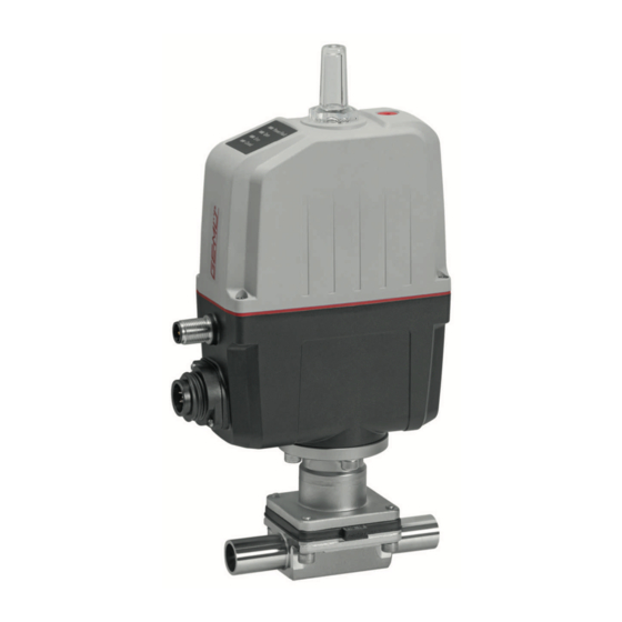
- Page 1 GEMÜ 639 eSyStep Positioner (Code S0) Motorized diaphragm valve Operating instructions TYPE EL CLASS I AUGUST 2021 further information webcode: GW-639...
- Page 2 All rights including copyrights or industrial property rights are expressly reserved. Keep the document for future reference. © GEMÜ Gebr. Müller Apparatebau GmbH & Co. KG 09.05.2022 GEMÜ 639 eSyStep 2 / 72 www.gemu-group.com Positioner (Code S0)
-
Page 3: Table Of Contents
LED symbols ..........Definition of terms ........Warning notes ..........2 Safety information ..........3 Product description ..........4 GEMÜ CONEXO ............ 5 Correct use ............6 Order data ............7 Technical data ............. Behaviour in the event of an error .... -
Page 4: General Information
1.4 Definition of terms Corrosive chemicals Working medium The medium that flows through the GEMÜ product. Diaphragm size Uniform seat size of GEMÜ diaphragm valves for different Hot plant components! nominal sizes. 1.5 Warning notes Wherever possible, warning notes are organised according to... -
Page 5: Safety Information
Diaphragm CR, EPDM, FKM, NBR, turer first. PTFE/EPDM (one-piece), PTFE/EPDM (two-piece) In cases of uncertainty: CONEXO diaphragm 15. Consult the nearest GEMÜ sales office. RFID chip (see Conexo informa- tion) www.gemu-group.com 5 / 72 GEMÜ 639 eSyStep Positioner (Code S0) - Page 6 (on) flashes 3.3 Description The GEMÜ 639 is a motorized 2/2-way diaphragm valve. The eSyStep electric actuator is available as ON/OFF or with integ- rated positioner. An integral optical and electrical position in- dicator is standard. The self-locking actuator holds its posi- tion in a stable manner when idle and in the event of power supply failure.
-
Page 7: Gemü Conexo
RFID chip is used for traceability in the production process and quality assurance. Expansion to include the CONEXO functionality at a later date must be coordinated with GEMÜ. Order with CONEXO GEMÜ CONEXO must be ordered separately with the ordering option "CONEXO"... -
Page 8: Order Data
Threaded socket DIN ISO 228 1.4408, investment casting Threaded socket NPT 1.4408, PFA lined Threaded spigot DIN 11851 1.4435, investment casting Cone spigot and union nut DIN 11851 Forged material 1.4435 (F316L), forged body GEMÜ 639 eSyStep 8 / 72 www.gemu-group.com Positioner (Code S0) - Page 9 Code Description 1 Type Diaphragm valve, electrically operated, eSyStep 2 DN DN 15 3 Body configuration 2/2-way body 4 Connection type Spigot ISO 1127/EN 10357 series C/DIN 11866 series B www.gemu-group.com 9 / 72 GEMÜ 639 eSyStep Positioner (Code S0)
- Page 10 Ra ≤ 0.8 µm (30 µin.) for media wetted surfaces, in accordance with DIN 11866 HE3, electropolished internal/external 10 Actuator version Actuator size 0 11 Special version Without 12 CONEXO Integrated RFID chip for electronic identification and traceability GEMÜ 639 eSyStep 10 / 72 www.gemu-group.com Positioner (Code S0)
-
Page 11: Technical Data
PTFE diaphragms exposed to high temperature fluctuations. The maintenance cycles must be adapted accordingly. GEMÜ 555 and 505 globe valves are particularly suitable for use in the area of steam generation and distribution. The following valve arrangement for interfaces between steam pipes and process pipes has proven itself over time: A globe valve for shutting off steam pipes and a diaphragm valve as an interface to the process pipes. - Page 12 Therefore the Kv values may exceed the tolerance limits of the stand- ard. The Kv value curve (Kv value dependent on valve stroke) can vary depending on the diaphragm material and dur- ation of use. GEMÜ 639 eSyStep 12 / 72 www.gemu-group.com Positioner (Code S0)
- Page 13 DIN EN 61000-6-4 (07/2011) DIN EN 61326-1 (industry) (07/2013) Interference emission class: Class A Interference emission group: Group 1 Interference resistance DIN EN 61000-6-2 (03/2006) DIN EN 61326-1 (industry) (07/2013) www.gemu-group.com 13 / 72 GEMÜ 639 eSyStep Positioner (Code S0)
- Page 14 MG = diaphragm size, weight in kg Mechanical environ- Class 4M8 acc. to EN 60721-3-4:1998 mental conditions: Vibration: 5g acc. to IEC 60068-2-6 Test Fc Shock: 25g acc. to 60068-2-27 Test Ea GEMÜ 639 eSyStep 14 / 72 www.gemu-group.com Positioner (Code S0)
- Page 15 ▶ With reduced forces, higher duty cycles and/or higher ambient temperatures are possible. At higher force settings the duty cycle and/or ambient temperature is reduced. ▶ IO-Link: Index 0x90 - Subindex 2 - Force www.gemu-group.com 15 / 72 GEMÜ 639 eSyStep Positioner (Code S0)
- Page 16 0/4 - 20 mA; 0 - 10 V (function selectable via IO-Link) Output type: active Accuracy: ≤ ±1% of full flow Temperature drift: ≤ ±0.1% / 10°K Load resistor: ≤ 750 kΩ Resolution: 12 bit Short-circuit proof: GEMÜ 639 eSyStep 16 / 72 www.gemu-group.com Positioner (Code S0)
-
Page 17: Behaviour In The Event Of An Error
Notes: Moving to the error position is only possible with full power supply. This behaviour is not a safety position. The valve must be operated with a GEMÜ 1571 emergency power supply module (see accessories) to ensure the function in case of voltage loss. -
Page 18: Dimensions
124.0 32.5 70.0 82.0 150.0 32 - 40 304.0 122.0 32.5 70.0 82.0 150.0 Dimensions in mm MG = diaphragm size * CT = A + H1 (see body dimensions) GEMÜ 639 eSyStep 18 / 72 www.gemu-group.com Positioner (Code S0) - Page 19 1/2" 25.0 19.0 21.3 12.5 108.0 1/2" 25.0 19.0 21.3 13.0 120.0 3/4" 25.0 23.0 26.9 16.0 120.0 1" 25.0 29.0 33.7 19.0 120.0 1¼" 25.0 35.0 42.4 24.0 153.0 www.gemu-group.com 19 / 72 GEMÜ 639 eSyStep Positioner (Code S0)
- Page 20 Code 60: Spigot ISO 1127/EN 10357 series C/DIN 11866 series B 2) Valve body material Code 40: 1.4435 (F316L), forged body Code 42: 1.4435 (BN2), forged body, Δ Fe < 0.5% Code F4: 1.4539, forged body GEMÜ 639 eSyStep 20 / 72 www.gemu-group.com Positioner (Code S0)
- Page 21 2) Valve body material Code 40: 1.4435 (F316L), forged body Code 42: 1.4435 (BN2), forged body, Δ Fe < 0.5% Code C3: 1.4435, investment casting Code F4: 1.4539, forged body www.gemu-group.com 21 / 72 GEMÜ 639 eSyStep Positioner (Code S0)
- Page 22 2) Valve body material Code 40: 1.4435 (F316L), forged body Code 42: 1.4435 (BN2), forged body, Δ Fe < 0.5% Code C3: 1.4435, investment casting Code F4: 1.4539, forged body GEMÜ 639 eSyStep 22 / 72 www.gemu-group.com Positioner (Code S0)
- Page 23 = number of flats 1) Connection type Code 1: Threaded socket DIN ISO 228 2) Valve body material Code 12: CW614N, CW617N (brass) Code 37: 1.4408, investment casting Code 90: EN-GJS-400-18-LT (GGG 40.3) www.gemu-group.com 23 / 72 GEMÜ 639 eSyStep Positioner (Code S0)
- Page 24 MG = diaphragm size n = number of flats 1) Connection type Code 31: Threaded socket NPT 2) Valve body material Code 37: 1.4408, investment casting Code 90: EN-GJS-400-18-LT (GGG 40.3) GEMÜ 639 eSyStep 24 / 72 www.gemu-group.com Positioner (Code S0)
- Page 25 MG = diaphragm size 1) Connection type Code 6: Threaded spigot DIN 11851 2) Valve body material Code 40: 1.4435 (F316L), forged body Code 42: 1.4435 (BN2), forged body, Δ Fe < 0.5% www.gemu-group.com 25 / 72 GEMÜ 639 eSyStep Positioner (Code S0)
- Page 26 1) Connection type Code 6K: Cone spigot and union nut DIN 11851 2) Valve body material Code 40: 1.4435 (F316L), forged body Code 42: 1.4435 (BN2), forged body, Δ Fe < 0.5% GEMÜ 639 eSyStep 26 / 72 www.gemu-group.com Positioner (Code S0)
- Page 27 Code 39: 1.4408, PFA lined Code 40: 1.4435 (F316L), forged body Code 42: 1.4435 (BN2), forged body, Δ Fe < 0.5% Code 83: EN-GJS-400-18-LT (GGG 40.3), hard rubber lined Code C3: 1.4435, investment casting www.gemu-group.com 27 / 72 GEMÜ 639 eSyStep Positioner (Code S0)
- Page 28 Code 39: 1.4408, PFA lined Code 40: 1.4435 (F316L), forged body Code 42: 1.4435 (BN2), forged body, Δ Fe < 0.5% Code 83: EN-GJS-400-18-LT (GGG 40.3), hard rubber lined Code C3: 1.4435, investment casting GEMÜ 639 eSyStep 28 / 72 www.gemu-group.com Positioner (Code S0)
- Page 29 Code 8T: Clamp DIN 32676 series C, face-to-face dimension FTF EN 558 series 7, length only for body configuration D 2) Valve body material Code 40: 1.4435 (F316L), forged body Code 42: 1.4435 (BN2), forged body, Δ Fe < 0.5% Code F4: 1.4539, forged body www.gemu-group.com 29 / 72 GEMÜ 639 eSyStep Positioner (Code S0)
-
Page 30: Manufacturer's Information
Use appropriate, functional and safe tools. 4. Do not store solvents, chemicals, acids, fuels or similar ● fluids in the same room as GEMÜ products and their spare 1. Ensure the product is suitable for the relevant application. parts. 2. Check the technical data of the product and the materials. -
Page 31: Installation With Clamp Connections
4. Re-attach or reactivate all safety and protective devices. 7. Re-attach or reactivate all safety and protective devices. 8. Flush the system. 10.5 Installation with threaded sockets Fig. 3: Threaded socket www.gemu-group.com 31 / 72 GEMÜ 639 eSyStep Positioner (Code S0) -
Page 32: Electrical Connection
Digital input/output Digital output, IO-Link n.c. 11.2.2 Connection X2 (only for positioner design) 5-pin M12 plug, A-coded Signal name I+/U+, set value input I-/U-, set value input I+/U+, actual value output GEMÜ 639 eSyStep 32 / 72 www.gemu-group.com Positioner (Code S0) - Page 33 Safe/On tialization Digital input/output Open/Closed/Error/Error and Error Error warning/Initialization Digital output Open/Closed/Error/Error and Closed Closed warning Analogue input 4–20 mA/0–20 mA/0–10 V 4–20 mA 4–20 mA Analogue output 4–20 mA/0–20 mA/0–10 V 4–20 mA 4–20 mA www.gemu-group.com 33 / 72 GEMÜ 639 eSyStep Positioner (Code S0)
- Page 34 Adjustable 0-20mA / 0-10V Analogue input 5-pin M12 plug Actual value (Y)+ A-coded Default setting 4 -20mA Actual value (Y)- Adjustable 0-20mA / 0-10V Switch Consumer Signal direction Power supply GEMÜ 639 eSyStep 34 / 72 www.gemu-group.com Positioner (Code S0)
-
Page 35: Specific Data Io-Link (Pin 6)
12.1 Operation on IO-Link 12.1.1 Operation on PLC as a 24 V device The motorized actuator GEMÜ eSyStep can be operated directly in a PLC control unit without limitations. Technical data of the product and of PLC must be complied with. - Page 36 During IO-Link operation, pin 6 cannot be evaluated by the PLC control unit as an output signal. Item Name eSyStep PLC with supply voltage USB IO-Link Master USB interface Mains plug – laptop GEMÜ 639 eSyStep 36 / 72 www.gemu-group.com Positioner (Code S0)
- Page 37 ● Connect pin 4 (CQ) IO-Link master with pin 6 of the product. Do not connect (pin 3) L- IO-Link master. (L-) Item Name eSyStep B1 and B2 Supply voltages USB IO-Link Master www.gemu-group.com 37 / 72 GEMÜ 639 eSyStep Positioner (Code S0)
-
Page 38: Process Data
1 → Process valve in Closed position Operating mode 0 → Normal operation 1 → Initialization mode Valve position analog 8 … 23 Position of the valve in the range 0 … 1000 GEMÜ 639 eSyStep 38 / 72 www.gemu-group.com Positioner (Code S0) -
Page 39: Parameter Overview
Read out product ID "eSyStep Posi- tioner" 0x15 Serial number Read out serial "XXXXXXXX/YYYY" number 0x16 Hardware revision Read out hardware "Rev. XX/XX" version 0x17 Firmware revision Read out software "V X.X.X.X." version www.gemu-group.com 39 / 72 GEMÜ 639 eSyStep Positioner (Code S0) - Page 40 Input / output 1 Configure logical di- 0 → Active high gital input/output 1 → Active low Output 2 Configure logical di- 0 → Active high gital output 1 → Active low GEMÜ 639 eSyStep 40 / 72 www.gemu-group.com Positioner (Code S0)
- Page 41 Operating time 0 to 255 OPEN (0 to 25.5s) Close Operating time 0 to 255 CLOSE (0 to 25.5s) 0x90 Drive sets Force Force, dependent on 1 … 6 valve used www.gemu-group.com 41 / 72 GEMÜ 639 eSyStep Positioner (Code S0)
- Page 42 1 → 4 to 20 mA 2 → 0 to 10 V Min. Determine minimum 0 to Max signal output (0.0% to Max) Determine max- 1000 Min to 1000 imum signal output (Min to 100%) GEMÜ 639 eSyStep 42 / 72 www.gemu-group.com Positioner (Code S0)
-
Page 43: Parameter
1 byte Data storage index Data Storage Cmd UIntegerT8 1 byte State Property UIntegerT8 4 bytes Data Storage Size UIntegerT32 4 bytes Parameter Check- UIntegerT32 41 bytes Index List OctetStringT www.gemu-group.com 43 / 72 GEMÜ 639 eSyStep Positioner (Code S0) - Page 44 ArrayT 0x8000 Characteristics 0x8002 0x8003 0x8100 Description of parameter values Index name Parameter Values Description Profile Characteristics 0x8000 Device identification objects 0x8002 Process data mapping 0x8003 Diagnostics 0x8100 External identification GEMÜ 639 eSyStep 44 / 72 www.gemu-group.com Positioner (Code S0)
- Page 45 The device name can be read out in ASCII format with the Product name parameter. Index Sub- Off- Access Length Index name Parameter Type Values Index Rights 0x12 18 byte Product name StringT "eSyStep Positioner" www.gemu-group.com 45 / 72 GEMÜ 639 eSyStep Positioner (Code S0)
- Page 46 A text with 32 characters can be stored in the device with the Application specific tag parameter. For example, installation location, function, installation date, etc. Index Sub- Off- Access Length Index name Parameter Type Values Index Rights 0x18 32 bytes Application StringT „**************** " specific tag GEMÜ 639 eSyStep 46 / 72 www.gemu-group.com Positioner (Code S0)
- Page 47 Values Index Rights 0x25 39 byte Detailed Device ArrayT See chapter 12.5 Events Status Description of parameter values Index name Parameter Values Description Detailed Device Status See chapter 12.5 Events www.gemu-group.com 47 / 72 GEMÜ 639 eSyStep Positioner (Code S0)
- Page 48 The functions of the digital inputs can be configured with the Function digital inputs parameter. Index Sub- Off- Access Length Index name Parameter Type Default Values Rights 0x4B 3 bits Function digital in- Input 1 uint:8 puts 3 bits Input 2 uint:8 GEMÜ 639 eSyStep 48 / 72 www.gemu-group.com Positioner (Code S0)
- Page 49 The safety position is defined by the parameter Error Action (index 0x4F (see "Error Action'"). (Init) Input can be used as an initialization input. www.gemu-group.com 49 / 72 GEMÜ 639 eSyStep Positioner (Code S0)
- Page 50 (Output Error & Warning) Output error and warnings. (Input Init) Configure input/output as initialization input. Type in- / output (Push-Pull) Configure output as Push-Pull. (NPN) Configure output as NPN. (PNP) Configure output as PNP. GEMÜ 639 eSyStep 50 / 72 www.gemu-group.com Positioner (Code S0)
- Page 51 (Active high) Input 2 not inversed. (Active low) Input 2 inversed. Input / output 1 (Active high) Input/output not inversed. (Active low) Input/output inversed. Output 2 (Active high) Output not inversed. (Active low) Output inversed. www.gemu-group.com 51 / 72 GEMÜ 639 eSyStep Positioner (Code S0)
- Page 52 (Open) Actuator moves to the OPEN position in case of an error. (Close) Actuator moves to the CLOSED position in case of an error. Error time 1 … 1000 Determine delay time between error detection and error mes- sage. GEMÜ 639 eSyStep 52 / 72 www.gemu-group.com Positioner (Code S0)
- Page 53 Operating mode for OPEN/CLOSE control activated. IO-Link process data (Disabled) Use of IO-Link process data (see “Process data“, page 38) is deactivated. (Enabled) Use of IO-Link process data (see “Process data“, page 38) is activated. www.gemu-group.com 53 / 72 GEMÜ 639 eSyStep Positioner (Code S0)
- Page 54 Open 0 … 4092 Analog value valve position OPEN Close 0 … 4092 Analog value valve position CLOSED Stroke 0 … 4092 Analog value stroke (difference between OPEN and CLOSED). GEMÜ 639 eSyStep 54 / 72 www.gemu-group.com Positioner (Code S0)
- Page 55 Read out current analog value of the supply voltage. Temperature 0 … 4095 Read out current analog value of the temperature sensor. Set value (W) 0 … 4095 Read out current analog value of the set value. www.gemu-group.com 55 / 72 GEMÜ 639 eSyStep Positioner (Code S0)
- Page 56 1 … 6 Set the force during initialization. Preset at the factory de- pending on the valve type. Force settings Actuator size Setting parameter Force AG0 and AG1 Minimum force Maximum force GEMÜ 639 eSyStep 56 / 72 www.gemu-group.com Positioner (Code S0)
- Page 57 800 … 1000 Set the sealing function valve position OPEN. (80.0 … 100.0 %) Close tight 0 … 200 Set the sealing function valve position CLOSED. (0 … 20.0 %) www.gemu-group.com 57 / 72 GEMÜ 639 eSyStep Positioner (Code S0)
- Page 58 Set the stroke limiter of the control range in valve position (Min Pos to OPEN. 100.0%) Min pos 0 to Max Pos Set the stroke limiter of the control range in valve position (0.0% to Max CLOSED. Pos) GEMÜ 639 eSyStep 58 / 72 www.gemu-group.com Positioner (Code S0)
- Page 59 U max 100 to 110 Determine maximum value of the voltage input. If the set (10.0 to 11.0 V) value is exceeded, the message "Set value too high" is is- sued. www.gemu-group.com 59 / 72 GEMÜ 639 eSyStep Positioner (Code S0)
-
Page 60: Events
Event Description Possible cause Troubleshooting Device Hardware Fault The event occurs when a hard- Fault in valve position detec- Contact GEMÜ Support 0x5000 ware fault is detected. tion. Parameter can no longer be read when switching the device on. Motor Unable To Move... - Page 61 Error when replacing a dia- ection. phragm (stroke of the valve in incorrect area). Actuator has been fitted on the valve incorrectly (stroke of the valve in the incorrect area). www.gemu-group.com 61 / 72 GEMÜ 639 eSyStep Positioner (Code S0)
-
Page 62: Operation
ð OPEN and CLOSED LEDs flash alternately. 2. Valve automatically moves into the OPEN position. 3. Valve automatically moves into the CLOSED position. 4. Initialization mode is automatically ended. 5. The end positions are set. GEMÜ 639 eSyStep 62 / 72 www.gemu-group.com Positioner (Code S0) -
Page 63: Inspection And Maintenance
5. Depressurize the plant or plant component. 14.3 Removing the diaphragm 6. Actuate GEMÜ products which are always in the same po- 1. Remove actuator A (see chapter "Removing the actuator"). sition four times a year. 2. Unscrew the diaphragm. - Page 64 7. When definitive resistance is felt, turn back the diaphragm until its bolt holes are in correct alignment with the bolt the guides. holes of the actuator. 8. Align the weir of compressor and diaphragm in parallel. GEMÜ 639 eSyStep 64 / 72 www.gemu-group.com Positioner (Code S0)
- Page 65 7. Ensure even compression of the diaphragm (approx. 10 to 15%). ð Even compression is detected by an even outer bulge. 8. With the valve fully assembled, check the function and tightness. 9. Carry out initialisation. www.gemu-group.com 65 / 72 GEMÜ 639 eSyStep Positioner (Code S0)
-
Page 66: Troubleshooting
Emergency power operation, CLOSED position Emergency power operation, position unknown Set value too small Set value too high Maintenance required, OPEN position Maintenance required, CLOSED position Maintenance required, position unknown GEMÜ 639 eSyStep 66 / 72 www.gemu-group.com Positioner (Code S0) - Page 67 Valve body / actuator damaged Replace valve body/actuator Body of the GEMÜ product is leaking Body of the GEMÜ product is faulty or Check the body of the GEMÜ product for corroded potential damage, replace body if neces-...
-
Page 68: Removal From Piping
3. Disassemble the product. Observe warning notes and goods can be processed only when this note is completed. If safety information. no return delivery note is included with the product, GEMÜ cannot process credits or repair work but will dispose of the 17 Disposal goods at the operator's expense. -
Page 69: Declaration Of Incorporation According To 2006/42/Ec (Machinery Directive)
19 Declaration of Incorporation according to 2006/42/EC (Machinery Directive) Declaration of Incorporation according to the EC Machinery Directive 2006/42/EC, Annex II, 1.B for partly completed machinery GEMÜ Gebr. Müller Apparatebau GmbH & Co. KG Fritz-Müller-Straße 6-8 74653 Ingelfingen-Criesbach, Germany declare that the following product Make: GEMÜ... -
Page 70: Declaration Of Conformity According To 2014/68/Eu (Pressure Equipment Directive)
EN 1983, AD 2000 Note for products with a nominal size ≤ DN 25: The products are developed and produced according to GEMÜ process instructions and quality standards which comply with the requirements of ISO 9001 and ISO 14001. According to Article 4, Paragraph 3 of the Pressure Equipment Directive 2014/68/EU these products must not be identified by a CE-label. -
Page 71: Declaration Of Conformity According To 2014/30/Eu (Emc Directive)
21 Declaration of conformity according to 2014/30/EU (EMC Directive) EU Declaration of Conformity in accordance with 2014/30/EU (EMC Directive) GEMÜ Gebr. Müller Apparatebau GmbH & Co. KG Fritz-Müller-Straße 6-8 74653 Ingelfingen-Criesbach, Germany declare that the product listed below complies with the safety requirements of the EMC Directive 2014/30/EU. - Page 72 GEMÜ Gebr. Müller Apparatebau GmbH & Co. KG Fritz-Müller-Straße 6-8, 74653 Ingelfingen-Criesbach, Germany Subject to alteration Phone +49 (0) 7940 1230 · info@gemue.de www.gemu-group.com 05.2022 | 88668314...
Need help?
Do you have a question about the eSyStep 639 S0 Series and is the answer not in the manual?
Questions and answers