Chapters
Table of Contents

Related Manuals for GEM 638


Summary of Contents for GEM 638
- Page 1 Tiefsitzmembranventil Metall, DN 25 - 150 Full Bore Diaphragm Valve Metal, DN 25 - 150 ORIGINAL EINBAU- UND MONTAGEANLEITUNG INSTALLATION, OPERATING AND MAINTENANCE INSTRUCTIONS...
-
Page 2: Table Of Contents
Allgemeine Sicherheitshinweise 2 Sachgerechter Transport und Lagerung Hinweise für Service- Installation und Inbetriebnahme durch und Bedienpersonal eingewiesenes Fachpersonal Warnhinweise Bedienung gemäß dieser Einbau- und Verwendete Symbole Montageanleitung Begriff sbestimmungen Ordnungsgemäße Instandhaltung Vorgesehener Einsatzbereich Technische Daten Korrekte Montage, Bedienung und Wartung Bestelldaten oder Reparatur gewährleisten einen... -
Page 3: Hinweise Für Service
Möglicherweise gefährliche Situation! dürfen nicht ohne vorherige Abstimmung ® Bei Nichtbeachtung drohen mit dem Hersteller durchgeführt werden. Sachschäden. GEFAHR Sicherheitsdatenblätter bzw. die für die verwendeten Medien geltenden Sicherheitsvorschriften unbedingt beachten! Bei Unklarheiten: Bei nächstgelegener GEMÜ- Verkaufsniederlassung nachfragen. 3 / 36... -
Page 4: Verwendete Symbole
Verwendete Symbole Vorgesehener Einsatzbereich Das Tiefsitzmembranventil Gefahr durch heiße Oberfl ächen! GEMÜ 638 ist für den Einsatz in Rohrleitungen konzipiert. Es steuert ein durchfl ießendes Medium mit Motor- bzw. Gefahr durch ätzende Stoff e! Steuerungseinheiten der Firma AUMA. Das Ventil darf nur gemäß den... -
Page 5: Technische Daten
Ventil ermittelt. Für die angegebenen Werte ist die Dichtheit am Ventilsitz und nach außen gewährleistet. Angaben zu beidseitig anstehenden Betriebsdrücken und für Reinstmedien auf Anfrage. Kv-Werte ermittelt gemäß DIN EN 60534, Eingangsdruck 5 bar, Δp 1 bar, Ventilkörperwerkstoff Grauguss EN-GJL-250 mit Anschluss Flansch EN 1092 Baulänge EN 558 Reihe 7 und Weichelastomermembrane. -
Page 6: Bestelldaten
Code Flansch ANSI Class 125 FF, Baulänge EN 558, Reihe 7, ISO 5752, basic series 7 Übersicht der verfügbaren Ventilkörper für GEMÜ 638 siehe Datenblatt Seite 6 EPDM Bestelldaten: Die Bestellung muss 2 Positionen beinhalten! Pos. 1 Ventil mit Adapter und passender AUMA Lineareinheit Pos. -
Page 7: Lagerung
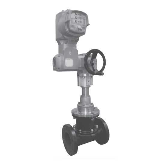
Montage ist nicht im Lieferumfang enthalten. Passendes, funktionsfähiges und sicheres Werkzeug benutzen. Funktionsbeschreibung Das motorgesteuerte 2/2-Wege-Ventil GEMÜ 638 ist ein Tiefsitzmembranventil mit Motor- bzw. Steuerungseinheiten der Firma AUMA. Ventilkörper und Membrane sind gemäß Datenblatt in verschiedenen Ausführungen erhältlich. Geräteaufbau Ventilkörper Membrane Zwischenstück... -
Page 8: Montage Und Bedienung
10 Montage und Bedienung Montagearbeiten nur durch geschultes Fachpersonal. Vor Einbau: Geeignete Schutzausrüstung gemäß Eignung Ventilkörper- und den Regelungen des Anlagenbetreibers Membranwerkstoff entsprechend berücksichtigen. Betriebsmedium prüfen. Siehe Kapitel 5 "Technische Daten". Installationsort: VORSICHT 10.1 Montage des Ventils Ventil äußerlich nicht stark beanspruchen. -
Page 9: Bedienung
11 Montage / Demontage Montage bei Flanschanschluss: von Ersatzteilen 1. Auf saubere und unbeschädigte Dichtfl ächen der Anschlussfl ansche GEFAHR achten. 2. Flansche vor Verschrauben sorgfältig Stromschlag durch gefährliche ausrichten. Spannung! 3. Dichtungen gut zentrieren. Ein elektrischer Schlag kann zu ®... -
Page 10: Demontage Ventil (Zwischenstück Vom Körper Lösen)
3. Alle Teile auf Beschädigungen prüfen. Falsch montierte Membrane führt 4. Beschädigte Teile austauschen (nur ggf. zu Undichtheit des Ventils / Originalteile von GEMÜ verwenden). Mediumsaustritt. Ist dies der Fall dann Membrane demontieren, komplettes Ventil und Membrane überprüfen und erneut nach obiger Anleitung montieren. -
Page 11: Montage Der Tiefsitzmembrane
11.3.2 Montage der DN 25 - 40: Tiefsitzmembrane Druckstück und Antriebsflansch von unten gesehen: DN 50 - 65: Wichtig: Druckstück und Antriebsflansch von unten Für Ventil passende Membrane gesehen: einbauen (geeignet für Medium, Mediumkonzentration, Temperatur und Druck). 1. Vor Montage der neuen Membrane Antrieb demontieren wie unter Kapitel 11.2 "Demontage Membrane"... -
Page 12: Prüfung Der Endlagen Und Drehmomente
erkennbar an gleichmäßiger Vorgehensweise: Außenwölbung). • Beide Sicherungsschrauben lösen. 6. Ventil an Stromnetz anschließen. • Skalenscheiben durch Verdrehen 7. Komplett montiertes Ventil auf Dichtheit auf das erforderliche Drehmoment prüfen. einstellen. • Beide Sicherungsschrauben Wichtig: festziehen. Wartung und Service: Membranen setzen sich im Laufe der Zeit. -
Page 13: Inspektion Und Wartung
Rücksendung nur mit vollständig GEMÜ keinerlei Haftung. ausgefüllter Rücksendeerklärung. Nehmen Sie im Zweifelsfall vor Ansonsten erfolgt keine Inbetriebnahme Kontakt mit GEMÜ auf. Gutschrift bzw. keine 1. Geeignete Schutzausrüstung gemäß Erledigung der Reparatur den Regelungen des Anlagenbetreibers sondern eine kostenpflichtige Entsorgung. -
Page 14: Hinweise
17 Hinweise Im Zweifelsfall oder bei Missverständnissen ist die deutsche Version des Dokuments Hinweis zur ausschlaggebend! Mitarbeiterschulung: Zur Mitarbeiterschulung nehmen Sie bitte über die Adresse auf der letzten Seite Kontakt auf. 18 Fehlersuche / Störungsbehebung Fehler Möglicher Grund Fehlerbehebung Betriebsmedium Membrane auf Beschädigungen prüfen, ggf. -
Page 15: Schnittbild Und Ersatzteile
19 Schnittbild und Ersatzteile Pos. Benennung Bestellbezeichnung Ventilkörper K655… Tiefsitzmembrane 655…M… Schraube / Stiftschraube 655...S30... Scheibe (auf Anfrage) Mutter Antrieb AUMA... Steuerung (AUMA) Lineareinheit (AUMA) * Durch geeignete Konstruktion an der Gewindebohrung G (M10 bzw. M12 je nach Nennweite) die komplette Last des Antriebs abstützen. - Page 16 Die Produkte werden entwickelt und produziert nach GEMÜ eigenen Verfahrensanweisungen und Qualitätsstandards, welche die Forderungen der ISO 9001 und der ISO 14001 erfüllen. Die Produkte dürfen gemäß Artikel 4, Absatz 3 der Druckgeräterichtlinie 2014/68/EU keine CE- Kennzeichnung tragen. Joachim Brien Leiter Bereich Technik Ingelfingen-Criesbach, März 2019...
- Page 17 21 AUMA EU-Konformitätserklärung / Einbauerklärung 17 / 36...
- Page 18 Contents General information Prerequisites to ensure that the GEMÜ valve General information functions correctly: General safety information Correct transport and storage Information for service Installation and commissioning by trained and operating personnel personnel Warning notes Operation according to these installation,...
-
Page 19: Information For Service And Operating Personnel
fi rst. DANGER Strictly observe the safety data sheets or the safety regulations that are valid for the media used. In cases of uncertainty: Consult the nearest GEMÜ sales offi ce. 19 / 36... -
Page 20: Symbols Used
Symbols used Intended area of use The GEMÜ 638 fulll bore diaphragm Danger - hot surfaces! valve is designed for installation in piping systems. It controls a fl owing medium with motor / control units made by AUMA. Danger - corrosive materials! -
Page 21: Technical Data
Valve not suitable for vacuum applications Coordination of actuator types, control and regulating units for the various nominal sizes Diaphragm size 638 Open / close actuator 638 Regulating actuator LE12.1 (50) + SA07.2 + AM01.1 LE12.1 (50) + SAR07.2 + AC01.2 LE12.1 (50) + SA07.2 + AM01.1... -
Page 22: Order Data
ISO 5752, basic series 7 Flanges ANSI Class 125 FF, length EN 558, series 7, ISO 5752, basic series 7 For overview of available valve bodies for GEMÜ 638 see data sheet page 6 EPDM Order data: The order must include 2 items! Item 1 Valve with adapter and suitable AUMA linear thrust unit Pos. -
Page 23: Manufacturer's Information
Use appropriate, functional and safe Diaphragm tools. Distance piece Linear thrust unit Functional description Actuator with fi tted control unit The GEMÜ 638 motorized 2/2 way full bore Threaded hole for fi xing diaphragm valve is fitted with a motor / 23 / 36... -
Page 24: Installation And Operation
10 Installation and operation Installation work must only be performed by trained personnel. Prior to installation: Use appropriate protective gear as Ensure that valve body and diaphragm specifi ed in plant operator's guidelines. material are appropriate and compatible to handle the working medium. Installation location: See chapter 5 "Technical data". -
Page 25: Operation
11 Assembly / disassembly Installation - Flange connection: of spare parts 1. Pay attention to clean, undamaged sealing surfaces on the mating fl anges. DANGER 2. Align fl anges carefully before installing them. Electric shock by dangerous voltage! 3. Centre the seals accurately. Electric shock can cause severe burns ®... -
Page 26: Valve Disassembly (Removing Distance Piece From Body)
Check parts for potential Important: damage, replace if necessary (only If the diaphragm is not screwed use genuine parts from GEMÜ). into the adapter far enough, the closing force is transmitted directly onto the diaphragm pin and not 11.2 Removing the diaphragm via the compressor. -
Page 27: Mounting The Full Bore Diaphragm
11.3.2 Mounting the full DN 25 - 40: bore diaphragm Compressor and actuator flange seen from below: DN 50 - 65: Important: Compressor and actuator flange seen from Mount the correct diaphragm below: that suits the valve (suitable for medium, medium concentration, temperature and pressure). -
Page 28: Checking End Positions And Torques
compressed evenly (approx. 10 - 15 %, Procedure: visible by an even bulge to the outside). • Loosen both locking screws. 6. Connect the valve to the mains supply. • Adjust the graduation marks by turning 7. Check tightness of completely to the required torque. -
Page 29: Inspection And Servicing
GEMÜ. by improper handling or third-party Returns must be made with a completed actions. declaration of return. In case of doubt, contact GEMÜ before commissioning. If not completed, GEMÜ cannot process credits or 1. Use appropriate protective gear as repair work specifi... -
Page 30: Information
17 Information Should there be any doubts or misunderstandings in the preceding text, Note on staff training: the German version of this document is the Please contact us at the address authoritative document! on the last page for staff training information. -
Page 31: Sectional Drawing And Spare Parts
19 Sectional drawing and spare parts Item Name Order description Valve body K655… Full bore diaphragm 655…M… Bolt / stud bolt 655...S30... Washer (on request) Actuator AUMA... Control unit (AUMA) Linear thrust unit * Support the complete weight of (AUMA) the actuator by a suitable bracket at threaded hole G (M10 or M12 depending on the nominal size). -
Page 32: Eu Declaration Of Conformity
Module H Note for equipment with a nominal size ≤ DN 25: The products are developped and produced according to GEMÜ process instructions and quality standards which comply with the requirements of ISO 9001 and of ISO 14001. According to section 4, paragraph 3 of the Pressure Equipment Directive 2014/68/EU these products must not be identified by a CE-label. -
Page 33: Auma Eu Declaration Of Conformity / Declaration Of Incorporation
21 AUMA EU Declaration of conformity / Declaration of incorporation 33 / 36... - Page 34 34 / 36...
- Page 35 35 / 36...
- Page 36 GEMÜ Gebr. Müller Apparatebau GmbH & Co. KG · Fritz-Müller-Str. 6-8 · D-74653 Ingelfi ngen-Criesbach Telefon +49(0)7940/123-0 · Telefax +49(0)7940/123-192 · info@gemue.de · www.gemu-group.com...
Need help?
Do you have a question about the 638 and is the answer not in the manual?
Questions and answers