
Subscribe to Our Youtube Channel
Related Manuals for probst HVZ-UNI-II-EK


Summary of Contents for probst HVZ-UNI-II-EK
- Page 1 Operating Instructions Translation of original operating instructions Hydraulic Installation Clamp HVZ HVZ-UNI-II-EK 51400040-001...
- Page 2 Bitte beachten Sie, dass das Produkt ohne vorliegende Betriebsanleitung in Landessprache nicht eingesetzt / in Betrieb gesetzt werden darf. Sollten Sie mit der Lieferung des Produkts keine Betriebsanleitung in Ihrer Landessprache erhalten haben, kontaktieren Sie uns bitte. In Länder der EU / EFTA senden wir Ihnen diese kostenlos nach.
-
Page 3: Table Of Contents
Contents 1 Contents Contents ................................. 2 EC-Declaration of Conformity ..........................4 Safety ..................................5 Definition skilled worker / specialist ......................5 Explanation of basic concepts ........................5 Safety symbols ..............................5 Safety Marking ..............................6 Personal safety requirements ........................7 Protective equipment............................. -
Page 4: Contents
Maintenance and care ............................39 Maintenance ..............................39 MECHNICAL ..............................39 HYDRAULIC ..............................39 Trouble shooting ............................40 Repairs ................................41 Safety procedures ............................41 Hints to the type plate ..........................42 Hints to the renting/leasing of PROBST devices ..................42 3 / 42... -
Page 5: Ec-Declaration Of Conformity
Safety of machinery ― Safety distances to prevent hazard zones being reached by upper and lower limbs (ISO 13857:2008) Authorized person for EC-documentation: Name: J. Holderied Address: Probst GmbH; Gottlieb-Daimler-Str. 6; 71729 Erdmannhausen, Germany Signature, informations to the subscriber: Erdmannhausen, 04.10.2018................(M. Probst, Managing director) - Page 6 Address: Probst GmbH; Gottlieb-Daimler-Straße 6; 71729 Erdmannhausen, Germany Authorized person for UK-documentation: Name: Nigel Hughes Address: Probst Ltd ; Unit 2 Fletcher House; Stafford Park 17; Telford Shropshire TF3 3DG, United Kingdom Signature, information to the subscriber: Erdmannhausen, 02.08.2021................(Eric Wilhelm, Managing director)
-
Page 7: Safety
Safety 3 Safety Definition skilled worker / specialist Only skilled workers or specialists is it allowed to carry out the installation,- maintenance, - and repair work on these device! ● Skilled workers or specialists must have for the following points (if it applies for for mechanic these device), the necessary professional knowledge. -
Page 8: Safety Marking
Safety Safety Marking PROHIBITION SIGN Symbole Meaning Order-No Size: 2904.0210 30 mm It is not allowed to be under hanging loads. Danger to life! 2904.0209 50 mm 2904.0204 80 mm Caution! Danger of squeezing! Touch only at handles. 2904.0367 205x30 mm WARNING SIGN Symbole Meaning... -
Page 9: Personal Safety Requirements
Safety Personal safety requirements ● Each operator must have read and understood the operating instructions. ● Only qualified, authorized personal is allowed to operate the device and all devices which are connected (lifting equipment). ● The manual guiding is only allowed for devices with handles. Protective equipment ●... -
Page 10: Hydraulic
Safety 3.8.2 Hydraulic ● Check all hydraulic hoses and connection for tightness. Only experts are allowed to replace faulty parts (depressurized) ● Ensure a clean working environment before opening the hydraulic connection. ● The hydraulic hoses must be free of breaks and abrasion. Take care that there are no outstanding edges, where the hoses could hook in. -
Page 11: Check On The Gripping Quality Of Certain Layers Of Paving Stones
Safety 3.9.3 Check on the gripping quality of certain layers of paving stones For the secure function of the automatic cuber/the device the gripping quality of certain layers of paving stones has to be checked as follows: Take the number of blocks you want to grip, the blocks in main gripper direction have to face the ground. -
Page 12: General
To operate the hydraulic installation clamp 2 separate hydraulic circuits are required on the carrier (excavator). ● With the device (HVZ-UNI-II-EK) it is possible to handle one layer of pavers. Do not exceed the and the maximum width of the device HVZ-UNI-II-EK . -
Page 13: Stone Formations
General Stone formations 1.) The stone formations 1 – 20 shown below are suitable among others for mechanical installation. Other stone formations can also be laid by machines as long as the stones are packed in the correct formation ready for the machine to lay them. - Page 14 General ATTENTION: The use of this device is only permitted in proximity to the ground. Only stone elements with parallel and plane surface are allowed to be picked-up and handled. Because the gripping good could fall down. NOT ALLOWED AKTIVITIES: Unauthorized alterations of the device and the use of any self-made additional equipment could cause danger and are therefore forbidden!! Never exceed the carrying capacity/working load limit (WLL) and the nominal width/gripping range of the...
-
Page 15: Survey And Construction
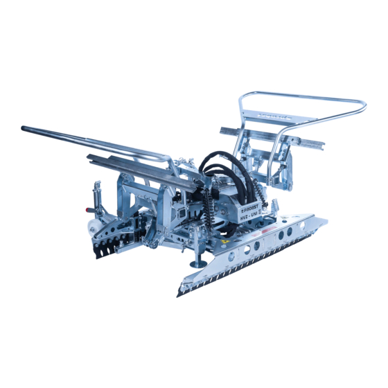
General Survey and construction Operating handle Halfen rail Rotating head (360°) Adjustment of gripping depth Height adjustment of the rollers Main clamping (facing bedding sand/planum) Main clamping (machine side) Steel lamellas Side clamping Technical data Main gripping Gripping Side gripping width Gripper Carrying capacity/working Dead... -
Page 16: Installation
Installation 5 Installation Mechanical connection The mechanical connection of the HVZ at the carrier (excavator) takes place with the universal-excavator-suspension (UBA or Lehnhofadapter). Excavator-suspension - Lehnhofadapter Make a secure connection (bolt with locking ring) between the rotating head and the excavator-suspension. Excavator-suspension (Lehnhofadapter) Safety bolt with locking... -
Page 17: Hydraulical Connection
Installation Hydraulical connection Two separate hydraulic circuit are required to connect the HVZ to the carrier The connection of the hydraulic hoses takes place on the hydraulic rotator. The opening width between the bolt sockets can be adjusted ( ) by loosening of the locking screws. -
Page 18: Adjustment Of The Hydraulic Control
Installation 5.2.1 Adjustment of the hydraulic control ● The hydraulic control is adjusted for an operating pressure (operating pressure of the carrier – e.g. excavator) of about 200 bar. ● Should the HVZ are mounted to a carrier with a higher operating pressure (e.g. -
Page 19: Adjustment „Bypass Valve" (Valve Block At Hvz)
Installation Setting 170 bar for articulated shovels/roll mops Setting 200 bar for wheel loaders Adjustment „Bypass valve“ (valve block at HVZ) The integrated bypass valve in the control block (see ) allows an adjustment of the hydraulic control to the carriers (excavators) with different oil flow volumes. -
Page 20: Adjustment Additional „Bypass-Valve" (Hydraulic Rotator/Rotating Head)
Installation Adjustment additional „Bypass-Valve“ (hydraulic rotator/rotating head) If the bypass function (of the above-described bypass valve) is not sufficient, for carriers with a larger oil flow volumes (about 60 to 80 l / min) , to ensure a trouble-free sequence of the HVZ, there is the possibility to assemble an additional ... -
Page 21: Adjustments
Adjustments 6 Adjustments General For all operations you have to make sure, that the device will not close unintended. Danger of injury!!! Caution with all adjustments exists danger of injury the hands! Adjustments of the feather-steel-lamellas ● The feather-steel-lamellas should not stitch out sideways over the contour of the laying cluster, because they could hit the already laid blocks when laying a new cluster into an edge. -
Page 22: Adjusting The Gripping Depth
Adjustments Adjusting the gripping depth 6.3.1 Facing bedding sand (planum) For all adjustments the device must be completely shut down! Caution with all adjustments exists danger of injury the hands! Adjust the gripping depth (laying side) so, that the steel- With extremely large stone layers it recommends to ⅓... - Page 23 Adjustments Pull the spring bolt upwards, rotate around 180° and Adjust the gripping depth distance approx. on 100mm - lock in position (in nick). 150 mm from the middle of the gripping depth to the outside edge of the stone layer (see stickers at the Adjust gripping depth and rotate the spring bolt again device).
-
Page 24: Machine Side
Adjustments 6.3.2 Machine Side Adjust the gripping depth (machine side) so, that the With extremely large stone layers it recommends to adjust the gripping depth a little lower, so that the steel- ½ steel-lamellas are gripping in the of the stone layer lamellas grip in the lowest range of the stone layer. -
Page 25: Height Adjustment Of The Rollers
Adjustments Height adjustment of the rollers Swing crank (1) upwards to adjust the height of the By Rotating at the crank (1) change the height of the rollers (2). height adjustable rollers (2). Distance between the steel lamellas to the lower edge of the stone layer ~ 50 mm (see picture A ) Fig. -
Page 26: Adjustment Of The Main Clamping
Adjustments Adjustment of the main clamping 6.5.1 Machine Side Adjust adjusting „C“ at the main gripping corresponding Pull main gripping in the corresponding position (). to the length of the stone layer → see sticker at the Rotate the spring bolt (3) again around 180° and lock in device (machine side). -
Page 27: Facing Bedding Sand (Planum)
Adjustments 6.5.2 Facing bedding sand (Planum) Adjust the adjusting „A“ und „D“ at the main gripping Remove safety clip at the bolt (see Fig. 16+17). corresponding to the length of the stone layer → see adjustment sticker at the device (laying side). Planum side Fig. - Page 28 Adjustments Pull main gripping in the corresponding borehole position (Fig. 19) and insert bolt again (see fig. 17). Secure bolt with safety clip (as shown in fig.17) again. Rotate the spring bolt again around 180° (as shown in fig.14) and lock in position (see adjustment sticker at the device).
-
Page 29: Pushing-Off Bar
Adjustments 6.5.3 Pushing-off bar With a stone layer breadth over 1000 mm the adjustable pushing-off bar (max. 1200 mm) should be extended. Pull out the spring plug and rotate it a little at the same time. Then let spring plug go. Then move the spring plug corresponding to the stone layer breadth. -
Page 30: Adjustment - Gripping Depth (Side Clamping)
Adjustments 6.5.5 Adjustment – gripping depth (side clamping) Adjusting screws Scale Indicator Fig. 23 Half rail ● Open the main clamping completely (by the hydraulic), which is already adjusted, then position the HVZ on the stone layer packet, so the HVZ hangs freely. ●... -
Page 31: Adjustment Of The Gripper Width
Adjustments 6.5.6 Adjustment of the gripper width Adjust side clamping (see on the left and on the right at Move the rotary protection upwards (see Fig. 25) before the side gripping side of the device ) with the adjusting the adjusting screw. adjusting screws. -
Page 32: Gripper Depth Side Clamping Direction
Adjustments 6.5.7 Gripper depth side clamping direction ● ● ● paver thickness 6 cm paver thickness 8 cm paver thickness 10 cm depth-adjustment in position 1 depth-adjustment in position 2 depth-adjustment in position 3 Adjustment weight balance When the adjusting of the main- and side clamping is finished, mind, that the device (HVZ) hangs horizontal to the working area. - Page 33 Adjustments Danger of injuring the hands! 31 / 42...
-
Page 34: Operation
Operation 7 Operation General If the arm of the carrier (excavator) is moved (with a gripped stone layer) too far to the outside, a risk of tipping of the carrier (excavator) - due to the weight of the installation clamp and the weight of the stone layer. -
Page 35: Indications For Concrete Paver Installation, Complying With The Standards
Operation Indications for concrete paver installation, complying with the standards ● It is assumed that the concrete paving stone installation units (layers of pavers), which are to be laid, comply with the requirements allowing a uniform laying pattern, complying with the standards. ●... -
Page 36: Operating Procedure Of Laying Cycle
Operation Operating procedure of laying cycle General is it the drivers obligation (of the support vehicle) to have at every time the complete working area of the carrier and the attachment in his field of view. He must ensure, that in the danger zone are either persons nor objects ●... - Page 37 Operation ● Position the HVZ over the stone layer, which shall be gripped. ● Turn the HVZ in such a way by means of the hydraulic rotator that it can be lowered over the stone layer which can be gripped. ●...
- Page 38 Operation ● In freely hanging condition of the HVZ the control lever repeated on "open" operate and there so for a long time hold, until the main clamping is completely opened and was driven out the pushing-off cylinders. This manipulation can also take place, for saving time during the HVZ is moving back (in HINT: startposition) for a new gripping action of the next stone layer.
-
Page 39: General Hints For Laying According To Standards
Operation Fig. 1 General hints for laying according to standards After the laying process is done it is necessary to move the new laid paving stones a little bit in direction of the facing bedding sand (the best way for the operating personal is to use his feet). This is the only way to achieve a standard joint (3 –... -
Page 40: General Laying-Hints
Operation General laying-hints: ● To optimize the high degree of mechanization in the mechanical paver laying it is necessary t optimize the boundary conditions. Because the laying process consists in majority of transportation and the process of paving is the smaller part it is evident to optimize the transportation on the building ground. ●... -
Page 41: Maintenance And Care
Maintenance and care 8 Maintenance and care Maintenance To ensure the correct function, safety and service life of the device the following points must be executed in the maintenance interval. Used only original spare parts, otherwise the warranty expires. All operations may only be made in unpressurised, electro less and closed state of the device! For all operations you have to make sure, that the device will not close unintended. -
Page 42: Trouble Shooting
Maintenance and care Trouble shooting ERROR CAUSE REPAIR ● ● Stone layer breaks out (downward) Main clamping is wrong Check the adjustments according adjusted (stroke 200 mm) to the adjustment sticker ● ● Stone layer is too large Adjust the gripping depth a little lower, so that the steel lamellas grip in the lower range of the stone layer... -
Page 43: Repairs
Maintenance and care Repairs ● Only persons with the appropriate knowledge and ability are allowed to repair the device. ● Before the device is used again, it has to be checked by an expert. Safety procedures • It is the contractors responsibility to ensure that the device is checked by an expert in periods of max. 1 year and all recognized errors are removed (→... -
Page 44: Hints To The Type Plate
Example: Hints to the renting/leasing of PROBST devices With every renting/leasing of PROBST devices the original operating instructions must be included unconditionally (in deviation of the users country's language, the respective translations of the original operating instructions must be delivered additionally)! - Page 45 33100184 33100183 20100017 34010099 70630001 70690041 41400945 21710026 41400955 20000026 Blatt13 20540021 34010100 33120049 41400970 Blatt10 20400004 20540036 20100015 41400977 Blatt 4/5/6 20000024 20100015 20100017 20000028 20000011 41400247 20020007 20190003 41400969 20020068 Blatt9 30320093 41401060 32200021 41400036 41400963 Blatt7/14 36400377 34010046 30300067 20100017...
- Page 46 20100014 20400001 33100271 33700111 33505702 20400001 20400004 20000234 41400274 22210041-ausgefahren 21050099 20000017 20100016 41400972 20000018 33505700 33505699 41400957 20100017 21720001 34010097 20000025 20100016 © all rights reserved conform to ISO 16016 Blatt3 Datum Name Benennung 33505213 41400975 33505698 32330007 20440005 20000018 Hydraulische Verlegezange Erst.
- Page 47 21070138 20100015 31000022 20000059 21700081 41400959 20540045 © all rights reserved conform to ISO 16016 Datum Name Benennung Hydraulische Verlegezange Erst. 6.12.2017 R.Hoffmann HVZ - uni II-Einkreis Gepr. 13.9.2018 R.Hoffmann Greifweiteneinstellung durch Spindel mit Federpaket Artikelnummer/Zeichnungsnummer Blatt E51400040 Zust. Urspr. Ers.
- Page 48 41400958 41400982 Blatt6 20100017 21720001 21720001 34010097 20000027 20000025 © all rights reserved conform to ISO 16016 Datum Name Benennung 41400983 Hydraulische Verlegezange Erst. 6.12.2017 R.Hoffmann HVZ - uni II-Einkreis Gepr. 13.9.2018 R.Hoffmann Blatt5 Greifweiteneinstellung durch Spindel mit Federpaket Artikelnummer/Zeichnungsnummer Blatt E51400040 Zust.
- Page 49 20100017 20400004 20400004 20000026 20000026 21720001 21720001 33505722 41400981 34010097 © all rights reserved conform to ISO 16016 Datum Name Benennung Hydraulische Verlegezange Erst. 6.12.2017 R.Hoffmann HVZ - uni II-Einkreis Gepr. 13.9.2018 R.Hoffmann Greifweiteneinstellung durch Spindel mit Federpaket Artikelnummer/Zeichnungsnummer Blatt E51400040 Zust.
- Page 50 20400004 20000026 21720001 20400004 34010097 21720001 33505722 © all rights reserved conform to ISO 16016 41400980 Datum Name Benennung Hydraulische Verlegezange Erst. 6.12.2017 R.Hoffmann HVZ - uni II-Einkreis 20100017 Gepr. 13.9.2018 R.Hoffmann Greifweiteneinstellung durch Spindel mit Federpaket Artikelnummer/Zeichnungsnummer Blatt E51400040 Zust.
- Page 51 20100015 20040003 41401061 30330080 20100015 21400042 30330080 21400025 20100015 22200090 20040003 20000009 41400810 30330060 21400042 20530006 21070009 20100014 41400808 20100004 20400001 33504399 20000267 20040021 41401044 Blatt 14 21400042 20100006 20100015 30330060 20000009 © all rights reserved conform to ISO 16016 Datum Name Benennung...
- Page 52 Blatt15 41401045 20100017 20400004 20100017 20000024 20440006 21710011 33100260 21800001 20440006 20000275 41400961 © all rights reserved conform to ISO 16016 Datum Name Benennung Hydraulische Verlegezange Erst. 6.12.2017 R.Hoffmann HVZ - uni II-Einkreis Gepr. 13.9.2018 R.Hoffmann Greifweiteneinstellung durch Spindel mit Federpaket Artikelnummer/Zeichnungsnummer Blatt E51400040...
- Page 53 33100271 20000234 20400001 20100014 20400001 33700111 20400004 41400966 41400519 © all rights reserved conform to ISO 16016 41400968 Datum Name Benennung Hydraulische Verlegezange Erst. 6.12.2017 R.Hoffmann HVZ - uni II-Einkreis Gepr. 13.9.2018 R.Hoffmann Greifweiteneinstellung durch Spindel mit Federpaket Artikelnummer/Zeichnungsnummer Blatt E51400040 Zust.
- Page 54 33100271 20400001 20000234 20100014 20400001 33700111 20400004 41400967 41400519 41400968 © all rights reserved conform to ISO 16016 Datum Name Benennung Hydraulische Verlegezange Erst. 6.12.2017 R.Hoffmann HVZ - uni II-Einkreis Gepr. 13.9.2018 R.Hoffmann Greifweiteneinstellung durch Spindel mit Federpaket Artikelnummer/Zeichnungsnummer Blatt E51400040 Zust.
- Page 55 33505564 20400075 41400971 20530013 © all rights reserved conform to ISO 16016 Datum Name Benennung Hydraulische Verlegezange Erst. 6.12.2017 R.Hoffmann HVZ - uni II-Einkreis Gepr. 13.9.2018 R.Hoffmann Greifweiteneinstellung durch Spindel mit Federpaket Artikelnummer/Zeichnungsnummer Blatt E51400040 Zust. Urspr. Ers. f. Ers. d.
- Page 56 21700072 20000047 32330007 41400973 41400985 32330007 20530006 20100015 20440008 20140005 © all rights reserved conform to ISO 16016 Datum Name Benennung Hydraulische Verlegezange Erst. 6.12.2017 R.Hoffmann HVZ - uni II-Einkreis Gepr. 13.9.2018 R.Hoffmann Greifweiteneinstellung durch Spindel mit Federpaket Artikelnummer/Zeichnungsnummer Blatt E51400040 Zust.
- Page 57 20020090 20100023 30320110 20000008 20540021 30320151 20100015 41400821 © all rights reserved conform to ISO 16016 Datum Name Benennung Hydraulische Verlegezange Erst. 6.12.2017 R.Hoffmann HVZ - uni II-Einkreis Gepr. 13.9.2018 R.Hoffmann Greifweiteneinstellung durch Spindel mit Federpaket 20540040 Artikelnummer/Zeichnungsnummer Blatt E51400040 Zust.
- Page 58 20140005 20400005 41400811 mit 20140005 abgebohrt © all rights reserved conform to ISO 16016 Datum Name Benennung Hydraulische Verlegezange Erst. 6.12.2017 R.Hoffmann HVZ - uni II-Einkreis Gepr. 13.9.2018 R.Hoffmann Greifweiteneinstellung durch Spindel mit Federpaket Artikelnummer/Zeichnungsnummer Blatt E51400040 Zust. Urspr. Ers. f. Ers.
- Page 59 20400001 26800009 20400001 20000004 20100014 21600024 20400004 41400960 20400004 26800006 © all rights reserved conform to ISO 16016 Datum Name Benennung Hydraulische Verlegezange Erst. 6.12.2017 R.Hoffmann HVZ - uni II-Einkreis Gepr. 13.9.2018 R.Hoffmann Greifweiteneinstellung durch Spindel mit Federpaket Artikelnummer/Zeichnungsnummer Blatt E51400040 Zust.
- Page 60 34010089 41400578 20100016 33080174 20400004 20000267 33502274 20100016 20440005 21720008 41400569 20020120 Blatt4 20440005 20000018 41800002 20100017 41400569 20020120 34010080 Blatt4 © all rights reserved conform to ISO 16016 Datum Name Benennung Fischgrät-Adapter mit RE-Messer für Erst. 25.10.2016 R.Hoffmann HVZ-uni II Gepr.
- Page 61 20100016 21720008 20440005 41800002 41400567 © all rights reserved conform to ISO 16016 Datum Name Benennung Fischgrät-Adapter mit RE-Messer für Erst. 25.10.2016 R.Hoffmann HVZ-uni II Gepr. 26.10.2016 R.Hoffmann Artikelnummer/Zeichnungsnummer Blatt E41400557-009 Zust. Urspr. Ers. f. Ers. d.
- Page 62 Blatt2 41401023 41401024 Blatt3 © all rights reserved conform to ISO 16016 Datum Name Benennung Fischgrät-Adapter mit RE-Messer für Erst. 25.10.2016 R.Hoffmann HVZ-uni II Gepr. 26.10.2016 R.Hoffmann Artikelnummer/Zeichnungsnummer Blatt E41400557-009 Zust. Urspr. Ers. f. Ers. d.
- Page 63 41400578 33080174 20000267 20400004 34010080 20100016 20100016 33502274 20100017 41400569 20020120 Blatt4 20440005 20440005 41800002 20000018 21720008 34010089 41400569 20020120 Blatt4 © all rights reserved conform to ISO 16016 Datum Name Benennung Fischgrät-Adapter mit RE-Messer für Erst. 25.10.2016 R.Hoffmann HVZ-uni II Gepr.
- Page 64 34010089 41400578 20100016 33080174 20400004 20000267 33502274 20100016 20440005 21720008 41400569 20020120 Blatt4 20440005 20000018 41800002 20100017 41400569 20020120 34010080 Blatt4 © all rights reserved conform to ISO 16016 Datum Name Benennung Fischgrät-Adapter mit RE-Messer für Erst. 25.10.2016 R.Hoffmann HVZ-uni II Gepr.
- Page 65 20100016 21720008 20440005 41800002 41400567 © all rights reserved conform to ISO 16016 Datum Name Benennung Fischgrät-Adapter mit RE-Messer für Erst. 25.10.2016 R.Hoffmann HVZ-uni II Gepr. 26.10.2016 R.Hoffmann Artikelnummer/Zeichnungsnummer Blatt E41400557-009 Zust. Urspr. Ers. f. Ers. d.
- Page 66 Baggerarmbreite / excavator arm width "B" Ø30 Ø35 Ø40 Ø50 Ø60 Ø70 Hülsensatz / sleeves set Stk./ Artikel Nr./ Pos. Beschreibung/description Länge/length Gewicht/weight Material part No. Bolzen / bolts Ø35 - Ø70 "A" Distanzbuchse Ø35x4,5x20 lang 33100075 20.0 0,1 kg S235JRG2 mit beids.
- Page 67 Detail 1 Detail Baggerarmbreite / excavator arm width "B" Ø30 Detail 2 Ø35 Ø40 Ø50 Ø60 Ø70 Bolzen / bolts Ø35 - Ø70 "A" © all rights reserved conform to ISO 16016 Distanzhülsen / spacers Datum Name Benennung Adaptersatz für UBA 1200 Erst.
- Page 68 A51400040 HVZ-UNI-II-EK A51400040-001 A51400040-002 29040666 29040773 29040775 29040056 29040221 29040774 29040210 29040221 29040367 1 / 1 P 03.08.2018_V0 Einige der Abbildungen sind möglicherweise optionales Zubehör des Gerätes/Some of pictures may be optional equipment of the device.
- Page 69 After each completed performance of a maintenance interval the included form must be fill out, stamped, signed and send back to us immediately 1) via e-mail to service@probst-handling.de / via fax or post Operator: _ _ _ _ _ _ _ _ _ _ _ _ _ _ _ _ _...
- Page 71 OPERATION AND MAINTENANCE 22500038 FR 55 22500039 FR 15 FD 30...
- Page 72 HYDRAULIC ROTATORS CONTENTS WARRANTY ..........................18 General instructions ......................18 2.1 Manufacturer identification ....................18 2.2 Markings ..........................18 2.3 Conformity declaration ......................19 2.4 Warnings, prohibitions and instructions ................20 2.5 Introduction ......................... 20 2.6 Safety rules .......................... 21 2.7 Duties of the employer ......................21 2.8 Duties of the machine operators ..................21 2.9 Decline of responsibility ......................21 STRUCTURE AND USE OF THE MANUAL .................21 GENERAL DESCRIPTION ....................22 TECHNICAL CHARACTERISTICS ..................22...
-
Page 73: Warranty
HYDRAULIC ROTATORS 1. WARRANTY 2.GENERAL INSTRUCTIONS ��������������� The warranty may be considered valid in compliancewith the contractual and administrative provisions on the part of the purchaser, and in the installation and subsequent use of the machine in compliance with the instructions contained in this manual. The manufacturer guarantees that the product was tested prior to delivery, and it is guaranteed for 12 Ferrari International S.p.A. - Via E.Tirelli, 26/a - 42122 – Reggio Emilia Italy months from the date of delivery, limited solely to Tel: +39 0522 2387 - Fax +39 0522 238799 - www.ferrariinternational.com manufacturing and assembly defects. The warranty does not cover: • Labour 2.2 Markings • All parts that by their specific use are subject to wear and tear The equipment has been constructed in compliance • The costs of shipping, inspection, and labour with the relevant EU Directives applicable at when the defects found are not attributable to the the moment of its release on the market since manufacturer. the equipment is compliant to the declaration in accordance with art. 2, letter a) second point, a specific The manufacturer undertakes to repair or replace free self-certification of conformity CE Enc. II A is issued. of charge any parts that show to be defective at the outset. In this regard the judgement expressed by our The plate applied must be similar to the one shown Authorised Service technicians will be considered final. -
Page 74: Conformity Declaration
HYDRAULIC ROTATORS 2.3 Conformity declaration Enclosed with the manual is the required conformity declaration similar to the one shown below and duly completed with the customer’s specific data. Dichiarazione di conformità (All. Il - P.1 Sez.A) / Declaration of conformità (All. Il - P.1 Sez.A) XXXXX Del / dated / du XX/XX/2019 Erklarung von der Ubereinstimmung (All. Il - P.1 Sez.A) / Declaration de conformitè (All. Il - P.1 Sez.A) vom / del / de Declaraçion do conformidad (All. -
Page 75: Warnings, Prohibitions And Instructions
HYDRAULIC ROTATORS 2.4 Warnings, prohibitions and instructions 2.6 Norme di sicurezza Before using the equipment, verify the presence of the adhesive labels according to the diagram below. It is strictly prohibited to pass within the range of action of the machine and the equipment. SYMBOL MEANING POSITION Prohibited to Danger of suspended loads clean, lubricate, On the adjust or repair machine with machine running Danger of crushing Danger of On the crushing machine Danger of entanglement It is prohibited for the user to remove the adhesive labels. It is strictly prohibited to use the equipment before having blocked access to the work area by persons and animals; for this purpose it is necessary to enclose the work area 2.5 Introduction and to adopt any appropriate measures to make all the work operations safe. -
Page 76: Safety Rules
HYDRAULIC ROTATORS suitable to use the machine, who must be given proper the information necessary for proper usage of the instruction on the lifting capacities and limits of use, equipment as well as to manage it in the safest and and who must also know and scrupulously follow the most autonomous way possible. safety rules regarding lifting loads The manual in cludes information regarding the 2.7 Duties of the employer technical aspects, operation, machine stoppage, maintenance, spare parts and safety. The employer is responsible for providing this manual to all the personnel who will interact with the machine. Before carrying out any operation on the equipment, operators and qualified technicians must carefully read 2.8 Duties of the machine operators the instructions contained in this manual. In addition to the duty to scrupulously follow all the In case of any doubts as to the correct interpretation of instructions contained in this manual, the operators the instructions, please contact our office to obtain the must notify their supervisors of any deficiency or necessary clarification. potentially dangerous situation that may arise. This manual is an integral part of the In the event of a malfunction of the equipment and must be properly preserved equipment, verify the procedures by the purchaser. described in the various chapters. -
Page 77: General Description
HYDRAULIC ROTATORS 4. GENERAL DESCRIPTION The rotator is equipped with hydraulic hoses that are connected following the instructions shown by the symbols situated on the head and on the shaft. The FERRARI INTERNATIONAL S.p.A. hydraulic rotator is designed to be installed on the end of the crane boom 5. TECHNICAL and allows the connection and use of equipment such as buckets, polyp grabs, forks, and so on. CHARACTERISTICS SHAFT VERSION FR 15 FR 35 FR 50 FR 55 Models Static load Dinamic load Weight Pressure Rotation Torque Oil flow l/min FR 15 1200 360°... - Page 78 HYDRAULIC ROTATORS SHAFT VERSION FR 85 SX FR 85 SX/2 FR 128 SX FR 128 SX/2 Models Static load Dinamic load Weight Pressure Rotation Torque Oil flow l/min FR 85 SX 7000 3500 360° cont. 1900 FR 85 SX/2 7000 3500 360°...
- Page 79 HYDRAULIC ROTATORS FLANGED VERSION FR 35 F FR 50 F FR 55 F Models Static load Dinamic load Weight Pressure Rotation Torque Oil flow l/min FR 35 F 3500 1750 360° cont. FR 50 F 5000 2500 360° cont. 1100 FR 55 F 5500 2700...
- Page 80 HYDRAULIC ROTATORS FLANGED VERSION FR 85 SXF FR 85 SXF/2 FR 128 SX-F FR 128 SX-F/2 Models Static load Dinamic load Weight Pressure Rotation Torque Oil flow l/min FR 85 SXF 7000 3500 360° cont. 1900 FR 85 SXF/2 7000 3500 360°...
- Page 81 HYDRAULIC ROTATORS 6 WAY VERSION FR 50 F S6X FR 128 F S6X Models Static load Dinamic load Weight Pressure Rotation Torque Oil flow l/min FR 50 F S6X 5000 2500 360° cont. 1100 FR 128 F S6X 12000 6000 360°...
-
Page 82: Installation
HYDRAULIC ROTATORS 6. INSTALLATION 6.2 Assembly The hydraulic system of the machine must be 6.1 Handling equipped to power the equipment. For lifting and transporting, use means If the machine in the original version is not equipped adequate to the weight to be moved. for this purpose, it is necessary to modify the hydraulic system to adapt it to the present requirements. To ensure safe transport, the equipment must be securely fastened onto a pallet. This modification must only be carried out by authorised personnel from the machine Lifting is carried out together with the pallet using manufacturer. a lift truck or by harnessing as shown in the figure, providing belts with a suitable capacity. ���������� For fitting on the crane boom, the upper part of See the weight of the components indicated the rotator is equipped with a coupling fork, with a in Chapter 5 - Technical Characteristics. fastening pin passed inside it that is secured with a safety split pin. Move the load by lifting it very slowly in order not to create sudden movements that could give rise to The rotator must always hang free vertically with dangerous situations. respect to the shaft. Make sure to limit the possibility of rotator oscillation The personnel assigned to moving and and protect it from the hydraulic system hoses to handling must wear: protective gloves, hard prevent it from being damaged. hat, and safety shoes with steel toe and non-skid sole. -
Page 83: Cleaning
HYDRAULIC ROTATORS 6.3 Cleaning 7.2 Improper use The equipment can be cleaned by Any type of use not expressly indicated in Chapter 7.1 personnel who do not have specific is to be considered IMPROPER USE. technical skills, but they must be informed beforehand of the need to perform this The manufacturer may not be held operation only when the machine is responsible for any damage to things, stopped in order not to cause dangerous persons, or to the machine resulting from situations. accidents caused by an improper use of the equipment. 6.4 Demolition and disposal 7.3 PPE Before proceeding to the demolition of the equipment, it is mandatory to eliminate As necessary or required by the internal regulations, and dispose of all the parts that may be personal protective equipment must be used. harmful to the environment, according to the local laws and regulations. Personal protective equipment (PPE) comprises clothing and accessories to be worn by the workers to Elements in plastic: protect them from the specific risks of the activity must be removed and disposed of separately. being carried out. Lubricants: The employer must provide the PPE, choosing it in must be collected and taken to the dedicated collection... -
Page 84: Operation
HYDRAULIC ROTATORS ������������� - Lift the load from the base or from the ground before proceeding to transfer or rotate it. The personnel assigned to operate the machine, - It is prohibited to leave the suspended load before starting the work, must have studied the chapter unattended. “Safety Rules”. This is especially important for - Make sure that the hoses do not come into contact personnel using the machine only sporadically. with obstacles of any type. Check periodically that the personnel, while working, - Breakage of the hoses or a nipple can cause are following the safety and accident prevention rules uncontrolled rotation and the load could be dropped. indicated in the instruction manual. Establish the responsibilities of the operator of the machine and authorise him to refuse to follow any 9. MAINTENANCE directions given by other persons that are contrary to the safety rules. Any trainee or student personnel may work with the Maintenance must be a scheduled preventive activity, machine or the system only under the constant viewed as a fundamental requirement for the purpose supervision of experienced personnel. of safety, with the assumption that the machines and the equipment are subject to wear and tear that is a potential cause of breakdowns. 8. OPERATION Therefore, the safety of the machines also depends Before using the equipment, read all the information in on good preventive maintenance that enables the the chapter “Safety Rules”. -
Page 85: Service
HYDRAULIC ROTATORS 10. SPARE PARTS The extraction of the pins may cause unpredictable movements in the structural work: immobilise the parts To identify a spart part, follow the procedure described before performing any operation. below: - Locate the part and its position number on the Use only original spare parts. specific drawing of the assembly. - Consult the table and, in correspondence with the For spare parts orders, please specify: position, find the information necessary for ordering - MODEL the part: - SERIAL NO. • Code - YEAR OF MANUFACTURE • Description of the part • Quantities fitted on the machine (Qty) To be performed every 500 working hours: - Complete the order form and FERRARI - verify that the play between pin and bush is less than INTERNATIONAL S.p.A. will supply the spare parts. 0.6 mm; if greater, replace the worn parts; - check the seal of the cylinder gaskets and replace if We recommend that you record in the manual the necessary;... - Page 86 FR 55 F/30 9.482 240.8 1.181 2.874 6.772 0.669 <R R> 5.512 ROTATION ANGLE UNLIMITED MAX PRESSURE (R) [BAR/PSI] 3625 2901 MAX PRESSURE (GO) [BAR/PSI] MAX PRESSURE (GC) [BAR/PSI] 4351 DISPLACEMENT [cm3/Inch3] TORQUE [Nm/lbf-ft] 1100 MAX AXIAL LOAD STATIC [KN/lbf] 12365 MAX AXIAL LOAD DYNAMIC [KN/lbf] 6070...
- Page 87 FR 15 7.639 194.02 0.984 1.766 5.394 1.555 0.787 39.5 R> <R ROTATION ANGLE UNLIMITED MAX PRESSURE (R) [BAR/PSI] 3625 MAX PRESSURE (GO) [BAR/PSI] 2901 MAX PRESSURE (GC) [BAR/PSI] 4351 DISPLACEMENT [cm3/Inch3] TORQUE [Nm/lbf-ft] MAX AXIAL LOAD STATIC [KN/lbf] 2248 MAX AXIAL LOAD DYNAMIC [KN/lbf] 1124 WEIGHT [kg/lb]...
Need help?
Do you have a question about the HVZ-UNI-II-EK and is the answer not in the manual?
Questions and answers