
Related Manuals for Star Lake AV710-X3


Summary of Contents for Star Lake AV710-X3
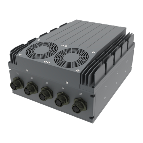
- Page 1 Version 1.0 Quick Installation Guide Revision Date: 03.15.2022 AV710-X3 IP65 MXM-GPU Server with Intel Xeon D-1577 processor, MIL-STD- 461 EMI 18-36V DC-In...
-
Page 2: Safety Information
Safety information Electrical safety To prevent electrical shock hazard, disconnect the power cable from the electrical outlet before relocating the system. When adding or removing devices to or from the system, ensure that the power cables for the devices are unplugged before the signal cables are connected. If possible, disconnect all power cables from the existing system before you add a device. -
Page 3: Revision History
Revision History Revision Date (yyyy/mm/dd) Changes Version 1.0 2022/03/15 Initial release Packing list AV710-X3 IP65 MXM-GPU Server System CD (Driver + Quick Installation Guide) Ordering information De Scription] Model Number AV710-X3 Military MXM-GPU Server with Intel Xeon D-1577 Processor, IP65 rating, MIL-STD-D38999 Connectors, 18~36V DC-in, Extreme Rugged Operating Temperature -40 to 60°C... -
Page 4: Table Of Contents
Table Contents SAFETY INFORMATION ................................2 LECTRICAL SAFETY ............................................PERATION SAFETY ............................................STATEMENT ....................................2 REVISION HISTORY ..................................3 PACKING LIST ....................................3 ORDERING INFORMATION ............................. 3 TABLE CONTENTS ....................................4 CHAPTER 1: PRODUCT INTRODUCTION ..........................5 • K EATURES ..........................................•... -
Page 5: Chapter 1: Product Introduction
Chapter 1: Product Introduction • Key Features System Intel® Xeon® Processor D-1577 Processor (24M Smart Cache, 16 Cores/ 32 Threads, Base Frequency 1.3GHz; Max Turbo Frequency 2.1 GHz) Memory Type Supports up to 256GB DDR4 ECC RDIMM Graphics Card Nvidia Quadro RTX5000 MXM (16GB DDR6, 3072 CUDA Cores) BIOS AMI®... -
Page 6: Dimensions
• Dimensions... - Page 7 • Panel Component GbE LAN label (X1) 10GbE Copper LAN, label (X2) 10GbE Copper LAN, label (X3) DVI-D, label (X4) COM, label (X5) DC In, Label (X6) Waterproof valve, label (X7) Power Button with LED backlight...
-
Page 8: Chapter 2: Jumpers And Connectors Locations
Chapter 2: Jumpers and Connectors Locations D38999 Connector Pin Definitions (X1): GbE LAN (X2): 10GbE LAN (X3): 10GbE LAN... -
Page 9: Connector X4, X5, X6
(X4): DVI-D (X5): COM (X6): DC-In... -
Page 10: Chapter 3: Bios Setup
BIOS Setup 3. • 3.1 Menu Structure This section presents the six primary menus of the BIOS Setup Utility. Use the following table as a quick reference for the contents of the BIOS Setup Utility. The subsections in this section describe the submenus and setting options for each menu item. The default setting options are presented in bold, and the function of each setting is described in the right-hand column of the respective table. - Page 11 • 3.1.4 Main > Board Information Feature Options Description Board Information Submenu Board Information Info only Serial Number Info only Display SEMA serial Number. Manufacturing Date Info only Display SEMA manufacturing date. Last Repair Date Info only Display SEMA last repair date. MAC ID Info only Display SEMA MAC ID.
- Page 12 Emulation AT/ATX Emulation AT Select Emulation AT or ATX function. If this option is set to [Emulation AT], BIOS will report no suspend functions to ACPI OS. In windows XP, it will make OS show shutdown LID Function Enable/Disable LID Function Disabled Enabled Lock Legacy Resource...
- Page 13 BIOS Select Info Only ATX/AT-Mode Info Only Exception Code Info Only • 3.2.4 Advanced > Thermal Management Feature Options Description Thermal Configuration Parameters Info Only Thermal and Fan Speed Submenu Smart Fan Submenu Critical Trip Point Disabled The value is the temperature threshold of the Critical 65 C Trip Point.
- Page 14 Feature Options Description Board Temperature Info Only Current Info Only Display Current Board Temperature Startup Info Only Display Startup Board Temperature Info Only Display Min Board Temperature Info Only Display Max Board Temperature CPU Fan Speed Info Only Display CPU Fan Speed •...
- Page 15 Feature Options Description Boot option filter UEFI and Legacy This option controls Legacy/UEFI ROMs priority Legacy only UEFI only Option ROM execution Info only Network Do not launch Controls the execution of UEFI and Legacy PXE OpROM UEFI Legacy Storage Do not launch Controls the execution of UEFI and Legacy Storage UEFI...
- Page 16 • 3.2.7.2 Advanced > Super IO Configuration > Serial Port 2 Configuration (NCT5104D) Feature Options Description Serial Port 2 Configuration Submenu Set Parameters of Serial Port 2 (COMB). Serial Port 2 Configuration Info only Serial Port Enable or Disable Serial Port (COM). Disableed Enabled Device Settings...
- Page 17 • 3.2.8 Advanced > Serial Console Redirection Feature Options Description COM1 Info only Console Redirection Console Redirection Enable or Disable. Enabled Disabled Console Redirection Settings Submenu The settings specify how the host computer and the remote computer (which the user is using) will exchange data.
- Page 18 • 3.2.8.1 Advanced > Serial Console Redirection > Console Redirection Settings (If COM1 Enable) Feature Options Description COM1 Info only Console Redirection Settings Info only Teriminal Type Emulation: VT100 ANSI: Extended ASCII char set. VT100+ VT100: ASCII char set. VT-UTF8 ANSI VT100+: Extends VT100 to support color, function keys, etc.
- Page 19 Feature Options Description Redirection After BIOS POST Always Enable When Bootloader is selected, then Legacy Console BootLoader Redirection is disabled before booting to legacy OS. When Always Enable is selected, then Legacy Console Redirection is enabled for legacy OS. Default setting for this option is set to Always Enable.
- Page 20 Feature Options Description Putty KeyPad Select FunctionKey and KeyPad on Putty. VT100 Intel Linux XTERMR6 ESCN VT400 Redirection After BIOS POST Always Enable When Bootloader is selected, then Legacy Console BootLoader Redirection is disabled before booting to legacy OS. When Always Enable is selected, then Legacy Console Redirection is enabled for legacy OS.
- Page 21 Feature Options Description Resolution 100x31 Enabled On Legacy OS, the Number of Rows and Columns Disabled supported redirection 80x24 Legacy OS Redirection On Legacy OS, the Number of Rows and Columns Resolution 80x25 supported redirection Putty KeyPad Select FunctionKey and KeyPad on Putty. VT100 Intel Linux XTERMR6...
- Page 22 Feature Options Description VT-UTF8 Combo Key Support Enabled Enable VT-UTF8 Combination Key Support for Disabled ANSI/VT100 terminals Recorder Mode Disabled With this mode enabled only text will be sent. Enabled This is to capture Terminal data. Resolution 100x31 Enabled On Legacy OS, the Number of Rows and Columns Disabled supported redirection 80x24...
- Page 23 Feature Options Description USB hardware delays and time-outs: Info Only USB transfer rime-out 1 sec The time-out value for Control, Bulk, and Interrupt 5sec transfers. 10sec 20 sec Device reset time-out 10 sec USB mass storage device Start Unit command time- 20 sec out.
- Page 24 • 3.2.13 Advanced > Trusted Computing Feature Options Description TPM20 Device Found Info Only Security Device Support Enables or Disable BIOS support for security device. Disable OS will not show Security Device. Enable TCG EFI protocol and available. Active PCR banks Info Only Feature Options...
- Page 25 • 3.3 Chipset • 3.3.1 Chipset > Processor Configuration Feature Options Description Processor Configuration Info only Processor Socket Info only Display Processor Socket information Processor ID Info only Display Processor Socket information Processor Frequency Info only Display Processor Frequency information Processor Max Ratio Info only Display Processor Max Ratio information...
- Page 26 Feature Options Description CPU P State Control Submenu Controls CPU frequency. CPU C State Control Submenu Control CPU idle states Long Pwr Limit Ovrd Disable Enable/Disable Long Term Power Limit override. If this option is disabled, BIOS will program the default values for Long Term Power Limit and Long Term Power Limit Time Window.
- Page 27 Feature Options Description CPU C3 report Disable Enable/Disable CPU C3(ACPI C2) report to OS. Recommended to be disabled. Enable CPU C6 report Disable Enable/Disable CPU C6(ACPI C2) report to OS Enable Recommended to be enabled. Enhanced Halt State (C1E) Disable Enables the Enhanced C1E state of the CPU, takes Enable effect after reboot.
- Page 28 • 3.3.4.1 Chipset > IIO Configuration > IIO0 Configuration Feature Options Description IOU2 (IIO PCIe Port 1) Select PCIe port Bifurcation for selected slot(s) x4x4 Auto IOU1 (IIO PCIe Port 3) x4x4x4x4 Select PCIe port Bifurcation for selected slot(s) x4x4x8 x8x4x4 x8x8 Auto...
- Page 29 Feature Options Description Fatal Err Over Disable Enables forcing fatal error propagation to the IIO core error logic for this port Enable Non-Fatal Err Over Disable Enables forcing non-fatal error propagation to the IIO core error logic for this port Enable Corr Err Over Disable...
- Page 30 Feature Options Description P7 (-6.0/3.5 dB) P8 (-3.5/3.5 dB) P9 (0.0/3.5 dB) Hide Port? User can force to hide this root port from OS Pcie Ecrc Enable/Disable Pcie Ecrc Support for this port. Disable Enable Auto Chipset > IIO Configuration > IIO0 Configuration > Socket 0 PcieD02F2 – Port 2C Feature Options Description...
- Page 31 Feature Options Description PM ACPI Mode Disable When Disabled, MSI is generated on PM event. When Enabled, _HPGPE message is generated Enable Gen3 Eq Mode Auto PCIe Gen3 Adaptive Equilization Mode Enable Phase 0,1,2,3 Disable Phase 0,1,2,3 Enable Phase 1 Only Enable Phase 0,1 Only Advanced Enable MMM Offset West...
- Page 32 Chipset > IIO Configuration > IIO0 Configuration > Socket 0 PcieD03F0 – Port 3A Feature Options Description Info only Socket 0 PcieD03F0 – Port PCI-E Port Auto In auto mode the BIOS will remove the EXP port if there is no device or errors on that device and the Enable device is not HP capable.
- Page 33 Feature Options Description Gen3 Spec Mode Auto PCIe Gen3 Spec Mode 0.70 July • Sept • Sept Gen3 Phase2 Mode Hardware Adaptive Manual Gen3 DN Tx Present Auto PCIe Gen3 Downstream Tx Present P0 (-6.0/0.0 dB) P1 (-3.5/0.0 dB) P2 (-4.5/0.0 dB) P3 (-2.5/0.0 dB) P4 (0.0/0.0 dB) P5 (0.0/2.0 dB)
- Page 34 Feature Options Description ACS Control Enable Enable: Programs ACS only to Chipset Pcie Root Ports Bridges; Disable Disable: Programs ACS to all Pcie bridges Interrupt Remapping Enable Enable/Disable VT_D Interrupt Remapping Support Disable Coherency Support (Non-Isoch) Enable Enable/Disable Non-Isoch VT_D Engine Coherency support Disable Coherency Support (Isoch)
- Page 35 • 3.3.5.1 Chipset > IIO Configuration > IIO0 Configuration Feature Options Description IOU2 (IIO PCIe Port 1) Select PCIe port Bifurcation for selected slot(s) x4x4 Auto IOU1 (IIO PCIe Port 3) x4x4x4x4 Select PCIe port Bifurcation for selected slot(s) x4x4x8 x8x4x4 x8x8 Auto...
- Page 36 Feature Options Description Fatal Err Over Disable Enables forcing fatal error propagation to the IIO core error logic for this port Enable Non-Fatal Err Over Disable Enables forcing non-fatal error propagation to the IIO core error logic for this port Enable Corr Err Over Disable...
- Page 37 Feature Options Description P7 (-6.0/3.5 dB) P8 (-3.5/3.5 dB) P9 (0.0/3.5 dB) Hide Port? User can force to hide this root port from OS Pcie Ecrc Enable/Disable Pcie Ecrc Support for this port. Disable Enable Auto Chipset > IIO Configuration > IIO0 Configuration > Socket 0 PcieD02F2 – Port 2C Feature Options Description...
- Page 38 Feature Options Description PM ACPI Mode Disable When Disabled, MSI is generated on PM event. When Enabled, _HPGPE message is generated Enable Gen3 Eq Mode Auto PCIe Gen3 Adaptive Equilization Mode Enable Phase 0,1,2,3 Disable Phase 0,1,2,3 Enable Phase 1 Only Enable Phase 0,1 Only Advanced Enable MMM Offset West...
- Page 39 Chipset > IIO Configuration > IIO0 Configuration > Socket 0 PcieD03F0 – Port 3A Feature Options Description Info only Socket 0 PcieD03F0 – Port PCI-E Port Auto In auto mode the BIOS will remove the EXP port if there is no device or errors on that device and the Enable device is not HP capable.
- Page 40 Feature Options Description Gen3 Spec Mode Auto PCIe Gen3 Spec Mode 0.70 July • Sept • Sept Gen3 Phase2 Mode Hardware Adaptive Manual Gen3 DN Tx Present Auto PCIe Gen3 Downstream Tx Present P0 (-6.0/0.0 dB) P1 (-3.5/0.0 dB) P2 (-4.5/0.0 dB) P3 (-2.5/0.0 dB) P4 (0.0/0.0 dB) P5 (0.0/2.0 dB)
- Page 41 Feature Options Description ACS Control Enable Enable: Programs ACS only to Chipset Pcie Root Ports Bridges; Disable Disable: Programs ACS to all Pcie bridges Interrupt Remapping Enable Enable/Disable VT_D Interrupt Remapping Support Disable Coherency Support (Non-Isoch) Enable Enable/Disable Non-Isoch VT_D Engine Coherency support Disable Coherency Support (Isoch)
- Page 42 • 3.5 Boot Feature Options Description Boot Configuration Info only Setup Prompt Timeout Number of seconds to wait for setup activation key. 65535(0xFFFF) means indefinite waiting. Bootup NumLock State Select the keyboard Number state. Ouiet Boot Select the keyboard NumLock state. Disabled Enabled Fast Boot...
- Page 43 4. BIOS Checkpoints, Beep Codes This section of this document lists checkpoints and beep codes generated by AMI Aptio BIOS. The checkpoints defined in this document are inherent to the AMIBIOS generic core, and do not include any chipset or board specific checkpoint definitions. Checkpoints and Beep Codes Definition A checkpoint is either a byte or word value output to I/O port 80h.
- Page 44 • 4.1 Status Code Ranges Status Code Description Range 0x01 – 0x0B SEC execution 0x0C – 0x0F SEC errors 0x10 – 0x2F PEI execution up to and including memory detection 0x30 – 0x4F PEI execution after memory detection 0x50 – 0x5F PEI errors 0x60 –...
- Page 45 SEC Error Codes 0x0C – 0x0D Reserved for future AMI SEC error codes 0x0E Microcode not found 0x0F Microcode not loaded • 4.1.2 SEC Beep Codes None • 4.1.3 PEI Phase Status Code Description Progress Codes 0x10 PEI Core is started 0x11 Pre-memory CPU initialization is started 0x12...
- Page 46 Status Code Description 0x35 CPU post-memory initialization. Boot Strap Processor (BSP) selection 0x36 CPU post-memory initialization. System Management Mode (SMM) initialization 0x37 Post-Memory North Bridge initialization is started 0x38 Post-Memory North Bridge initialization (North Bridge module specific) 0x39 Post-Memory North Bridge initialization (North Bridge module specific) 0x3A Post-Memory North Bridge initialization (North Bridge module specific) 0x3B...
- Page 47 Status Code Description S3 Resume Error Codes 0xE8 S3 Resume Failed 0xE9 S3 Resume PPI not Found 0xEA S3 Resume Boot Script Error 0xEB S3 OS Wake Error 0xEC-0xEF Reserved for future AMI error codes Recovery Progress Codes 0xF0 Recovery condition triggered by firmware (Auto recovery) 0xF1 Recovery condition triggered by user (Forced recovery) 0xF2...
- Page 48 • 4.1.5 DXE Status Codes Status Code Description 0x60 DXE Core is started 0x61 NVRAM initialization 0x62 Installation of the South Bridge Runtime Services 0x63 CPU DXE initialization is started 0x64 CPU DXE initialization (CPU module specific) 0x65 CPU DXE initialization (CPU module specific) 0x66 CPU DXE initialization (CPU module specific) 0x67...
- Page 49 Status Code Description 0x95 PCI Bus Request Resources 0x96 PCI Bus Assign Resources 0x97 Console Output devices connect 0x98 Console input devices connect 0x99 Super IO Initialization 0x9A USB initialization is started 0x9B USB Reset 0x9C USB Detect 0x9D USB Enable 0x9E –...
- Page 50 Status Code Description 0xB8 – 0xBF Reserved for future AMI codes 0xC0 – 0xCF OEM BDS initialization codes DXE Error Codes 0xD0 CPU initialization error 0xD1 North Bridge initialization error 0xD2 South Bridge initialization error 0xD3 Some of the Architectural Protocols are not available 0xD4 PCI resource allocation error.
- Page 51 Status Code Description 0x10 System is waking up from the S1 sleep state 0x20 System is waking up from the S2 sleep state 0x30 System is waking up from the S3 sleep state 0x40 System is waking up from the S4 sleep state 0xAC System has transitioned into ACPI mode.
Need help?
Do you have a question about the AV710-X3 and is the answer not in the manual?
Questions and answers