
Related Manuals for Star Lake OXY5740A


Summary of Contents for Star Lake OXY5740A
- Page 1 OXY5740A Intel® 7th Gen.Kabylake-H Core™ i7 Processor,Stackable with PCIe/104 & FPE Expansion,Extended Temp.-40 to 85°C User’s Manual Revision Date: November 11 2019...
-
Page 2: Safety Information
OXY5740A User’s Manual Revision Date: November 11 2019 Safety Information Electrical safety To prevent electrical shock hazard, disconnect the power cable from the electrical outlet before relocating the system. When adding or removing devices to or from the system, ensure that the power cables for the devices are unplugged before the signal cables are connected. -
Page 3: Revision History
□ CD (Driver + user's manual) □ Optional Accessories • 1 x terminal block • [Optional] Cable kit for OXY5740A: 1 x SATA, 1 x SATA power, 1 x COM If any of the above items is damaged or missing, please contact your local distributor. -
Page 4: Table Of Contents
OXY5740A User’s Manual Revision Date: November 11 2019 Table of Contents Safety Information ............................1 Electrical safety ............................1 Operation safety .............................1 Statement ..............................1 Revision History ............................1 Packing list ..............................1 Chapter 1: Product Information ......................1 1.1 Block Diagram ...........................5 1.2 Key Features ............................6... - Page 5 OXY5740A User’s Manual Revision Date: November 11 2019 ................4.4.5 IT8786 Super IO Configuration ....................4.4.6 Hardware Monitor ....................4.4.7 CSM Configuration 4.5 Chipset ............................35 ....................4.5.1 SA Configuration …………………… ............4.5.1.1 Graphics Configuration ……………… ................4.5.1.2 LCD Control ……………………………...
-
Page 6: Block Diagram
OXY5740A User’s Manual Revision Date: November 11 2019 Chapter 1: Product Information 1.1 Block Diagram... -
Page 7: Key Features
OXY5740A User’s Manual Revision Date: November 11 2019 1.2 Key Features System Intel® Kabylake-H Core™ Processor Intel® Core™ i7-7820QE Processor (4 Cores/8 Threads, 8M Cache,up to 3.70GHz), 45W Chipset Intel® QM175 Memory Type 1 x SO-DIMM up to 32GB NAND Flash... - Page 8 OXY5740A User’s Manual Revision Date: November 11 2019 LVDS Mechanical and Environment Form Factor Power Type DC-IN 12V 203mm x 146mm Dimension Operating Temp. -40 to 85°C Storage Temp -40 to 85°C Relative Humidity 10% to 90%, non-condensing Standard Compliance...
-
Page 9: Board Placement
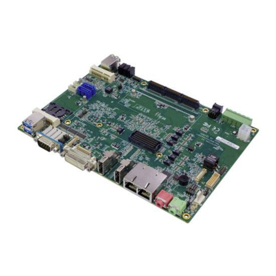
OXY5740A User’s Manual Revision Date: November 11 2019 1.3 Board Placement... -
Page 10: Chapter 2: Jumpers And Connectors
OXY5740A User’s Manual Revision Date: November 11 2019 Chapter 2: Jumpers and Connectors 2.1 Jumpers and connectors list Label Function BAT1 BATTERY connector DIMM0 DDR4 SO DIMM Socket DIMM1 DDR4 XR DIMM Socket CN19 LVDS CONNECTOR MCARD1 Mini PCIE Card Slot<Full size Co-lay mSATA>... - Page 11 OXY5740A User’s Manual Revision Date: November 11 2019 CN22 4P DC Terminal Block connector CPU FAN CPU FAN CONNECTOR FPE1 StackPC FPE Top Connector CON_A1 StackPC LED1 LAN1 LED STATUS LED2 LAN2 LED STATUS LED3 POWER/HDD LED POWER BUTTON CN18...
-
Page 12: Jumper Settings
OXY5740A User’s Manual Revision Date: November 11 2019 2.2 Jumper Settings CN2: LVDS Connector PIN DEFINITION PIN DEFINITION LVDS_BCLK LVDS_BCLK# LVDS_A3 LVDS_A3# LVDS_B3 LVDS_B3# LVDS_ACLK LVDS_B2 LVDS_ ACLK # LVDS_B2# LVDS_B1 LVDS_A2 LVDS_B1# LVDS_A2# LVDS_B0 LVDS_A1 LVDS_B0# LVDS_A1# LVDS_A0 LVDS_DCC_SC... - Page 13 OXY5740A User’s Manual Revision Date: November 11 2019 CN18: Inverter connector PIN DEFINITION 1 12V 2 12V 3 12V 4 5VS 5 5VS 6 GND 7 GND 8 BL_EN 9 LVDS_BKL_CTRL_R 10 GND CPU FAN: CPU FAN Connector DEFINITION CPUFAN_PWN...
- Page 14 OXY5740A User’s Manual Revision Date: November 11 2019 JP14: MCARD1 mSATA and mPCIe selection Jumper Function description Setting mPCIe mSATA Default setting: 1-2 MCARD1: Mini PCIE Card Slot<COLAY M SATA>...
- Page 15 OXY5740A User’s Manual Revision Date: November 11 2019 MCARD2: Mini PCIE Card Slot...
- Page 16 OXY5740A User’s Manual Revision Date: November 11 2019 LAN1: Intel I219LM / LAN2: Intel I210IT CN20: USB 2.0 PIN DEFINITION 1 5V 2 USB1- 3 USB1+ 4 GND 5 GND 6 5V 7 USB2- 8 USB2+ 9 GND 10 GND CN21: USB 2.0...
- Page 17 OXY5740A User’s Manual Revision Date: November 11 2019 CN8: USB3.0 * 2 CN9: USB3.0 * 2 CN6: Audio Jacks Connector (MIC) CN7: Audio Jacks Connector (Line-Out)
- Page 18 OXY5740A User’s Manual Revision Date: November 11 2019 CN22: DC Adapter Power Input DC_JACK1: DC-IN CN10: LPC (Update BIOS)
- Page 19 OXY5740A User’s Manual Revision Date: November 11 2019 DP1: DISPLAY PORT DP2: DISPLAY PORT SIM_CARD1: SIM card socket...
- Page 20 OXY5740A User’s Manual Revision Date: November 11 2019 DVI: DVI-D COM1: RS232/422/485 with 5V/12V selectable JP4: COM1 5V/12V selection JP5: COM2 5V/12V selection...
- Page 21 OXY5740A User’s Manual Revision Date: November 11 2019 COM2: RS232, with 5V/12V selectable COM3/4: RS232...
- Page 22 OXY5740A User’s Manual Revision Date: November 11 2019 CON A1: CONNECTOR A TOP...
- Page 23 OXY5740A User’s Manual Revision Date: November 11 2019 FPE1: StackPC FPE Top Connector...
- Page 24 OXY5740A User’s Manual Revision Date: November 11 2019 LED1: LAN1 LED STATUS LED2: LAN2 LED STATUS LED3: POWER/HDD LED SW1: POWER BUTTON...
- Page 25 OXY5740A User’s Manual Revision Date: November 11 2019 FP1: Front Panel FP2: LAN LED Plug LED cable to FP2 pin header Active LED: plug 1-3 pin Single 1000M LED: plug 1-5 pin Single 100M LED: plug 1-7 pin Dual 1000M LED: plug 5-7 pin...
-
Page 26: Chapter 3: Getting Started
Revision Date: November 11 2019 Chapter 3: Getting Started 3.1 Installing System Memory The OXY5740A supports 1 x DDR4 XR-DIMM up to 16GB (Top Side), 1 x DDR4 SODIMM up to 16GB. To install a memory module: 1. Located the memory module slots on the motherboard. - Page 27 OXY5740A User’s Manual Revision Date: November 11 2019 3. Insert the module firmly into the desired slot until the slot lock and secure the memory module. 4. After insert the module to the desire slot, drive screws tighten with memory...
-
Page 28: Chapter 4: Jumpers And Connectors
OXY5740A User’s Manual Revision Date: November 11 2019 Chapter 4: AMI BIOS UTILITY This chapter provides users with detailed descriptions on how to set up a basic system configuration through the AMI BIOS setup utility. 4.1 Starting To enter the setup screens, perform the following steps: •... -
Page 29: Mani Menu
OXY5740A User’s Manual Revision Date: November 11 2019 4.3 Main Menu The Main menu is the screen that first displays when BIOS Setup is entered, unless an error has occurred. System Date Use this function to change the system date. -
Page 30: Advanced Menu
OXY5740A User’s Manual Revision Date: November 11 2019 Access Level Display the access level of the current user in the BIOS. 4.4 Advanced Menu The Advanced Menu allows you to configure your system for basic operation. Some entries are defaults required by the system board, while others, if enabled, will improve the performance of your system or let you set some features according to your preference. -
Page 31: Cpu Configuration
OXY5740A User’s Manual Revision Date: November 11 2019 4.4.1 CPU Configuration 4.4.2 Power & Performance... -
Page 32: Pch-Fw Configuration
OXY5740A User’s Manual Revision Date: November 11 2019 4.4.3 PCH-FW Configuration 4.4.4 ACPI Setting... -
Page 33: It8786 Super Io Configuration
OXY5740A User’s Manual Revision Date: November 11 2019 4.4.5 IT8786 Super IO Configuration User can choose a mode (RS232/RS422/RS485) on each serial port. - Page 34 OXY5740A User’s Manual Revision Date: November 11 2019...
-
Page 35: Hardware Monitor
OXY5740A User’s Manual Revision Date: November 11 2019 4.4.6 Hardware Monitor... -
Page 36: Csm Configuration
OXY5740A User’s Manual Revision Date: November 11 2019 4.4.7 CSM Configuration 4.5 Chipset... -
Page 37: Sa Configuration
OXY5740A User’s Manual Revision Date: November 11 2019 4.5.1 SA Configuration 4.5.1.1 Graphics Configuration... -
Page 38: Lcd Control
OXY5740A User’s Manual Revision Date: November 11 2019 4.5.1.2 LCD Control Primary IGFX Boot Display: Select the Video Device which will be activated during POST. This has no effect if external graphics present. Secondary boot display selection will appear based on your selection. VGA modes will be supported only on primary display. -
Page 39: Pch-Io Configuration
OXY5740A User’s Manual Revision Date: November 11 2019 4.5.2 PCH-IO Configuration 4.6 Security... -
Page 40: Boot
OXY5740A User’s Manual Revision Date: November 11 2019 4.7 Boot Bootup NumLock State: Select the keyboard NumLock state. Quiet Boot: Enables or disables Quiet Boot option. Fast Boot: Enables or disables boot with initialization of a minimal set of devices required to launch active boot option. -
Page 41: Save & Exit
OXY5740A User’s Manual Revision Date: November 11 2019 4.8 Save & Exit This screen provides functions for handling changes made to the BIOS settings and the exiting of the Setup program. Save Changes and Exit Exit system setup after saving the changes.
Need help?
Do you have a question about the OXY5740A and is the answer not in the manual?
Questions and answers